CUB CADET LLC, P.O. BOX 361131 CLEVELAND, OHIO 44136-0019
Printed In USA
Op e r a t O r ’s Ma n u a l
Safe Operation Practices • Set Up • Controls • Operation • Maintenance • Specications • Warranty
WARNING
READ AND FOLLOW ALL SAFETY RULES AND INSTRUCTIONS IN THIS MANUAL
BEFORE ATTEMPTING TO OPERATE THIS MACHINE.
FAILURE TO COMPLY WITH THESE INSTRUCTIONS MAY RESULT IN PERSONAL INJURY.
Form No. 769-07097
(April 20, 2011)
Hydrostatic Stand-On Self-Propelled Spreader/Sprayer

Customer Support
If you have difficulty assembling this product or have any questions regarding the controls, operation, or maintenance of
this machine, you can seek help from the experts. Choose from the options below:
Visit us on the web at www.cubcadet.com◊
Locate your nearest Cub Cadet Dealer at (877) 282-8684◊
Write us at Cub Cadet LLC • P.O. Box 361131 • Cleveland, OH • 44136-0019◊
Thank you for purchasing a Hydrostatic Stand-On Spreader-
Sprayer manufactured by Cub Cadet. It was carefully engineered
to provide excellent performance when properly operated and
maintained.
Please read this entire manual prior to operating the equipment.
It instructs you how to safely and easily set up, operate and
maintain your machine. Please be sure that you, and any other
persons who will operate the machine, carefully follow the
recommended safety practices at all times. Failure to do so could
result in personal injury or property damage.
All information in this manual is relative to the most recent
product information available at the time of printing. Review
this manual frequently to familiarize yourself with the machine,
its features and operation. Please be aware that this Operator’s
Manual may cover a range of product specifications for various
models. Characteristics and features discussed and/or illustrated
in this manual may not be applicable to all models. We reserve
the right to change product specifications, designs and
equipment without notice and without incurring obligation.
If you have any problems or questions concerning the machine,
phone your local Cub Cadet dealer or contact us directly. Cub
Cadet’s Dealer Locator telephone number, web site address and
mailing address can be found on this page. We want to ensure
your complete satisfaction at all times.
Throughout this manual, all references to right and left side of the
machine are observed from the operating position.
The engine manufacturer is responsible for all engine-related
issues with regards to performance, power-rating, specifications,
warranty and service. Please refer to the engine manufacturer’s
Owner’s/Operator’s Manual, packed separately with your
machine, for more information.
Thank You
Record Product Information
Before setting up and operating your new equipment, please
locate the model plate on the equipment and record the
information in the provided area to the right. You can locate the
model plate by standing at the operator’s position and looking
underneath the control panel. This information will be necessary,
should you seek technical support via our web site or with your
local Cub Cadet dealer.
MO d e l nu M b e r
se r i a l nu M b e r
To The Owner
1
2
Safe Operation Practices ........................................ 3
Set Up ....................................................................... 9
Control & Features .................................................10
Operation ................................................................13
Maintenance ...........................................................17
Troubleshooting .................................................... 20
Specications ..........................................................21
Warranty ..................................................Back Cover
Table of Contents
Important Safe Operation Practices
2
3
General Operation
Read this Operator’s Manual completely before starting the 1.
machine. Study the controls and learn the proper sequence
of operation. Retain Operator’s Manual in a safe place for
future reference.
Do not allow anyone to operate or maintain this machine 2.
who has not read the manual. Never permit children under
the age of 16 to operate this machine.
Always have your feet and hands clear of the controls when 3.
starting the engine.
Do not remove any shields, guards, decals or safety devices. 4.
If a shield, guard, decal or safety device is damaged or
does not function, repair or replace it before operating the
machine.
Always wear safety glasses, long pants and safety shoes 5.
when operating or maintaining this unit. Do not wear
loose-fitting clothing.
Never run the engine indoors without adequate 6.
ventilation. Exhaust fumes are deadly.
To avoid serious burns, do not touch the engine or muffler 7.
while the engine is running or until it has cooled for at least
30 minutes after it has been shut off.
Keep adults, children and pets away from the area to be 8.
spread/sprayed.
Spread/spray only in daylight.9.
Always check the area to be spread/sprayed and remove 10.
debris and other objects prior to spreading/spraying.
Watch for holes, sprinkler heads and other hidden hazards.11.
Reduce speed when making sharp turns.12.
WARNING: This symbol points out important safety instructions which, if not followed,
could endanger the personal safety and/or property of yourself and others. Read and follow
all instructions in this manual before attempting to operate this machine. Failure to comply
with these instructions may result in personal injury.
When you see this symbol. HEED ITS WARNING!
DANGER: This machine was built to be operated according to the safe operation practices in
this manual. As with any type of power equipment, carelessness or error on the part of the
operator can result in serious injury. This machine is capable of amputating fingers, hands,
toes and feet and throwing objects. Failure to observe the following safety instructions could
result in serious injury or death.
WARNING - FOR THE STATE OF CALIFORNIA: A person shall not sell, offer for sale, lease, or
rent to a person any equipment that is powered by an internal combustion engine subject to
Section 4442 or 4443, and not subject to Section 13005 of Health and Safety Code, unless
that equipment has a permanent writing label attached that is in plain view to the operator
that states, ‘WARNING-Operation of This Equipment May Create Sparks That Can Start Fires
Around Dry Vegetation. A Spark Arrestor May be Required. The Operator Should Contact
Local Fire Agencies For Laws or Regulations Relating to Fire Prevention Requirements.’
CALIFORNIA PROPOSITION 65
WARNING: Engine Exhaust, some of its constituents, and certain vehicle components
contain or emit chemicals known to State of California to cause cancer and birth defects
or other reproductive harm.
WARNING: Battery posts, terminals, and related accessories contain lead and lead
compounds, chemicals known to the State of California to cause cancer and reproductive
harm. Wash hands after handling.

4 se c t i O n 2 — iM p O r t a n t sa f e Op e r a t i O n pr a c t i c e s
Always have proper footing on slopes and hill sides and 13.
never operate when conditions are slippery. Be very careful
on wet grass.
Always keep both hands on the handles.14.
Be careful when crossing gravel paths or road- ways.15.
Never leave the machine unattended without placing the 16.
ground speed control levers in neutral, engaging the park
brake, shutting off the engine and closing the fuel shutoff
valve.
Always park the unit and start the engine on a level surface 17.
with the ground speed control levers in neutral, and the
park brake engaged.
If you hit a solid object while spreading/spraying, place the 18.
ground speed control levers in neutral, engage the park
brake and stop the engine. Disconnect the spark plug wire
and inspect for damage. Repair any damage.
Do not operate machine on excessively steep (more than 19.
15 degrees) slopes. Go laterally or diagonally across the
slope, not up and down the slope.
Always disconnect the spark plug wire to prevent the 20.
engine from accidentally starting before performing any
maintenance on this machine.
Keep the machine and especially the engine/pump area 21.
clean and free of grease, grass and leaves to reduce the
potential for over heating and fire.
The speed and direction control levers located on the 22.
handle are designed for your safety. Do not modify them or
operate the machine if they are damaged.
General Requirements
Personal Protective Equipment (PPE):
OSHA Standard 1910.132 through 1910.139
OSHA standard 1910.132 states in relevant part:23.
Protective equipment, including personal a.
protective equipment or PPE, for eyes, face, head,
and extremities, protective clothing, respiratory
devices, and protective shields and barriers, shall
be provided, used, and maintained in a sanitary
and reliable condition where ever it is necessary
by reason of hazards of processes or environment,
chemical hazards, radiological hazards, or
mechanical irritants encountered in a manner
capable of causing injury or impairment in the
function of any part of the body through absorption,
inhalation or physical contact.
This standard is subject to change. Please check www.osha.gov
for the latest regulatory updates
General
Sometimes, it is not possible to reduce a hazard by eliminating
it, substituting a less hazardous process or product, making
changes to equipment, or even by changing how you do the job.
That is when you need personal protection.
PPE includes items like gloves, goggles, boots, hearing
protection and respirators. Respirators filter out particles or block
gases and vapors that can harm the respiratory system. With a
surface area well supplied with blood vessels and equal in size to
a tennis court, the lungs are the quickest and most direct route
for absorbing harmful substance into your body.
Note: PPE does not prevent accidents, but it does prevent or
reduce injury and even fatalities when used properly.
Equipment (PPE)
Protective equipment must be selected carefully. Always test
fit the protective equipment to be sure it fits properly and
comfortably. If it is not comfortable — it will not be worn; if it is
not worn — it will not protect. PPE includes:
Respirators•
Chemical-resistant clothing•
Hearing protectors•
Gloves•
Safety goggles and glasses•
Hard hats•
Sensors to detect hazardous substance•
Communication devices used for safe deployment of •
workers
Inhaling pesticide fumes and mists is a very common entry route
of pesticides into the body. Absorption through the lungs is great
and the sensitivity is high.
The National Institute for Occupational Safety and Health
(NIOSH), under authority of the Federal Mine Safety and Health
Act of 1977 and the Occupational Safety and Health Act of 1970,
tests, approves, and certifies respiratory equipment as being safe
for its intended purpose.
Note: Always be certain that the NIOSH compliance number is
on the product before purchasing respiratory equipment.
Two systems of respiratory protection are available, depending
on the type of respiratory risk involved: air-purification (filtering)
and air-supplying. For most pesticide work, the air-purifying
equipment is adequate and safe.
Protective equipment is usually required by the pesticide label in
one form or another and is integral to safe pesticide application.
Chemical-protective clothing consists of multi-layered garments
made out of various materials that protect against a variety
of hazards. Because no single material can protect against all
chemicals, multiple layers of various materials usually are used
to increase the degree of protection. Protection is maximized
by total encapsulation (completely covering the wearer). An
assortment of types of chemical-protective hats, hoods, gloves,
and boot covers are used with the garments.
There are many brands and models of protective equipment
available for use in pesticide application. Price is not always an
indicator of quality, so shop carefully.

5se c t i O n 2 — iM p O r t a n t sa f e Op e r a t i O n pr a c t i c e s
Note: Select equipment that is NIOSH tested and approved.
Protective equipment, appropriate for the task and hazards
that an employee could be potentially exposed to, shall be
provided by the employer. Since comfort and proper fit must
be considered, the person who is going to use it must select the
proper size to ensure correct fit and function. Unused protective
equipment does not help anyone.
Note: Many supply centers, hardware stores, chemical retailers,
and equipment/machinery dealers keep protective equipment
in stock.
Training
Written procedures shall be developed for PPE use. These
procedures shall include all information and guidance necessary
for their proper selection, use and care. The employer shall
provide fitting instructions including demonstrations and
practice in how the PPE should be worn, It is essential that both
supervisors and workers be properly instructed in PPE selection,
use, and maintenance. Training shall provide the workers an
opportunity to handle PPE, and have it fitted properly.
When to replace PPE
All PPE shall be inspected routinely before and after each use. A
program for maintenance and care of PPE shall be initiated and
be adjusted to the type of work place, working conditions, and
hazards. It shall include the following:
Inspection for defects and damage•
Cleaning and disinfecting•
Repair•
Storage•
Many factors influence how long PPE (especially respirators)
remains effective. As well as hours of use, an air-purifying
respirator’s service life is affected by the concentration of dust
and other contaminants in the environment; the user’s body size;
how strenuously the user works while the respirator is worn; and
how the respirator is stored.
Note: As a result, it’s not possible to specify a length of time
after which a respirator should be replaced.
In general, replace a mask or filter when it is visibly dirty or
damaged, or when you experience difficulty breathing through
it. Replace respirator cartridges when you can smell or taste
chemical while or after using the respirator, or according to
the manufacturer’s recommendations. Replacement or repairs
shall be done only by experienced person with parts designed
for the PPE. No attempts shall be made to replace components
or to make adjustments or repairs beyond the manufacturer’s
recommendations.
Slope Operation
Slopes are a major factor related to loss of control and tip-over
accidents, which can result in severe injury or death.
CAUTION: All slopes require extra caution. If you
cannot back up the slope or if you feel uneasy on it,
do not make any turns on it.
For your safety, use the slope gauge included in this section to
measure slopes before operating this unit on a sloped or hilly
area. If the slope is greater than 15 degrees as shown on the
slope gauge, do not operate this unit on that area or serious
injury could result.
DO:
Go across slopes, not up and down.•
Remove obstacles such as rocks, limbs, etc.•
Watch for holes, ruts or bumps. Uneven terrain could •
overturn the machine. Tall grass can hide obstacles.
Use slow speed. Choose a low enough speed so that you •
will not have to stop while on the slope.
Follow the manufacture’s recommendations for •
counterweights with attachments to improve stability.
Keep all movement on the slopes slow and gradual. Do •
not make sudden changes in speed or direction. Rapid
acceleration or deceleration could cause the front of the
machine to lift and rapidly flip over backwards, which could
cause serious injury.
Avoid starting or stopping on a slope. If the tires lose •
traction, disengage the blades and proceed slowly straight
down the slope.
DO NOT:
Do not turn on slopes unless necessary; then, turn slowly •
and use extra care.
Do not operate near drop-offs, ditches or embankments. •
The unit could suddenly turn over if a wheel is over the edge
of a cliff or ditch, or if an edge caves in.
Do not operate on wet grass. Reduced traction could cause •
sliding.
Do not try to stabilize the machine by putting your foot on •
the ground.
Transporting Machines
Machines operated on public roads must comply with state •
& local ordinances, SAE J137, and ANSI/ASABE S279.
Use care when loading or unloading machines onto trailers •
and trucks.
If ramps are used, they must be full width, and secured to •
the trailer or truck.
Machines must be secured onto trailers and trucks with •
straps, chains, cables, ropes, or other means deemed
adequate for that purpose. The front and rear of the
machines must be secured to the trailer or truck in both the
lateral and vertical directions.
Service
Safe Handling of Gasoline:
To avoid personal injury or property damage use extreme 1.
care in handling gasoline. Gasoline is extremely
flammable and the vapors are explosive. Serious
personal injury can occur when gasoline is spilled on
yourself or your clothes which can ignite. Wash your skin
and change clothes immediately.

6 se c t i O n 2 — iM p O r t a n t sa f e Op e r a t i O n pr a c t i c e s
Use only an approved gasoline container.a.
Never fill containers inside a vehicle or on a truck b.
or trailer bed with a plastic liner. Always place
containers on the ground away from your vehicle
before filling.
When practical, remove gas-powered equipment c.
from the truck or trailer and refuel it on the ground.
If this is not possible, then refuel such equipment on
a trailer with a portable container, rather than from a
gasoline dispenser nozzle.
Keep the nozzle in contact with the rim of the fuel d.
tank or container opening at all times until fueling is
complete. Do not use a nozzle lock-open device.
Extinguish all cigarettes, cigars, pipes and other e.
sources of ignition.
Never fuel machine indoors.f.
Never remove gas cap or add fuel while the engine g.
is hot or running. Allow engine to cool at least two
minutes before refueling.
Never over fill fuel tank. Fill tank to no more than 1 h.
inch below bottom of filler neck to allow space for
fuel expansion.
Replace gasoline cap and tighten securely.i.
If gasoline is spilled, wipe it off the engine and j.
equipment. Move machine to another area. Wait 5
minutes before starting the engine.
To reduce fire hazards, keep machine free of grass, k.
leaves, or other debris build-up. Clean up oil or fuel
spillage and remove any fuel soaked debris.
Never store the machine or fuel container inside l.
where there is an open flame, spark or pilot light
as on a water heater, space heater, furnace, clothes
dryer or other gas appliances.
Allow a machine to cool at least five minutes before m.
storing.
General Service
Never run an engine indoors or in a poorly ventilated area. 1.
Engine exhaust contains carbon monoxide, an odorless,
and deadly gas.
Before cleaning, repairing, or inspecting, make certain all 2.
moving parts have stopped. Disconnect the spark plug
wire and ground against the engine to prevent unintended
starting.
Keep all nuts, bolts, and screws tight to be sure the 3.
equipment is in safe working condition.
After striking a foreign object, stop the engine, disconnect 4.
the spark plug wire(s) and ground against the engine.
Thoroughly inspect the machine for any damage. Repair
the damage before starting and operating.
Never attempt to make adjustments or repairs to the 5.
machine while the engine is running.
For safety protection, frequently check components 6.
and replace immediately with original equipment
manufacturer’s (O.E.M.) parts only, listed in the parts
manual. “Use of parts which do not meet the original
equipment specifications may lead to improper
performance and compromise safety!”
Do not change the engine governor settings or over-speed 7.
the engine. The governor controls the maximum safe
operating speed of the engine.
Maintain or replace safety and instruction labels, as 8.
necessary.
Observe proper disposal laws and regulations for gas, oil, 9.
etc. to protect the environment.
Do not modify engine
To avoid serious injury or death, do not modify engine in any
way. Tampering with the governor setting can lead to a runaway
engine and cause it to operate at unsafe speeds. Never tamper
with factory setting of engine governor.
Notice Regarding Emissions
Engines which are certified to comply with California and federal
EPA emission regulations for SORE (Small Off Road Equipment)
are certified to operate on regular unleaded gasoline, and
may include the following emission control systems: Engine
Modification (EM), Oxidizing Catalyst (OC), Secondary Air
Injection (SAI) and Three Way Catalyst (TWC) if so equipped.
Spark Arrestor
WARNING! This machine is equipped with an
internal combustion engine and should not be used
on or near any unimproved forest-covered, brush
covered or grass-covered land unless the engine’s
exhaust system is equipped with a spark arrestor
meeting applicable local or state laws (if any).
If a spark arrestor is used, it should be maintained in effective
working order by the operator. In the State of California the
above is required by law (Section 4442 of the California Public
Resources Code). Other states may have similar laws. Federal laws
apply on federal lands.
A spark arrestor for the muffler is available through your
nearest engine authorized service dealer or contact the service
department, P.O. Box 361131 Cleveland, Ohio 44136-0019.
7se c t i O n 2 — iM p O r t a n t sa f e Op e r a t i O n pr a c t i c e s
WARNING: Your Responsibility—Restrict the use of this power machine to persons who read, understand and
follow the warnings and instructions in this manual and on the machine.
SAVE THESE INSTRUCTIONS!
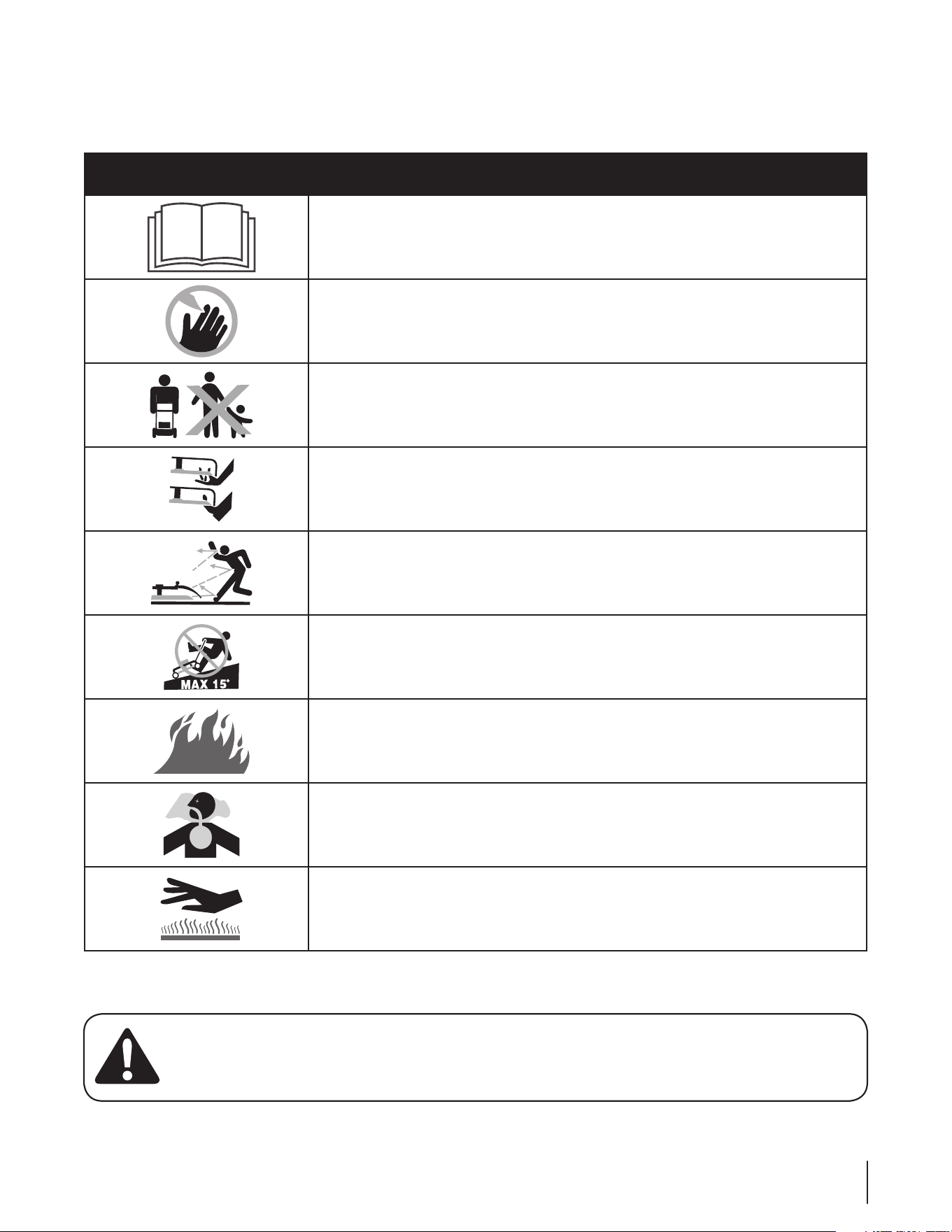
Safety Symbols
This page depicts and describes safety symbols that may appear on this product. Read, understand, and follow all instructions on the
machine before attempting to assemble and operate.
Symbol Description
READ THE OPERATOR’S MANUAL(S)
Read, understand, and follow all instructions in the manual(s) before attempting to
assemble and operate
DANGER — ROTATING BLADES
To reduce the risk of injury, keep hands and feet away. Do not operate unless discharge cover
or grass catcher is in its proper place. If damaged, replace immediately.
DANGER — BYSTANDERS
Do not mow when children or others are around.
DANGER — HAND/ FOOT CUT
Keep hands and feet away from rotating parts.
DANGER — THROWN DEBRIS
Remove objects that can be thrown by the blade in any direction. Wear safety glasses.
DANGER — SLOPES
Use extra caution on slopes. Do not mow slopes greater than 15°.
WARNING—GASOLINE IS FLAMMABLE
Allow the engine to cool at least two minutes before refueling.
WARNING— CARBON MONOXIDE
Never run an engine indoors or in a poorly ventilated area. Engine exhaust contains carbon
monoxide, an odorless and deadly gas.
WARNING— HOT SURFACE
Engine parts, especially the muffler, become extremely hot during operation. Allow engine
and muffler to cool before touching.
8 se c t i O n 2 — iM p O r t a n t sa f e Op e r a t i O n pr a c t i c e s
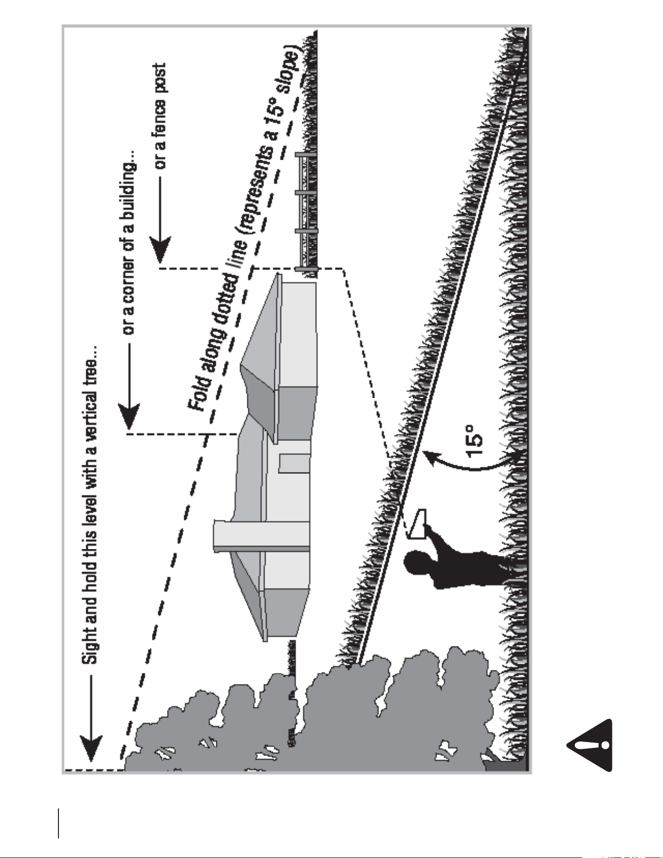
Use this page as a guide to determine slopes where you may not operate safely.
WARNING: Do not operate your machine on such slopes. Do not operate on inclines with a slope in excess of 15 degrees (a
rise of approximately 2-1/2 feet every 10 feet). A riding machine could overturn and cause serious injury. Operate across the
face of slopes, never up and down slopes.

9
Set-Up
3
Initial Adjustments
WARNING! Before performing any adjustments,
disconnect the spark plug wire to prevent the
engine from accidentally starting.
Check the tire pressure. Drive wheels should be inflated to 1.
15 psi. Front wheels (unless foam-filled) should be inflated
to 15 psi.
Note: New tires are overinflated in order to properly seat
the bead to the rim.
The tension of the transaxle drive belt should be adjusted 2.
so that a five pound pull between the engine traction drive
pulley and the pump drive pulley opposite the idler pulley
deflects the belt about 3⁄16”.
The long speed control cables which connect to the pump 3.
control levers should initially be adjusted so that when the
ground speed control levers are in neutral, and the speed
levers are released from the neutral position, the machine
stands still with the engine running.
If the machine starts to creep forward or to the rear in this
situation, then the speed control cable must be adjusted:
Loosen the nut on the cable.a.
Adjust until the drive wheel stops moving.b.
Retighten the nut.c.
Lubricate all fittings listed in the maintenance section.4.
Check that all nuts, bolts, and screws are tight.5.
Gas and Oil Fill-up
WARNING! Use extreme care when handling
gasoline. Gasoline is extremely flammable and the
vapors are explosive. Never fuel machine indoors or
while the engine is hot or running. Extinguish
cigarettes, cigars, pipes, and other sources of ignition.
Note: Your spreader-sprayer is shipped with motor oil in the
engine. However, you MUST check the oil level before operating.
Be careful not to overfill.
Check the engine oil level. Fill to the proper level with 1.
10W30 engine oil rated for service SF or higher.
Move the machine outdoors. Check the engine gasoline 2.
level. When filling the tank, stop when the gasoline
reaches one inch from the top. This space must be left for
expansion. Use fresh, clean, unleaded, regular gasoline.
Controls & Features
4
10
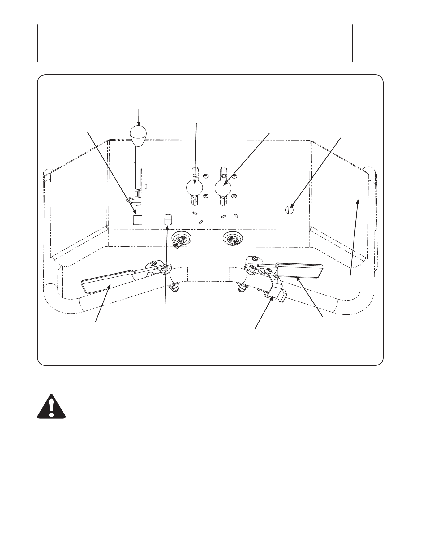
Spreader-sprayer controls and features are illustrated in Fig 4-1 and described on the following pages.
WARNING! Read and follow all safety rules and instructions in this manual, including the entire Operation section,
before attempting to operate this machine. Failure to comply with all safety rules and instructions may result in personal
injury.
Figure 4-1
Spreader Switch
Hopper Shut-Off
Spreader 3rd Hole
Spreader Side
Deflector
Ignition Switch
Forward Ground
Speed Control
Speed Control Lever
(Application-Transport)
Reverse Ground
Speed Control
Sprayer Switch
Right-Hand Nozzle
Valve
11se c t i O n 4 — cO n t r O l s & fe a t u r e s
Ground Speed Control Levers (Forward & Reverse)
Located on the right side of the control panel is the forward
speed control lever. The left lever is for reverse. These two levers
control the maximum output of the hydrostatic transaxle and
thus the ground speed of the spreader independent of the
engine speed. Moving the right lever rearward increases the
forward speed and moving the left lever rearward increases the
reverse speed. These levers moved in unison.
Note: To start the engine both levers must be in their neutral
position.
Speed Control Lever (Application-Transport)
The speed control lever is located on the right side of the control
panel next to the forward ground speed control and is used to
select the level of ground speed. The application speed is the
slower speed and transport is the faster speed.
Hopper Shut-Off
The hopper shut-off is located on the left side of the control
panel and is used to open and close the center and right-hand
holes at the bottom of the spreader hopper.
Ignition Switch
Located on the right side of the control panel, the ignition switch
stops and starts the engine and also shuts off 12 VDC power to
the spreader and sprayer.
Sprayer Switch
The sprayer switch is the right-hand switch located on the
bottom left side of the control panel and is used to turn the
sprayer nozzles on and off.
Spreader Switch
The spreader switch is the left-hand switch located on the
bottom left side of the control panel and is used to turn the
spreader impeller on and off.
Spreader Side Deflector
The spreader side deflector is controlled by the right-hand knob
located on the center of the control panel and is used to stop the
unit from spreading to the right of the spreading path.
Spreader 3rd Hole
The spreader 3rd hole is controlled by the left-hand knob located
on the center of the control panel and is used to close and open
the third (left-hand) hole at the bottom of the spreader hopper,
which prevents or allows the unit to spread on the left side of the
spreading path.
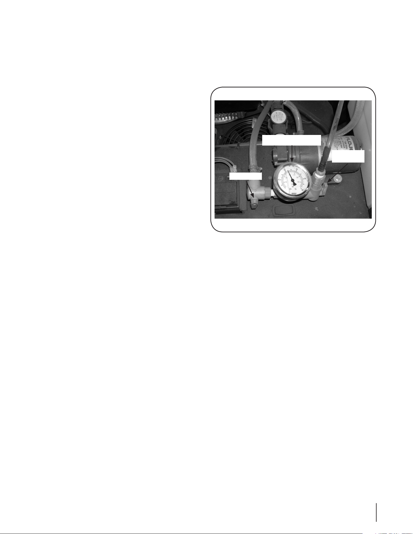
Pressure Gauge
Mounted in the pressure regulator housing next to the battery,
the pressure gauge indicates the pressure in the output lines to
the left, right, and center nozzles and the spray wand. The gauge
is graduated in pounds per square inch (psi) and kilopascals
(kPa). See Fig. 4-2.
Pressure Valves
There are three pressure valves that control the flow of fluids on
the unit:
Main Valve
The main valve is located to the left of the pressure gauge and
controls flow to all three nozzles - left-hand, center, and right-
hand. See Fig. 4-2.
Right Hand Spray Nozzle Valve
The right hand spray nozzle valve is located on the right side of
the control panel. See Fig. 4-1. This valve turns off the flow to the
right hand nozzle to narrow the spray pattern to the center and
left hand side and/or to match that of the spreader when the
chute deflector is used.
Spray Wand Valve
The spray wand valve is located to the right of the pressure
gauge and is used to control flow to the spray wand. See Fig. 4-2.
Pressure Gauge
Main Valve
Spray
Wand Valve
Figure 4-2
12 se c t i O n 4 — cO n t r O l s & fe a t u r e s
Parking Brake
The mechanical disc brake is activated by the lever in the foot
platform area. See Fig. 4-4. Press down on the lever to engage
the park brake, and lift up the lever to release.
Note: The Parking Brake must be engaged to start the engine.
Hour Meter and Tachometer
Located at the upper left edge of the control panel. When the
machine is running the tachometer displays engine rpm. When
the machine is off it displays time of operation.
Fuel Shutoff Valve
Located under the fuel tank, the handle turns 90 degrees to
open or close. When the handle is in a horizontal position, it will
shut off the flow of fuel to the engine. When it is turned to a
vertical position, it will open and allow fuel to flow to the engine.
Anytime the spreader is being transported or, if the machine will
not be in use for 30 minutes or more, close the fuel shutoff valve
to prevent flooding the engine.
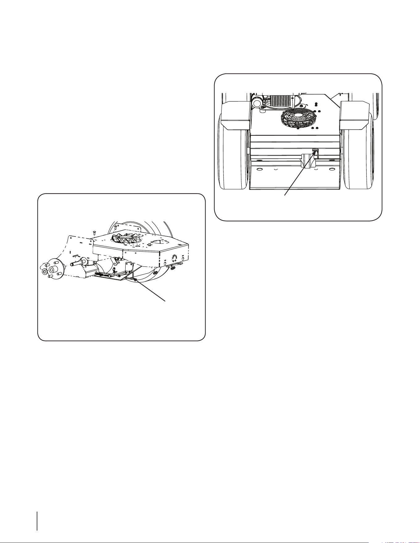
Freewheeling Valve
A valve is located on the side of the hydrostatic transaxle. When
the lever is moved into the “J” slot the spreader-sprayer can be
pushed forward or pulled in reverse without the engine running.
See Fig. 4-3.
Parking Brake
Figure 4-4
Freewheeling
Valve Lever
Figure 4-3

Operation
5
13
Once you have done the above steps, do the following:
Fill the sprayer tank one third full with clean water and then 1.
add 11.6 pints of product to the tank through the strainer
basket while the sprayer is running under full agitation.
After the product is completely mixed, fill the tank to the 2.
proper level with clean water.
Mixing Dry-Bagged Products for Sprayer Use
Pre-mix dry-bagged products with clean water in a five 1.
gallon container to form a slurry.
Fill the sprayer one third with clean water and running 2.
under full agitation.
Slowly pour the slurry into the sprayer through the strainer 3.
basket.
After the product is completely mixed, fill the tank to the 4.
proper level with clean water.
Starting the Sprayer
Check the fuel supply and engine oil level.1.
Check the level of the oil in the pump. It should be halfway 2.
up the sight tube.
Check the pressure in the pump’s pulsation damper. 3.
The pressure should be 10% of the expected operating
pressure.
Clean the in-line strainer if it is dirty.4.
Fill the tank one third full with clean water.5.
Make certain the gate valve in the suction line is open and 6.
the outlet ball valves are closed.
Open the operating lever on the pump’s pressure regulator 7.
so there will be no load on the pump when you start the
engine.
Start the engine.8.
Run the pump at zero pressure for one minute to remove 9.
any air from the system.
Close the operating lever on the pressure regulator and 10.
adjust the pressure to about 100 psi for a flow rate of 1-1/2
to 3 gallons per minute.
Open the ball valve in the hose to the application device. 11.
Check the flow rate out of the application device with a
calibrated container. (See Calibration.)
Adjust the flow rate by adjusting the ball valve in the line to 12.
the agitator or by adjusting the pressure regulator.
When the flow rate is correct, close the ball valve in the 13.
hose to the application device and note the pressure
setting.
You should be able to produce the same flow rate at any
time by returning the pressure to this setting as long as no
change has been made in the hose or application device.
You are now ready to add the product to the tank with the
sprayer running under full agitation.
WARNING: Make certain you thoroughly
understand all of the safety precautions before you
attempt to operate this machine.
IMPORTANT: Your sprayer is shipped with motor oil in the
engine. However, you MUST check the oil level before operating.
Be careful not to overfill. Refer to the Engine Operator’s Manual
included with your unit for complete Gasoline and Oil fill-up
instructions.
Starting the Engine
Connect the spark plug wire.1.
Pump the primer (one time if this is the first start of the 2.
day).
Move the engine throttle lever to the “Choke” position.3.
Pull the recoil handle.4.
Note: Do not crank the engine more than 30 seconds at
one time, because it could damage the starter.
Set the throttle to 50% of full engine RPM and allow the 5.
engine to warm up.
After the engine warms up, set the throttle to 75% of full 6.
engine RPM.
Stopping the Engine
Move the throttle to the “off” position to stop the engine.1.
Disconnect the spark plug wire to prevent unintended 2.
starting.
Using the Sprayer
Adding products to the tank
CAUTION: AVOID ACCIDENTS. FOR SAFETY, READ
THE ENTIRE PRODUCT LABEL INCLUDING
PRECAUTIONARY STATEMENTS. USE ALL PRODUCTS
ONLY AS DIRECTED.
The product label will tell you how much product should be used
per 1000 sq. ft. If the label says you are to use 1.4 ounces per 1000
sq. ft. you divide the number of gallons of water in the tank by
your application rate (gallons per 1000 sq. ft.) and multiply by the
number of ounces of product per 1000 sq. ft. Example is for a 200
gallon sprayer.
200 divided by .0015(application rate) = 133,333.333331.
1.4 divided by 1,000 = .00142.
133,333.33333 times .0014 = 186.6 ounces3.
186.6 divided by 16 = 11.6 pints4.

14 se c t i O n 5 — Op e r a t i O n
After the product is completely mixed, fill the tank to the 14.
proper level with clean water.
Demand Operation
Close the ball valve which stops all flow to the agitator.1.
Push the handle on the directo valve down which permits 2.
flow to the spray wand and turn on the pump switch. This
will force all of the flow from the pump to go to the spray
wand. The pump will operate for a short period to fill the
hose to the spray wand and then will shut off. With the
valves in this position, the pump will turn on when the
spray wand is turned on and will shut off when the spray
wand is turned off.
Note: If you are using a 1.5 GPM spray tip, the pump will
turn on and off as you spray because the pump can output
4.8 GPM.
Note: The pressure gauge should show no more than 45
psi when the spray wand is off. This is controlled by the
pressure switch which is preset at the factory. Pressure
greater than 45 psi will activate an internal circuit breaker
in the pump, stopping it but it will start again in about two
minutes. If this repeats, you will have to adjust the pressure
switch.
To adjust the pressure switch:
Remove the cover from the switch.1.
Adjust the nut holding the small spring on the right side 2.
up for a lower pump turnoff pressure (or down for a higher
pump turnoff pressure). The pump should turn on when
the pressure drops to 25 psi.
Adjust the nut holding the large spring in the center up 3.
for a lower turn-on pressure or down for a higher turn-on
pressure.
Replace the pressure switch cover.4.
After the pressure switch is properly adjusted, check the flow
rate out of the spray wand with a calibrated container. (See
Calibration.) This is the maximum flow rate possible. To reduce
the flow rate, you must adjust the valves so that the pump runs
constantly.
Constant Operation
Open the ball valve which permits flow to the agitator.1.
Push the handle on the directo valve down which permits 2.
flow to the spray wand and turn on the pump switch.
Adjust the pressure regulator until the desired flow rate out 3.
of the spray wand is achieved.
Note: Do not thread the “T” handle of the regulator too far
clockwise or the pump will start to operate intermittently.
For maximum agitation:
Open the ball valve which permits flow to the agitator, and 1.
pull the handle on the directo valve up which shuts off flow
to the spray wand.
Turn the pressure regulator handle counterclockwise 2.
to relieve all of the spring pressure in the regulator and
provide maximum flow to the agitator.
Sprayer Calibration
Hand Spraying
There are two keys to proper calibration of hand spraying. One is
knowing your spraying pace, that is, the time it consistently takes
you to spray an even application of product formulation onto
each 1000 sq. ft. area. The other is always knowing the flow rate
out of the application device of your sprayer.
The first step is to set up your sprayer to spray two gallons per
minute. This is a common flow rate that can be used to check
your spraying pace. To do this, you need a graduated container.
Fill the sprayer tank one third full with clean water and start 1.
it up.
Using the wand or gun that is connected on your sprayer, 2.
spray into the graduated container for one minute. Check
how much water you collected.
Adjust the flow rate by adjusting the ball valve in the line to 3.
the agitator or the pressure regulator if necessary, until you
can collect two gallons in one minute.
The next step is to determine how long it takes you to 4.
evenly spray 1000 sq. ft. Measure an area 20 ft. by 50 ft. on
a paved surface.
Using a stop watch to time your application, spray the area 5.
evenly with clean water. After the water evaporates, spray
the area again and record the time.
Repeat this several times and average the application 6.
times.
Spraying on asphalt or concrete will permit you to see the
pattern you are applying and will give you a better conception
of even application. Check the spray pattern as the water
evaporates to determine if there was even coverage. Spraying
technique is just as important as volume sprayed.
example: If your sprayer is set at a flow rate of two gallons per
minute and your spraying pace is .75 minutes per 1000 sq. ft., you
are applying liquid at a rate of 1.5 gallons per 1000 sq. ft. which is
your application rate. (2 gallons/minute x .75 minutes/1 000 sq. ft.
= 1.5 gallons/ 1 000 sq. ft.) - the application rate.)
It is recommended that the flow rate out of the application
device on your sprayer be checked every working day. It is also
recommended that your spraying pace and the spraying pace
of anyone else who will be using the sprayer be checked every
month or so because, the amount of liquid you apply depends
on the flow rate of your sprayer and your spraying pace. You can
check your spraying pace on every lawn you spray if you have
measured the lawn accurately.
The use of Electronic Digital Flow Meters will permit you to very
accurately measure the flow rate and the total gallons of liquid
sprayed on each lawn. Your tank has fluid level markers which
may also be used to approximate the gallons of liquid that you
spray onto each lawn. This figure should equal your application
rate times the number of 1000 sq. ft. in the lawn.
example: You have sprayed a 10,000 sq. ft. lawn at an
application rate of 1.5 gallons/1000 sq. ft. -- 10 x 1.5 = 15 gallons.
A flow meter should read 15 gallons. When you started there
were 200 gallons of liquid in your tank. Now there should be 185
gallons remaining in the tank.

15se c t i O n 5 — Op e r a t i O n
To decrease the output:• Adjust the pressure regulator to
a lower pressure that still maintains the spray pattern; or
increase the speed of the unit; or change the nozzle tips to
a smaller size.
To increase the output:• Adjust the pressure regulator to
a higher pressure that still maintains the spray pattern; or
decrease the speed of the unit; or change the nozzle tips to
a larger size.
Note: You should always recalibrate after changing the
output.
Tips on Spraying
Use of the Gun
The flow rate is controlled by the nozzle selection, the trigger
position and the sprayer’s pump pressure. The gun’s trigger is
normally held full on and there is a trigger lock to hold it in this
position. However, releasing the trigger slightly will narrow the
pattern when spraying around trees and ornamentals. Each of
the nozzles throws a full cone pattern about five feet in diameter
with a droplet size large enough to help avoid drift yet small
enough for good penetration and thorough coverage.
Determine the application rate in gallons per 1000 sq. ft. •
from the product label.
Divide this figure by your spraying pace in minutes per •
1000 sq. ft. to determine the proper flow rate for the gun in
gallons per minute.
Use this figure to select the proper nozzle and then •
calibrate the sprayer, to spray this flow rate.
To use the gun:
Hold it in your right hand (if you are right handed) with 1.
the hose forming a loop, running under your right arm to
your back, over your left shoulder, down across your chest
and around and out from your right side and back to the
sprayer.
Note: Holding the hose in this way takes the weight of the
hose off of your right arm and allows you to pull the hose
with your whole body and not just your arm. If you are left
handed, the above would be reversed.
Swing the gun with your wrist so that the pattern is in 2.
constant motion and covers a swath about eight feet wide.
Start at the sprayer and work into the lawn. 3.
Walk in parallel paths about eight feet apart and make sure 4.
your spray pattern slightly overlaps the previous pass.
Keep the spray pattern away from ornamentals, trees and 5.
gardens.
Boom Spraying
There are two keys to proper calibration of boom spraying. One
is knowing and controlling the sprayer’s speed over the ground
and the other is knowing the flow rate of the spray tips on the
boom. The following is a simplified procedure:
Measure and mark off a distance of 205 feet in an area that 1.
best represents the average topography for the area to be
sprayed.
Select a safe speed (usually three to six MPH) which can be 2.
maintained while spraying.
Record the engine’s speed (RPM) and the ground speed so 3.
that this speed can be maintained during both calibration
and actual spraying.
With the unit traveling at the selected speed and the 4.
sprayer half full of water, time and record the seconds
taken to travel the 205 feet.
With the sprayer still half full of water, start the sprayer’s 5.
engine and adjust the pump’s pressure regulator to the
desired liquid pressure (normally between 20 and 50 psi).
Collect all the water from one nozzle for the same number 6.
of seconds taken to travel the 205 feet.
example: If it took 35 seconds to travel the 205 feet, collect
the discharge of one nozzle for 35 seconds.
Boom with 20” Nozzle Spacing: The number of fluid ounces •
collected equals the gallons per acre (GPA) output.
Boom with 10” Nozzle Spacing: Two times the number of •
fluid ounces collected equals the gallons per acre (GPA)
output.
Repeat this procedure two more times, collecting water 7.
from a different nozzle each time. Use the average number
of ounces collected from the three nozzles to determine
the gallons per acre output of the boom at the set pressure
and selected RPM and gear setting.
Note: If the ounces collected from any nozzle are 10%
greater or less then the ounces collected from any other
nozzle, it is a sign of wear and all the tips on the boom
should be replaced.
To 8. determine the amount of product to add to the spray
tank, divide the capacity of the tank by the number of
gallons of water per acre (GPA) to determine the area, in
acres, that can be covered with a tankful of spray.
example: 200 Gallon Tank divided by 20 GPA = 10 acres
covered per tankful.
Multiply the application rate of the product per acre times 9.
the acres per tankful and add that amount of product to
the tank through the strainer basket. The tank should be
one third filled with clean water with the sprayer running
under full agitation.
After the product is completely mixed, fill the tank to the 10.
proper level with clean water.
example: 2 quarts per acre x 5 acres per tankful = 10 quarts
or 2.5 gallons of product to be added per tankful of clean
water.

16 se c t i O n 5 — Op e r a t i O n
Use of the Spray Wand
The Spray Wand consists of a ball valve which controls the width
of the pattern, a handle, a trigger valve which turn’s the flow on
and off, an extension, a screen strainer, a hex chamber which
controls the flow to the tip, one of two brass tips and a nut to
hold the tip in place. The low volume tip discharges about 1-1/4
gallons per minute and the high volume tip discharges about
1-1/2 gallons per minute. The tips throw the best pattern at a
pump pressure of about 40 psi. Both tips throw a fan shaped
pattern about eight feet wide with a droplet size large enough to
help avoid drift.
Determine the application rate in gallons per 1000 sq. ft. •
from the product label.
Divide this figure by your spraying pace in minutes per •
1000 sq. ft. to determine the proper flow rate for the wand
in gallons per minute.
Use this figure to select the proper tip and then calibrate •
the sprayer to spray this flow rate.
To use the wand:
Hold it in your right hand (if you are right handed) with 1.
the hose forming a loop, running under your right arm to
your back, over your left shoulder, down across your chest
and around and out from your right side and back to the
sprayer.
Note: Holding the hose in this way takes the weight of the
hose off of your right arm and allows you to pull the hose
with your whole body and not just your arm. If you are left
handed, the above would be reversed.
Hold the wand so that the tip is 18 to 24 inches above the 2.
ground and the spray pattern covers a swath about eight
feet wide.
Hold the wand steady and lock the trigger on. 3.
Start at the sprayer and work into the lawn. 4.
Walk in parallel paths about eight feet apart and make sure 5.
your spray pattern slightly overlaps the previous pass.
Use the ball valve to control the pattern width to keep the 6.
spray pattern away from ornamentals, trees and gardens.
Use of High Pressure Guns
We recommend the 43H GunJets which will operate at pressures
from 200 to 800 psi and are available in brass or aluminum. They
have a trigger handle control and as the trigger is drawn back,
the valve moves from shut off position to initial wide angle cone
spray to continuously narrower cone sprays to a final straight
stream. A knurled nut behind the trigger can be threaded in
or out to stop the trigger at any desired position. There Is also
a trigger lock that can be used to hold the trigger in the “On”
position.
The following spray guns are recommended for spraying small
trees, orchard and nursery spraying and cleaning decks, patios,
brick, aluminum siding, concrete driveways, vehicles and
equipment:
43H-D6 Brass GunJet Spray Gun, 200 to 800 psi1.
43H-AL-D6 Aluminum GunJet Spray Gun, 200 to 800 psi2.
When spraying small trees (up to 30 feet) and shrubs, use a •
spreader-sticker except when applying a dormant oil.
Use a pressure of 200-300 psi and spray only until the •
material starts dripping. No more is necessary. All runoff is
wasted.
Alternate insecticides when spraying during the growing •
season.
Landscape (foliage) area can be measured in square •
footage. Spray volume necessary for coverage is usually
around 10 gallons per 1000 sq. ft. of foliage.

Maintenance & Adjustments
6
17
Maintenance Schedule
Before
Each use
Every
10 Hours
Every
25 Hours
Every
100 Hours
Every
300 Hours
Prior
to Storing
Clean the machine and allow to dry
P P
Check Engine Oil Level
P
Check Air Filter for Dirty, Loose or Damaged Parts
P
Check the fuel level
P
Clean the cooling-air intake
P
Clean Battery Terminals
P P
Clean and Re-oil Air Filter’s Elements
P
Lube Front Axle
P P
Lube Pivot Points
P P
Lube Front Wheel
P P
Check condition and tension of transaxle belt
P
Replace Air Filter Element
P
Change Engine Oil and Replace Oil Filter
P P
Check all nuts, bolts and screws are tight
P P
Replace Spark Plug
P
Change Transaxle Drive Belt
P
Check Spark Plug Condition & Gap
P
Engine Oil: Use 10W30, 10W40 or Shell Rimula 15W40 oil rated SF or higher.
General Purpose Lubrication: Use any NLGI grade 2 multi-purpose grease. Shell Albida EP2 is recommended. Shell Albida EP 2 is a
red-colored multi-purpose grease designed for heavy-duty bearing applications. It has high base oil viscosity for mechanical stability,
has been formulated for high load, low-speed applications, and has excellent lubrication and corrosion protection.

18 se c t i O n 6 — Ma i n t e n a n c e
WARNING! Before performing any maintenance
disconnect the spark plug wire to prevent the
engine from accidentally starting.
General Recommendations
Always observe safety rules when performing any •
maintenance.
The warranty on this machine does not cover items that •
have been subjected to operator abuse or negligence. To
receive full value from warranty, operator must maintain
this machine as instructed here.
Changing of engine-governed speed will void engine •
warranty.
All adjustments should be checked at least once each •
season.
Periodically check all fasteners and make sure these are •
tight.
Close the fuel shutoff valve after each use.•
Engine
Refer to the Kawasaki Owner’s Manual for all engine maintenance
procedures and instructions.
Note: Maintenance, repair, or replacement of the emission
control devices and systems which are being done at owner’s
expense may be performed by any engine repair establishment
or individual. Warranty repairs must be performed by a Cub
Cadet Dealer.
Change the Engine Oil
WARNING! If the engine has been recently run, the
engine, muffler and surrounding metal surfaces will
be hot and can cause burns to the skin. Exercise
caution to avoid burns.
Maintain oil level as instructed in engine manual. The oil filter
should be changed at every oil change interval. Be careful not to
spill oil on any of the belts.
Air Cleaner
Service the pre-cleaner and cartridge/air cleaner element as
instructed in the Kawasaki Owner’s Manual.
Spark Plug
The spark plug should be cleaned and the gap reset once a
season. Refer to the Kawasaki Owner’s Manual for correct plug
type and gap specifications.
Hydrostatic Transmission
The hydrostatic transmission is sealed at the factory and is
maintenance-free. The fluid level cannot be checked and the
fluid cannot be changed. The transaxle is not owner repairable. If
you have a problem with a transaxle, please contact your service
center for a replacement. Do not disassemble the transaxle.
Battery
CALIFORNIA PROPOSITION 65 WARNING!
Battery posts, terminals, and related accessories
contain lead and lead compounds, chemicals known
to the State of California to cause cancer and
reproductive harm. Wash hands after handling.
This machine is equipped with a belt-driven 20 AMP capacity
generator (dynamo) with a solid state voltage regulator. The
regulator will maintain the system voltage above 13 VDC when
the engine is running, regardless of whether the spreader and/
or sprayer are being operated. The battery is a sealed 12 VDC - 18
AMP-hour rated lead-acid type and is maintenance-free. Acid
levels cannot be checked and fluid can not be added.
Always keep the battery cables and terminals clean and •
free of corrosive build-up.
After cleaning the battery and terminals, apply a light coat •
of petroleum jelly or grease to both terminals.
CAUTION: If removing the battery for cleaning,
disconnect the NEGATIVE (Black) wire from it’s
terminal first, followed by the POSITIVE (Red) wire.
When re-installing the battery, always connect the
POSITIVE (Red) wire its terminal first, followed by the
NEGATIVE (Black) wire. Be certain that the wires are
connected to the correct terminals; reversing them
could result in serious damage to your engine’s
alternating system.
Cleaning the Unit
Clean underside of the machine before each use to prevent
build-up of fertilizer or other debris. Any fuel or oil spilled on
the machine should be wiped off promptly. Do NOT allow
debris to accumulate around the cooling fins of the engine, the
transmission’s cooling fan or on any other part of the machine,
especially the belts and pulleys. Wash the machine off with
water. Be sure to clean out materials from under the hopper.
Allow the machine to dry before storing. Follow steps below for
this job.
Disconnect the spark plug wire.1.
Close the fuel shutoff valve.2.
Allow the machine to cool.3.
Tip the machine on the side with the air cleaner facing up. 4.
Hold the machine firmly.
WARNING: Never tip the machine more than 90º in
any direction and do not leave the machine tipped
for any length of time. Oil can drain into the upper
part of the engine causing a starting problem.
Wash the machine off with water. Be sure to clean out 5.
materials from under the hopper.
IMPoRtANt: Do not use a pressure washer to clean your
unit. These may cause damage to bearings, or the engine.
Put the machine back on its wheels on the ground. 6.
19se c t i O n 6 — Ma i n t e n a n c e
Changing the Pump Drive Belt
At the top of the engine base, remove the guard covering 1.
the transmission fan/pulley.
Access engine drive pulley, idler pulley and belt from the 2.
left hand side of the unit. See Fig. 6-3.
Release the drive belt idler tension by disconnecting the 3.
idler arm tension spring where it is attached to the engine
base frame. See Fig. 6-3.
Remove the old belt and mount a new belt onto the 4.
transmission drive pulley and the engine drive pulley.
Install the belt onto the alternator drive pulley, if equipped.
See Fig. 6-3.
Position the idler pulley on the outer edge of the drive belt.5.
Reconnect the tension spring to the engine base frame.6.
Reinstall the guard covering the transmission fan/pulley.7.
Off-Season Storage
The following steps should be taken to prepare your unit for
storage.
Clean and lubricate the unit thoroughly as described in the •
lubrication instructions.
Do not use a pressure washer to clean your unit.•
Place the machine in locked storage to avoid tampering or •
use by an untrained operator.
Store the unit in a dry, clean area. Do not store next to •
corrosive materials, such as fertilizer.
If the machine is to be in storage for more than 30 days, drain the
fuel tank, run the engine to drain the carburetor dry, change the
oil, remove the spark plug and pour a teaspoonful of oil into the
cylinder. Pull the starter to crank the engine and distribute the oil
then replace the spark plug.
When storing any type of power equipment in a poorly
ventilated or metal storage shed, care should be taken to
rust-proof the equipment. Using a light oil or silicone, coat
the equipment, especially cables and all moving parts of your
machine before storage.
Lubrication
WARNING! Before lubricating, repairing, or
inspecting, always set parking brake, stop engine
and remove key to prevent unintended starting.
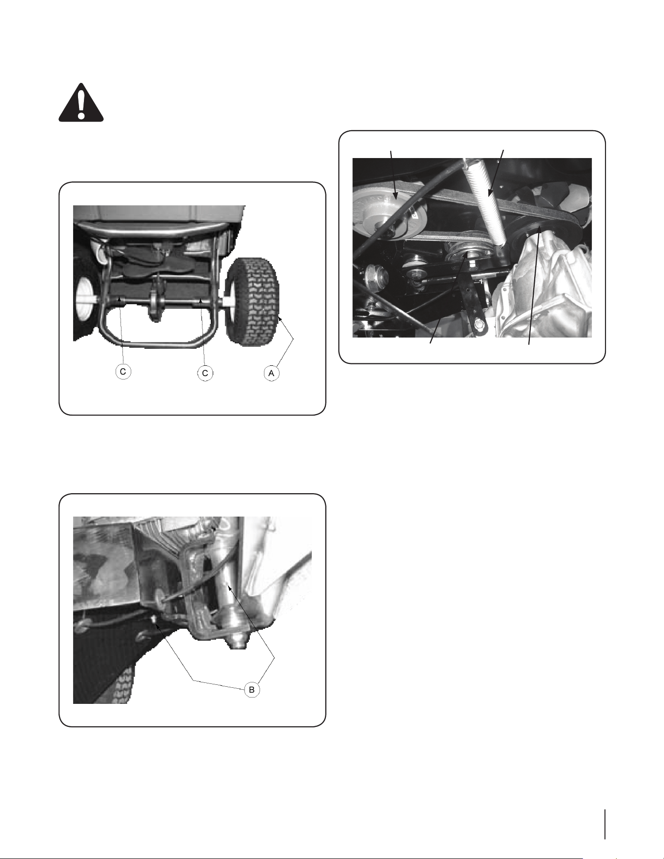
Front Wheel/Axle Bearings
The front wheel bearings (A) and the front axle bearings (C) is
equipped with grease fittings. See Fig. 6-1.
Pivot Points
Lubricate the two grease fittings (B) on the pivot assembly. See
Figure 6-2.
Idler Pulley
Idler Tension Spring
Transmission Drive Pulley
Engine Drive Pulley
Figure 6-1
Figure 6-3
Figure 6-2

Troubleshooting
7
20
Problem Cause Remedy
Engine Fails to start Spark plug boot disconnected.1.
Fuel tank empty or stale fuel.2.
Engine not primed (if equipped with primer). 3.
Faulty spark plug.4.
Blocked fuel line.5.
Engine flooded. 6.
Fuel valve (if equipped) closed.7.
Engine not choked (if equipped with choke).8.
Connect wire to spark boot.1.
Fill tank with clean, fresh gasoline.2.
Prime engine as instructed in the Operation 3.
section.
Clean, adjust gap, or replace.4.
Clean fuel line.5.
Wait a few minutes to restart, but do not 6.
prime.
Open fuel valve. See engine manual.7.
Choke engine. See engine manual.8.
Engine runs erratic Spark plug boot loose.1.
Blocked fuel line or stale fuel. 2.
Vent in gas cap plugged.3.
Water or dirt in fuel system.4.
Dirty air cleaner.5.
Unit running with CHOKE (if equipped) 6.
applied.
Connect and tighten spark plug boot.1.
Clean fuel line; fill tank with clean, fresh 2.
gasoline.
Clear vent.3.
Drain fuel tank. Refill with fresh fuel.4.
Refer to engine manual.5.
Move throttle lever to CHOKE OFF.6.
Engine overheats Engine oil level low.1.
Air flow restricted.2.
Fill crankcase with proper oil.1.
Clean area around and on top of engine.2.
Occasional skips
(hesitates) at
high speed
Spark plug gap too close.1. Adjust gap to .030”.1.
Idles poorly Spark plug fouled, faulty, or gap too wide.1.
Dirty air cleaner.2.
Reset gap to .030” or replace spark plug.1.
Refer to engine manual.2.

Specifications
8
21
Note: Specifications subject to change without notice.
* As rated by engine manufacturer.
Specifications:
Model: 125 lb Spreader & 10 gallon Sprayer
Engine Mfg: Kawasaki
HP: 6.5*
Type: 4 Cycle Single Cylinder
Starter: Electric (Recoil Back-Up)
Air Cleaner: Dual Element Dry
Lube: Pressurized
Fuel Capacity: 2 Quarts
Charging System: 20 Amp Generator & Voltage Reg.
Battery: 12 VDC, 18 Amp-hour, Sealed
Traction Drive: Hydro Gear, Model 510 Hydrostat
Hydraulic Oil Capacity: 0.7 Quarts
Hydraulic Filtration: Internal
Ground Speed: 0 to 5 mph
Wheels: 18 x 8.50-8 rear, 13 x 7.50 front
Width: 37. 2 5”
Height: 47”
Length: 60”
Weight: 445 lbs. empty

CALIFORNIA EMISSION CONTROL WARRANTY STATEMENT
YOUR WARRANTY RIGHTS AND OBLIGATIONS
The California Air Resources Board and MTD Consumer Group Inc are pleased to explain the evaporative emission control system warranty on your 2008 lawn
mower. In California, new lawn mowers must be designed, built and equipped to meet the State’s stringent anti-smog standards. MTD Consumer Group Inc must
warrant the EECS on your lawn mower for the period of time listed below provided there has been no abuse, neglect or improper maintenance of your lawn mower.
Your EECS may include parts such as the carburetor, fuel-injection system, the ignition system, catalytic converter, fuel tanks, fuel lines, fuel caps, valves,
canisters, filters, vapor hoses, clamps, connectors, and other associated emission-related components.
Where a warrantable condition exists, MTD Consumer Group Inc will repair your lawn mower at no cost to you including diagnosis, parts and labor.
MANUFACTURER’S WARRANTY COVERAGE:
This evaporative emission control system is warranted for two years. If any evaporative emission-related part on your equipment is defective, the part will be
repaired or replaced by MTD Consumer Group Inc.
OWNER’S WARRANTY RESPONSIBILITIES:
As the lawn mower owner, you are responsible for performance of the required maintenance listed in your owner’s manual. MTD Consumer Group Inc recommends
that you retain all receipts covering maintenance on your lawn mower, but MTD Consumer Group Inc cannot deny warranty solely for the lack of receipts.
As the lawn mower owner, you should however be aware that MTD Consumer Group Inc may deny you warranty coverage if your lawn mower or a part has failed
due to abuse, neglect, or improper maintenance or unapproved modifications.
You are responsible for presenting your lawn mower to MTD Consumer Group Inc’s distribution center or service center as soon as the problem exists. The
warranty repairs should be completed in a reasonable amount of time, not to exceed 30 days. If you have a question regarding your warranty coverage, you should
contact the MTD Consumer Group Inc Service Department at 1-800-800-7310.
GENERAL EMISSIONS WARRANTY COVERAGE:
MTD Consumer Group Inc warrants to the ultimate purchaser and each subsequent purchaser that the lawn mower is: Designed, built and equipped so as to
conform with all applicable regulations; and free from defects in materials and workmanship that cause the failure of a warranted part to be identical in all material
respects to that part as described in MTD Consumer Group Inc’s application for certification.
The warranty period begins on the date the lawn mower is delivered to an ultimate purchaser or first placed into service. The warranty period is two years.
Subject to certain conditions and exclusions as stated below, the warranty on emission-related parts is as follows:
1. Any warranted part that is not scheduled for replacement as required maintenance in the written instructions supplied, is warranted for the warranty period
stated above. If the part fails during the period of warranty coverage, the part will be repaired or replaced by MTD Consumer Group Inc according to subsection
(4) below. Any such part repaired or replaced under warranty will be warranted for the remainder of the period.
2. Any warranted part that is scheduled only for regular inspection in the written instructions supplied is warranted for the warranty period stated above. Any such
part repaired or replaced under warranty will be warranted for the remaining warranty period.
3. Any warranted part that is scheduled for replacement as required maintenance in the written instructions supplied is warranted for the period of time before the
first scheduled replacement date for that part. If the part fails before the first scheduled replacement, the part will be repaired or replaced by MTD Consumer
Group Inc according to subsection (4) below. Any such part repaired or replaced under warranty will be warranted for the remainder of the period prior to the
first scheduled replacement point for the part.
4. Repair or replacement of any warranted part under the warranty provisions herein must be performed at a warranty station at no charge to the owner.
5. Notwithstanding the provisions herein, warranty services or repairs will be provided at all of our distribution centers that are franchised to service the subject
engines or equipment.
6. The lawn mower owner will not be charged for diagnostic labor that is directly associated with diagnosis of a defective, emission-related warranted part,
provided that such diagnostic work is performed at a warranty station.
7. MTD Consumer Group Inc is liable for damages to other engine or equipment components proximately caused by a failure under warranty of any warranted
part.
8. Throughout the lawn mower warranty period stated above, MTD Consumer Group Inc will maintain a supply of warranted parts sufficient to meet the expected
demand for such parts.
9. Any replacement part may be used in the performance of any warranty maintenance or repairs and must be provided without charge to the owner. Such use will
not reduce the warranty obligations of MTD Consumer Group Inc.
10. Add-on or modified parts that are not exempted by the Air Resources Board may not be used. The use of any non-exempted add-on or modified parts by the
ultimate purchaser will be grounds for disallowing a warranty claims. MTD Consumer Group Inc will not be liable to warrant failures of warranted parts caused
by the use of a non-exempted add-on or modified part.

WARRANTED PARTS:
The repair or replacement of any warranted part otherwise eligible for warranty coverage may be excluded from such warranty coverage if MTD Consumer Group
Inc demonstrates that the lawn mower has been abused, neglected, or improperly maintained, and that such abuse, neglect, or improper maintenance was the
direct cause of the need for repair or replacement of the part. That notwithstanding, any adjustment of a component that has a factory installed, and properly
operating, adjustment limiting device is still eligible for warranty coverage. The following emission warranty parts are covered:
(1) Fuel Metering System
•Coldstartenrichmentsystem(softchoke)
•Carburetorandinternalparts
•Fuelpump
•Fueltank
(2) Air Induction System
•Aircleaner
•Intakemanifold
(3) Ignition System
•Sparkplug(s)
•Magnetoignitionsystem
(4) Exhaust System
•Catalyticconverter
•SAI(Reedvalve)
(5) Miscellaneous Items Used in Above System
•Vacuum,temperature,position,timesensitivevalvesandswitches
•Connectorsandassemblies
(6) Evaporative Control
•FuelhosecertifiedforARBevaporativeemissions2008
•Fuelhoseclamps
•Tetheredfuelcap
•Carboncanister
•Vaporlines
GDOC-100175 Rev. C

CUB CADET LLC
MANUFACTURER’S LIMITED WARRANTY
FOR COMMERCIAL LAWN APPLICATION EQUIPMENT
Cub Cadet LLC, P.O. BOX 361131 CLEVELAND, OHIO 44136-0019, Phone: 1-877-282-8684
MTD Products Limited, Kitchener, ON N2G 4J1, Phone: 1-800-668-1238
GDOC-100208 REV. A
IMPORTANT: To obtain warranty coverage owner must present an
original proof of purchase and applicable maintenance records to the
servicing dealer. Please see the operator’s manual for information on
required maintenance and service intervals.
The limited warranty set forth below is given by Cub Cadet LLC with
respect to new merchandise purchased or leased and used in the
United States and/or its territories and possessions, and by MTD
Products Limited with respect to new merchandise purchased or
leased and used in Canada and/or its territories and possessions
(either entity respectively, “Cub Cadet”).
Cub Cadet warrants this product (excluding its Normal Wear Parts,
Batteries and Attachments as described below) against defects in
material and workmanship for a period of one (1) year commencing
on the date of original retail purchase or lease and will, at its option,
repair or replace, free of charge, any part found to be defective in
materials or workmanship.
Normal Wear Parts are warranted to be free from defects in material
and workmanship for a period of thirty (30) days or one hundred
(100) operation hours, whichever comes first, commencing on the
date of original retail purchase or lease. Normal wear parts include,
but are not limited to items such as: belts, blades, blade adapters,
grass bags, rider deck wheels, seats, and tires.
Batteries have a one-year prorated limited warranty against defects
in material and workmanship, with 100% replacement during the
first three months. After three months, the battery replacement
credit is based on the months remaining in the twelve (12) month
period dating back to the original date of original sale or lease. Any
replacement battery will be warranted only for the remainder of the
original warranty period.
Attachments — Cub Cadet warrants attachments for this product
against defects in material and workmanship for a period of one (1)
year, commencing on the date of the attachment’s original purchase
or lease. Attachments include, but are not limited to items such as:
grass collectors and mulch kits.
This limited warranty shall only apply if this product has been
operated and maintained in accordance with the Operator’s Manual
furnished with the product, and has not been subject to misuse,
abuse, neglect, accident, improper maintenance, alteration,
vandalism, theft, fire, water, or damage because of other peril or
natural disaster. Damage resulting from the installation or use of any
part, accessory or attachment not approved by Cub Cadet for use
with the product(s) covered by this manual will void your warranty as
to any resulting damage. In addition, Cub Cadet may deny warranty
coverage if the hour meter, or any part thereof, is altered, modified,
disconnected or otherwise tampered with.
HOW TO OBTAIN SERVICE: Warranty service is available, WITH
PROOF OF PURCHASE AND APPLICABLE MAINTENANCE RECORDS,
through your local authorized service dealer. To locate the dealer in
your area:
In the U.S.A.:
Check your Yellow Pages, or contact Cub Cadet LLC at P.O. Box
361131, Cleveland, Ohio 44136-0019, call 1-877-282- 8684
or log on to our website at www.cubcadet.com.
In Canada:
Contact MTD Products Limited, Kitchener, ON N2G 4J1, call 1-800-
668-1238 or log on to our website at www.mtdcanada.com.
Without limiting the foregoing, this limited warranty does not provide
coverage in the following cases:
a. Routine maintenance items such as lubricants, filters, blade
sharpening, tune-ups, brake adjustments, clutch adjustments,
deck adjustments, and normal deterioration of the exterior finish
due to use or exposure.
b. Service completed by someone other than an authorized service
dealer.
c. Cub Cadet does not extend any warranty for products sold or
exported outside of the United States and/or Canada, and their
respective possessions and territories, except those sold through
Cub Cadet’s authorized channels of export distribution.
d. Replacement parts and\or accessories that are not genuine Cub
Cadet parts.
e. Transportation charges and service calls.
There are no implied warranties, including without limitation any
implied warranty of merchantability or fitness for a particular
purpose. No warranties shall apply after the applicable period
of express written warranty above. No other express warranties
beyond those mentioned above, given by any person or entity,
including a dealer or retailer, with respect to any product, shall
bind Cub Cadet. The exclusive remedy is repair or replacement of
the product as set forth above. The terms of this warranty provide
the sole and exclusive remedy arising from the sale and/or lease
of the products covered hereby. Cub Cadet shall not be liable for
any incidental or consequential loss or damage including, without
limitation, expenses incurred for substitute or replacement lawn
care services or for rental expenses to temporarily replace a
warranted product.
Some jurisdictions do not allow the exclusion or limitation of
incidental or consequential damages, or limitations on how long an
implied warranty lasts, so the above exclusions or limitations may not
apply to you.
In no event shall recovery of any kind be greater than the amount of
the purchase price of the product sold. Alteration of safety features of
the product shall void this warranty. You assume the risk and liability
for loss, damage, or injury to you and your property and/or to others
and their property arising out of the misuse or inability to use the
product.
This limited warranty shall not extend to anyone other than the
original purchaser or to the person for whom it was purchased as a
gift.
HOW LOCAL LAWS RELATE TO THIS WARRANTY: This limited
warranty gives you specific legal rights, and you may also have other
rights that vary in different jurisdictions.

