– 1 –
English
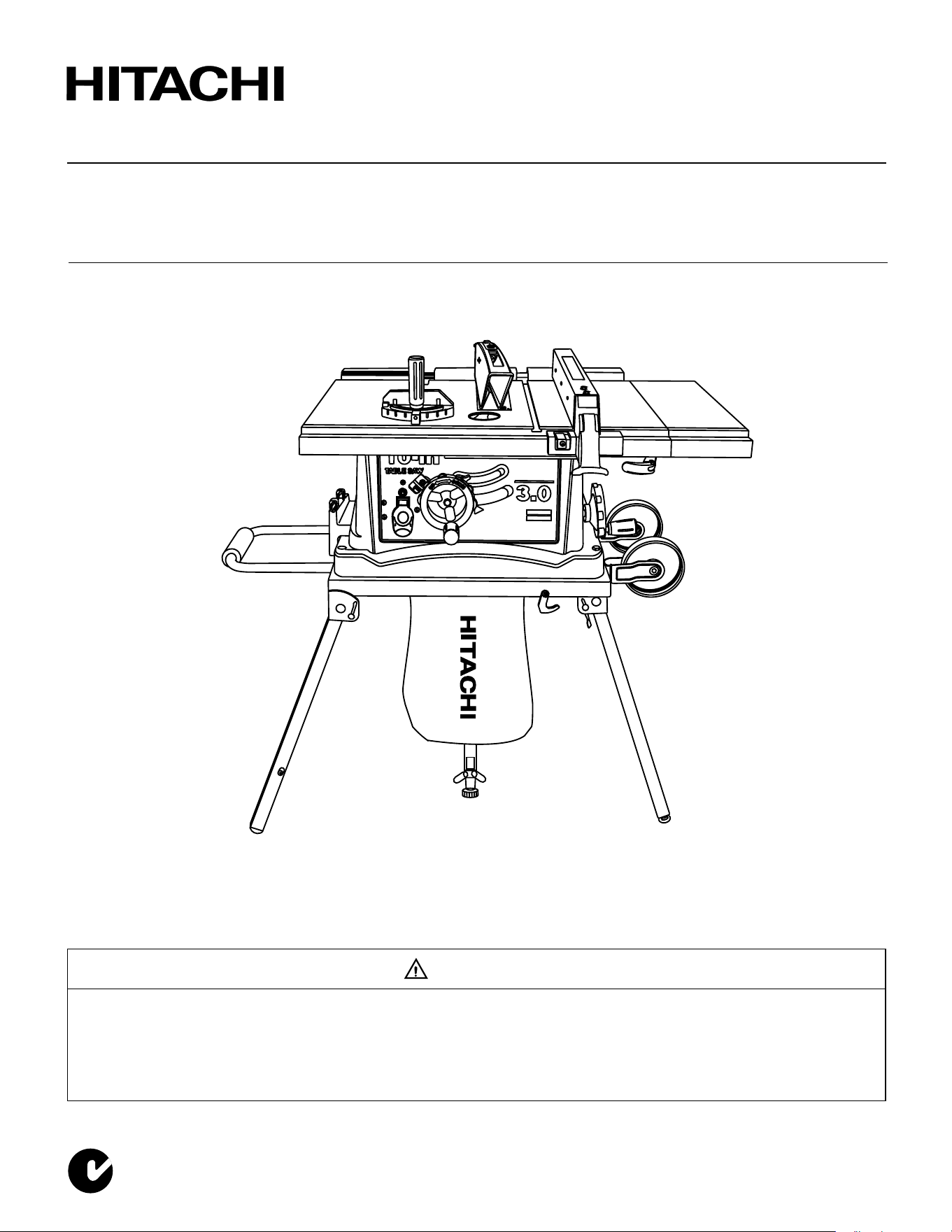
Model Jobsite Table Saw
C 10FR
INSTRUCTION MANUAL AND SAFETY INSTRUCTIONS
Improper and unsafe use of this power tool can result in death or serious bodily injury!
This manual contains important information about product safety. Please read and understand this manual
before operating the power tool. Please keep this manual available for others before they use the power
tool.
WARNING
Hitachi Koki
N136
OFF
ON

– 2 –
English
CONTENTS
SECTION PAGE
Product Specifications ................................................................................................................ 3
Power Tool Safety ...................................................................................................................... 4
Table Saw Safety ........................................................................................................................ 5
Electrical Requirements and Safety ........................................................................................... 6
Accessories and Attachments .................................................................................................... 7
Tools Needed for Assembly ....................................................................................................... 7
Carton Contents ......................................................................................................................... 7
Know Your Table Saw ................................................................................................................ 9
Assembly and Adjustments ........................................................................................................ 10
Operation .................................................................................................................................... 17
Maintenance ............................................................................................................................... 21
Troubleshooting Guide ............................................................................................................... 22
Push Stick Pattern ...................................................................................................................... 23
Parts List ..................................................................................................................................... 24
English
– 3 –
English
WARNING
Some dust created by power sanding, sawing, grinding, drilling and other construction activities contains
chemicals known to the state of California to cause cancer, birth defects or other reproductive harm. Some
examples of these chemicals are:
• Lead based paints
• Crystalline silica from bricks, cement and other masonry products
• Arsenic and chromium from chemically treated lumber
Your risk from these exposures varies, depending on how often you do this type of work. To reduce your
exposure to these chemicals, work in a well-ventilated area and work with approved safety equipment, such as
dust masks that are specially designed to filter out microscopic particles.
PRODUCT SPECIFICATIONS
MOTOR SAW
Type ............................................... Universal Table Size with Extension........................
31-25/32” x 19-21/64”
Amps .............................................. 6.5A (807mm x 491mm)
Voltage ...........................................
230-240V/50Hz
Table Extension ...................................... Right, Rear
Watts .............................................. 1430W
Extension Fence Capacity (Maximum).... 24” (610mm) Right
No load speed ................................ 5,000/min
Blade Size................................................ 10” (255mm)
Overload Protection ....................... YES
Rip Scale ................................................. YES
Rip Fence ................................................ YES
Miter Gauge ............................................ YES
Maximum Cut Depth @ 90º ....................
3-1/8” (80mm)
Maximum Cut Depth @ 45º .................... 2-1/2” (64mm)
Net Weight ..............................................
73 lbs (33.3kg)
WARNING
To avoid electrical hazards, fire hazards or damage to the table saw, use proper circuit protection.
This table saw is wired at the factory for 230-240 Volt operation. It must be connected to a 230-240 Volt / 6.5
Ampere time delay fuse or circuit breaker. To avoid shock or fire, replace power cord immediately if it is worn,
cut or damaged in any way. Before using your table saw, it is critical that you read and understand these safety
rules. Failure to follow these rules could result in serious injury to you or damage to the table saw.
WARNING
Through poor conditions of the electrical MAINS, shortly voltage drops can appear when starting the
EQUIPMENT. This can influence other equipment (e.g. blinking of a lamp). If the MAINS-IMPEDANCE Zmax <
0.33 OHM, such disturbances are not expected. (In case of need, you may contact your local supply authority
for further information).

– 4 –
English
POWER TOOL SAFETY
WARNING
Before using your table saw, it is critical that you read and understand these safety rules. Failure to follow
these rules could result in serious injury or damage to the table saw.
Good safety practices are a combination of common
sense, staying alert and understanding how to use your
power tool. To avoid mistakes that could cause serious
injury, do not plug in your power tool until you have read
and understood the following safety rules:
1. READ and become familiar with this entire
Operator’s Manual. LEARN the tool’s applications,
limitations and possible hazards.
2.
Look for this symbol that identifies important
safety precautions. It means BE ALERT! YOUR
SAFETY IS INVOLVED!
3. NEVER OPERATE THIS MACHINE WITHOUT THE
SAFETY GUARD IN PLACE FOR ALL THROUGH
–SAWING OPERATIONS.
4. DO NOT USE IN A DANGEROUS ENVIRONMENT
such as damp or wet locations or in the rain. Keep
work area well lighted.
5. DO NOT use power tools in the presence of
flammable liquids or gases.
6. KEEP WORK AREA CLEAN. Cluttered areas and
benches invite accidents.
7. KEEP CHILDREN AWAY. All visitors should be kept
at a safe distance from the work area.
8. DO NOT FORCE THE TOOL. It will do the job
better and safer if used at the rate for which it was
designed.
9. USE THE RIGHT TOOL. Don’t force the tool or
attachment to do a job for which it is not designed.
10. WEAR PROPER APPAREL. DO NOT wear loose
clothing, gloves, neckties, rings, bracelets or other
jewelry that may get caught in moving parts.
Non-slip footwear is recommended. Wear protective
hair covering to contain long hair.
11. WEAR A FACE MASK OR DUST MASK. Sawing,
cutting and sanding operations produce dust.
12. DISCONNECT TOOLS before servicing and when
changing accessories, such as blades, cutters, etc.
13. REDUCE THE RISK OF UNINTENTIONAL
STARTING. Make sure the switch is in the OFF
position before plugging tool into the power supply.
14. USE ONLY RECOMMENDED ACCESSORIES.
Consult the Operator’s Manual for recommended
accessories. The use of improper accessories may
cause injury to you or damage to the tool.
15. REMOVE ADJUSTING KEYS AND WRENCHES.
Form the habit of checking to see that keys and
adjusting wrenches are removed from the tool
before turning ON.
16. NEVER LEAVE TOOL RUNNING UNATTENDED.
TURN THE POWER OFF. Do not leave the tool
before the blade comes to a complete stop.
17. NEVER STAND ON TOOL. Serious injury could
occur if the tool is tipped or if the cutting tool is
unintentionally contacted.
18. DO NOT OVERREACH. Keep proper footing and
balance at all times.
19. MAINTAIN TOOLS WITH CARE. Keep tools sharp
and clean for most efficient and safest performance.
Follow instructions for lubricating and changing
accessories.
20. CHECK FOR DAMAGED OR LOOSE PARTS.
Check for alignment of moving parts, binding
of moving parts, loose mounting and any other
conditions that may affect its safe operation. A guard
or other part that is loose or damaged should be
properly adjusted, repaired or replaced.
21. MAKE WORKSHOP CHILDPROOF with padlocks,
master switches or by removing starter keys.
22. DO NOT operate the tool if you are under the
influence of any drugs, alcohol or medication that
could impair your ability to use the tool safely.
23. USE A DUST COLLECTION SYSTEM whenever
possible. Dust generated from certain materials can
be hazardous to your health and, in some cases,
a fire hazard. Always operate the power tool in a
well-ventilated area with adequate dust removal.
24. ALWAYS WEAR EYE PROTECTION. Any power
tool can throw debris into your eyes that could
cause permanent eye damage. ALWAYS wear
safety goggles (not glasses) that comply with ANSI
safety standard Z87.1. Everyday glasses have only
impact resistant lenses. They ARE NOT safety
glasses.
NOTE: Glasses or goggles not in compliance with
ANSI Z87.1 could cause serious injury when they
break.
25. DIRECTION OF FEED. Feed work into a blade or
cutter against the direction of rotation of the blade or
cutter only.
WARNING

– 5 –
English
TABLE SAW SAFETY
1. ALWAYS USE SAW BLADE GUARD, splitter
and antikickback pawls for every operation for
which they can be used, including through sawing.
Through sawing operations are those in which the
blade cuts completely through the workpiece when
ripping or crosscutting.
2. ALWAYS HOLD WORK FIRMLY against the miter
gauge or rip fence.
3. ALWAYS USE a push stick, especially when ripping
narrow stock. Refer to ripping instructions in this
Operator’s Manual where the push stick is covered
in detail. A pattern for making your own push stick is
included on page 23.
4. NEVER PERFORM ANY OPERATION FREEHAND,
which means using only your hands to support
or guide the workpiece. Always use either the
fence or the miter gauge to position and guide
the work.
WARNING: FREEHAND CUTTING IS THE MAJOR
CAUSE OF KICKBACK AND FINGER/HAND
AMPUTATIONS.
5. NEVER STAND or have any part of your body in
line with the path of the saw blade. Keep your hands
out of the saw blade path.
6. NEVER REACH behind or over the cutting tool for
any reason.
7. REMOVE the rip fence when crosscutting.
8. DO NOT USE a molding head with this saw.
9. FEED WORK INTO THE BLADE against the
direction of rotation only.
10. NEVER use the rip fence as a cut-off gauge when
crosscutting.
11. NEVER ATTEMPT TO FREE A STALLED SAW
BLADE without first turning the saw OFF. Turn
power switch OFF immediately to prevent motor
damage.
12. PROVIDE ADEQUATE SUPPORT to the rear
and the sides of the saw table for long or wide
workpieces.
13. AVOID KICKBACKS (work thrown back towards
you) by keeping the blade sharp, the rip fence
parallel to the saw blade and by keeping the splitter,
anti-kickback pawls and guards in place, aligned
and functioning. Do not release work before passing
it completely beyond the saw blade. Do not rip work
that is twisted, warped or does not have a straight
edge to guide it along the fence.
14. AVOID AWKWARD OPERATIONS and hand
positions where a sudden slip could cause your
hand to move into the saw blade.
15. NEVER USE SOLVENTS to clean plastic parts.
Solvents could possibly dissolve or otherwise
damage the material. Only a soft damp cloth should
be used to clean plastic parts.
16. MOUNT your table saw on a bench or stand
before performing any cutting operations. Refer to
ASSEMBLY AND ADJUSTMENTS on page 10.
17. NEVER CUT METALS or materials that may make
hazardous dust.
18. ALWAYS USE IN A WELL-VENTILATED AREA.
Remove sawdust frequently. Clean out sawdust
from the interior of the saw to prevent a potential
fire hazard. Attach a vacuum to the dust port for
additional sawdust removal.
19. NEVER LEAVE THE SAW RUNNING
UNATTENDED. Do not leave the saw until the blade
comes to a complete stop.
20. For proper operation follow the instructions in this
Operator’s Manual entitled ASSEMBLY AND
ADJUSTMENTS (Page 10). Failure to provide
sawdust fall-through and removal hole will allow
sawdust to build up in the motor area resulting in a
fire hazard and potential motor damage.

– 6 –
English
ELECTRICAL REQUIREMENTS AND SAFETY
CONNECTING TO THE POWER SUPPLY
Check that the power supply and plug used is in accordance with your drill press. Have a look at the rating plate of the
motor or the rating on the drill press. Any changes should always be carried out by a qualified electrician.
This machine must be earthed.
If not properly earthed this machine can cause an electrical shock. Be sure that the power supply outlet is earthed. If
there is any doubt, have it checked by a qualified electrician.
Avoid contact with the terminals on the plug when installing (removing) the plug to (from) the power supply
outlet. Contact will cause a severe electrical shock.
USING AN EXTENSION LEAD
The use of any extension lead will cause some loss of power. To keep this to a minimum and to prevent overheating
and motor burn-out, ask advice from a qualified electrician to determine the minimum wire size of the extension lead.
The extension lead should be equipped with an earthed type plug that fits the power supply outlet at one end, and with
an earthed type socket that fits the plug of this machine at the other end.
WARNING
WARNING
– 7 –
English
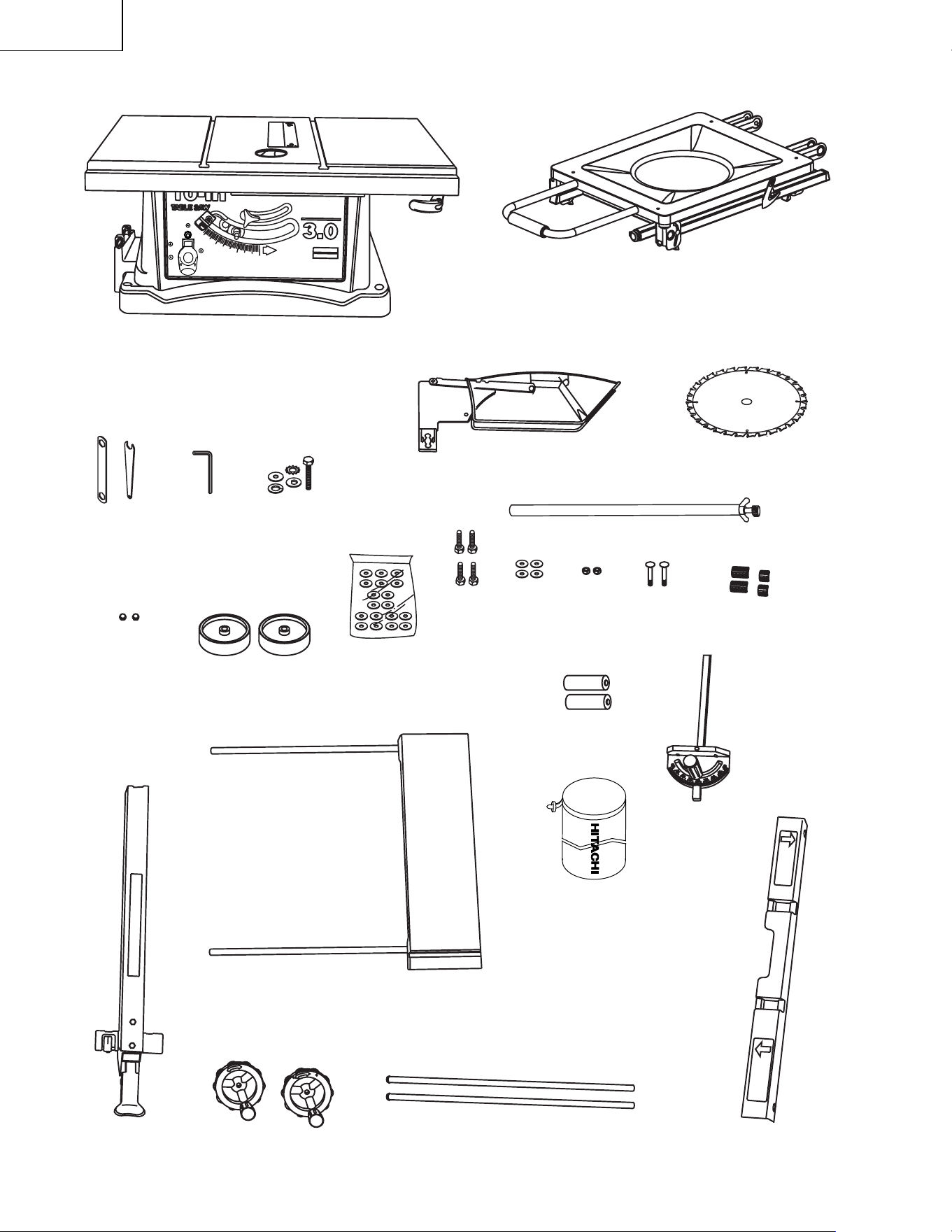
UNPACKING AND CHECKING CONTENTS
Separate all parts from packing materials. Check each
part with the illustration on the next page and the “Table
of Loose Parts” to make certain all items are accounted
for, before discarding any packing material.
TABLE OF LOOSE PARTS
ACCESSORIES AND ATTACHMENTS
RECOMMENDED ACCESSORIES
Visit your Hardware Department or see the Power
and Hand Tools Catalog to purchase recommended
accessories for this power tool.
WARNING
To avoid the risk of personal injury:
• Do not use a dado with a diameter larger than 6”
(152.4mm).
• Maximum dado width is 1/2” (12.7mm). DO NOT
USE WIDER COMBINATIONS.
• Do not use molding head set with this saw.
• Do not modify this power tool or use accessories
not recommended by Store.
WARNING
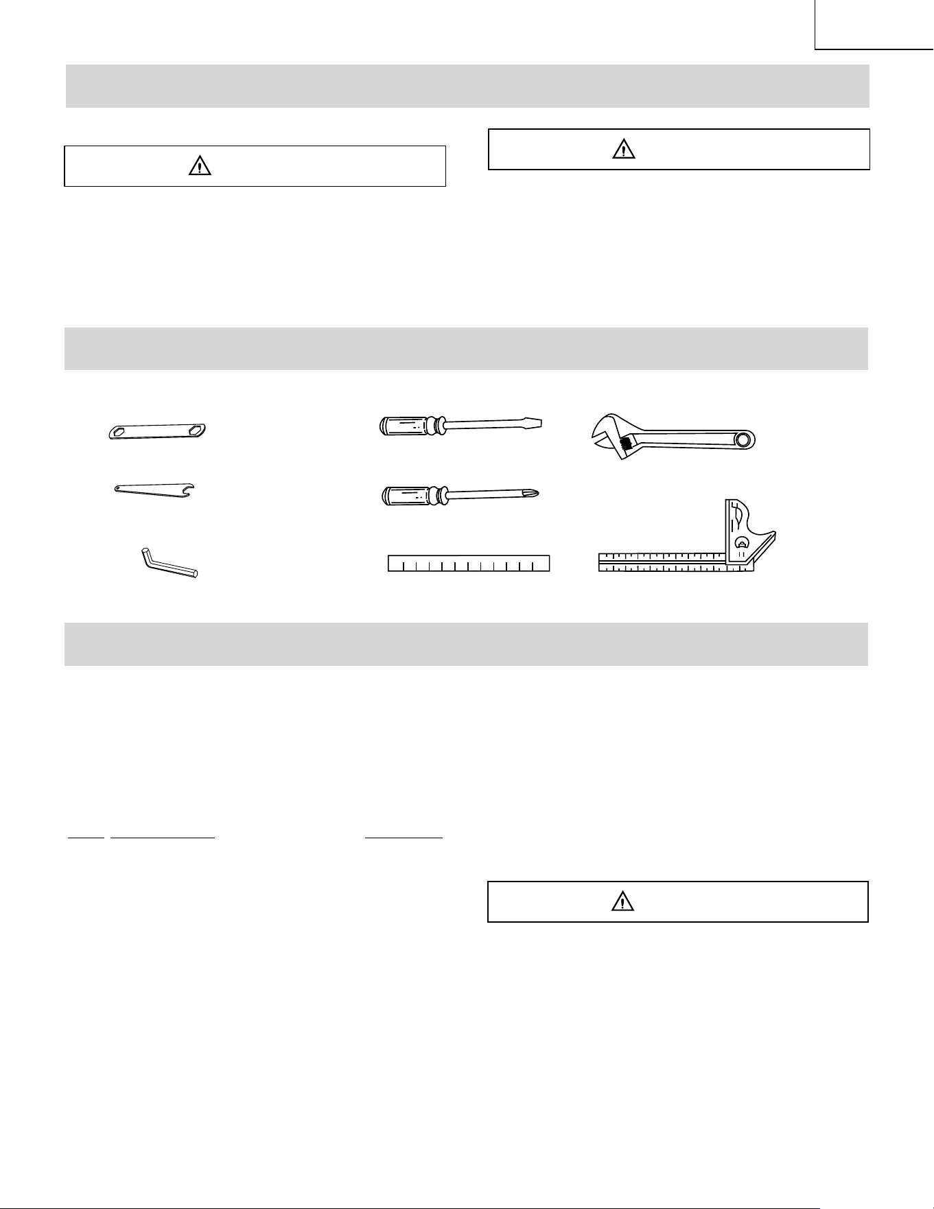
TOOLS NEEDED FOR ASSEMBLY
CARTON CONTENTS
ITEM
DESCRIPTION QUANTITY
A
Table saw assembly 1
B
Blade 1
C
Blade wrenches 2
D
Miter gauge 1
E
Hex key 1
F Bolt, flat washer, toothed washer,
oval washer, spring washer
1 each
G Blade guard and splitter assembly
1
H
Rip fence 1
I
Rear table extension 1
J
Rear table extension tube 2
K
Location seat 4
L
Dome nuts 2
M Handwheels
2
N
Table extension 1
O
Dust bag 1
P
Parallel washer hardware 1
STAND:
Q Stand assembly 1
R Hex. head bolts 4
S Flat washers 4
T Roller wheels 2
U Square neck bolts 2
V Nuts 2
W Support rod 1
X Batteries 2
Not Supplied
Medium Screwdriver
#2 Phillips Screwdriver
Straight Edge
Adjustable Wrench
Combination Square
Supplied
Wrench
3 mm Hex Wrench
Wrench
If any part is missing or damaged, do not attempt
to assemble the table saw, plug in the power cord,
or turn the switch ON until the missing or damaged
part is obtained and is installed correctly.
NOTE: To make assembly easier, keep contents of box
together. Apply a coat of automobile wax to the table.
Wipe all parts thoroughly with a clean dry cloth. This will
reduce friction when pushing the workpiece. To avoid
injury, the styrofoam block should be removed between
the motor and the table.
WARNING
– 8 –
English
UNPACKING YOUR TABLE SAW
A
D
B
C
I
F
H
J
S
L
M
N
O
P
Q
R
X
E
G
K
T
U
V
W
OFF
ON
– 9 –
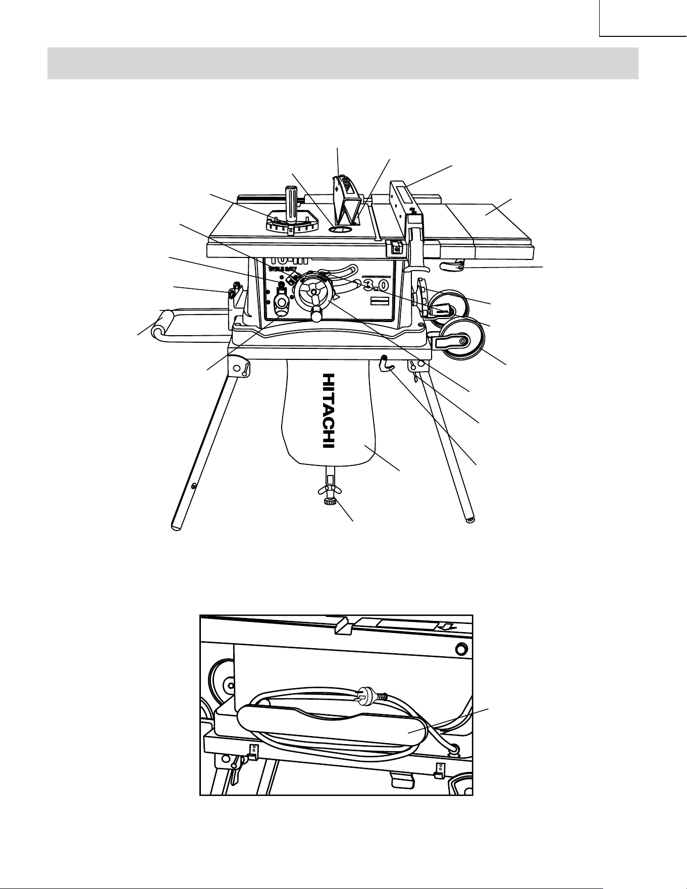
English
Rip fence
Miter gauge
Overload reset switch
Blade elevation handwheel
Cutting line indicator
Blade bevel lock knob
Side table extension
Blade guard with LED lighting
KNOW YOUR TABLE SAW
Support rod
Stand wheel
Cord wrap
Bevel angle pointer & scale
The Front of Table Saw
The Rear of Table Saw
Miter gauge storage
Stand handle
ON/OFF switch with key
Stand hook
Lock lever
Blade tilting handwheel
Extension wing
locking lever
Dust Bag
Fence storage
Table Insert
OFF
ON

– 10 –
English
NOTE: Do not over tighten bolts holding saw to
stand. This will damage the saw base.
5. Carefully set the saw in its upright position on a
clean level surface.
6. Thread the support rod (10) into the socket (11) at the
rear of stand. Adjust the adjustable foot (12) properly.
Fig. A-2
FOLDING THE TABLE SAW/STAND (FIG. A-1, A-3)
1. Release the lever of the narrower leg set and keep
the lever on top. Hold the table and lift the saw up just
above the ground and fold up the narrower leg set.
NOTE: The narrow leg set can be held by a “spring
clip”
.
2. Then reposition on the saw onto the ground. Release
the lever of the wider leg and keep the lever on top
set then fold the leg set up into position.
3. Then fix the legs with stand hook.
SETTING UP THE TABLE SAW/STAND (FIG. A-3)
1. Release the stand hook.
2. Unfold the wider leg set and lock the lever in place.
3. Put down the wider leg set on the ground, lift the saw
up and unfold the narrower leg set.
4. Pull the lever downward and lock into place.
NOTE: Make sure the saw is locked in position
securely before operation.
Fig. A-3
ESTIMATED ASSEMBLY TIME 25~40 MINUTES
FOLDING THE STAND (FIG. A-1)
1. Release the stand hook (1).
2. Unfold the wider leg set (2). Pull the lever (3)
downward and push it to lock in place. Then, put
down the wider leg set on the ground.
3. Lift the stand up and unfold the narrower leg set (4).
4. Pull the lever downward and push it to lock in place.
NOTE: Make sure the stand is locked securely.
Fig. A-1
ASSEMBLING THE ROLLER WHEEL (FIG. A-1)
Attach the roller wheel (7) to roller wheel bracket using
square neck bolt (8) and nut (9) as shown.
INSTALLING THE DUST BAG (FIG. A-1)
1. Place the dust bag (6) around the neck of the dust
chute and tie the dust bag by pulling the string tight
and secure with the spring-loaded tie clip.
NOTE: Do not use this saw to cut and sand metal.
The hot chips or sparks may ignite sawdust or the
bag material.
ASSEMBLING TABLE SAW TO STAND (FIG. A-1,A-2)
1. Place stand on level surface and adjust front right
adjustable stand pad (5) to make stand stable.
2. Place table saw on the top of stand aligning holes in
base with holes in s tand.
3. Insert four hex. head bolts (6) through flat washer
and holes in base and s tand.
4. Tighten all four bolts .
ASSEMBLY AND ADJUSTMENTS
1
2
4
6
5
3
10
11
8
7
9
6
6
12
FOLDING
SET-UP
1
2
1
2
3
OFF
ON
– 11 –
English
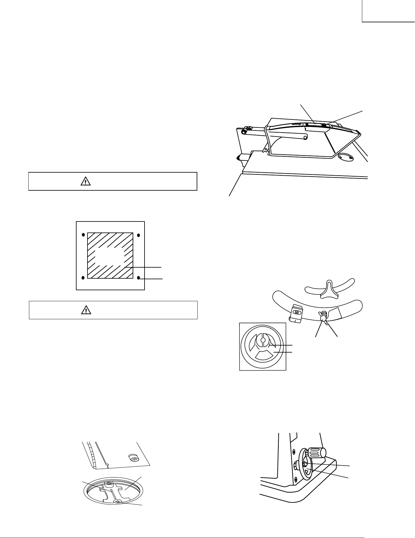
INSTALLING BATTERY FOR LED LIGHTING SPACE
(FIG. D)
1. Open the cover (1) of battery box on the top of blade
guard.
2. Install 2 pieces of 1.5V 3A batteries into the battery
box in right direction.
3. Close the cover.
4. Turn on the switch (2) to check the LED lighting.
Fig. D
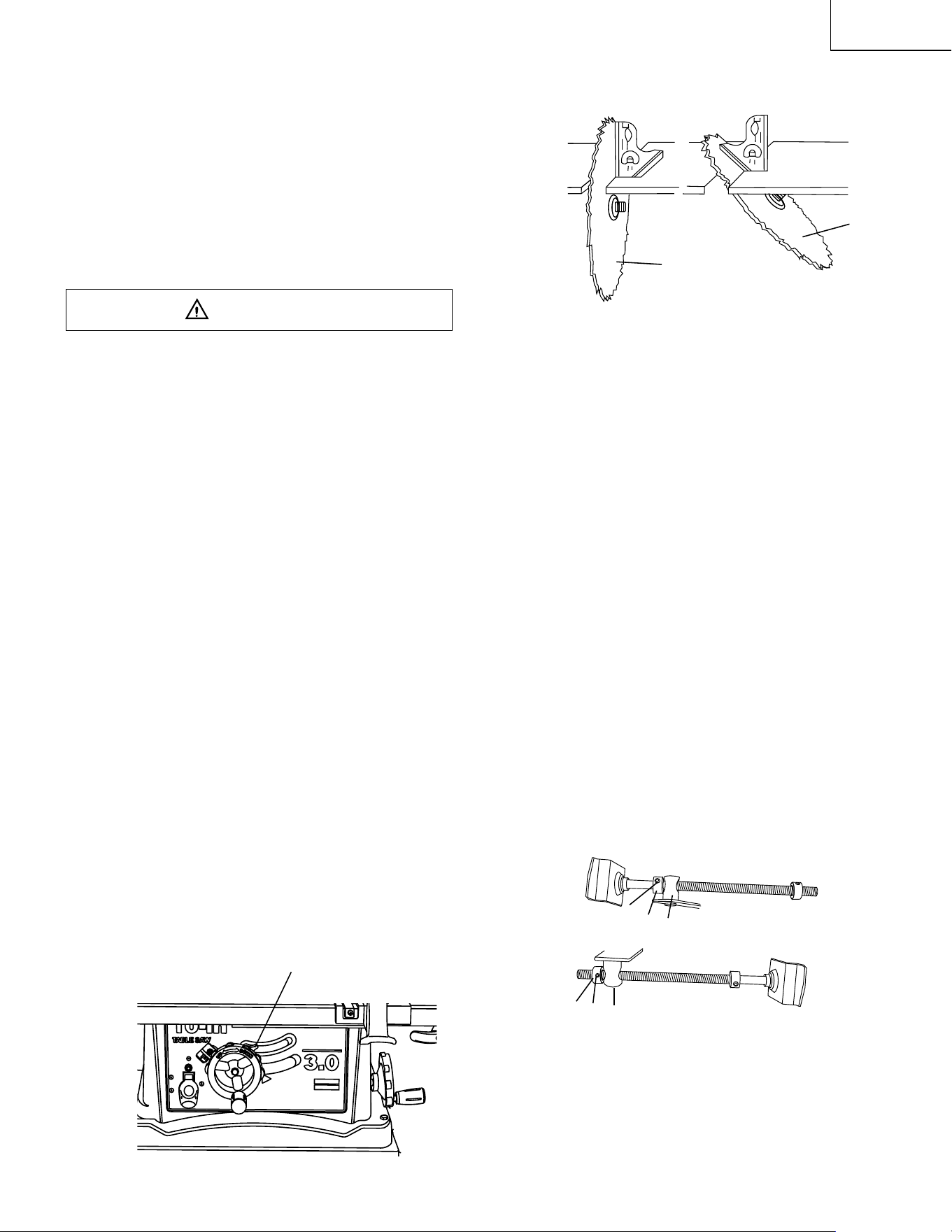
BLADE RAISING HANDWHEEL (FIG. E, F)
1. Attach the handwheel (1) to the elevation screw (2)
at the front of the saw. Make sure the slots (3) in the
hub of the handwheel engage with the pins (4).
(Fig. E)
2. Attach and tighten the dome nut (5) at the end of the
shaft (Fig. F).
Fig. E
BLADE TILTING HANDWHEEL (FIG. F)
1. Attach the other handwheel (6) to the blade tilting
screw on the side of the saw in the same manner as
above.
2. Attach and tighten the handwheel dome nut (5).
Fig. F
SAW MOUNTED TO WORK SURFACE (FIG. B)
1. If the leg set will not be used, the saw must be
properly secured to a sturdy workbench using the
four mounting holes at the base of the saw.
2. The surface of the table where the saw is to be
mounted must have a hole large enough to facilitate
sawdust fall-through and removal.
3. Square the saw on the mounting surface and mark
the location of the four 3/8” (9.5mm) mounting holes
(1).
4. Drill 3/8” (9.5mm) hole into the mounting surface.
5. Mark an 11” (279.4mm) square (2) centered between
the four mounting holes (1).
6. Cut out and remove the square.
7. This opening will allow sawdust to fall through the
saw base.
8. Place the saw on the work surface, and align the
mounting holes of the saw with those drilled through
the surface.
9. Fasten the saw to the work surface.
Do not operate this machine on the floor. This is
very dangerous and may cause serious injury.
Fig. B
Failure to provide the sawdust fall-through hole will
cause sawdust to build up in the motor area, which may
result in fire or cause motor damage.
KEEPING THE AREA CLEAN
1. Sawdust and wood chips that fall from under the saw
will accumulate on the floor.
2. Make it a practice to pick up and discard this dust
when you have completed cutting.
ADJUSTING THE CUTTING LINE INDICATOR (FIG. C)
1. Take off the cover (1) by loosening screws (2).
2. Adjust the pointer (3) to align to the blade.
3. Mount the cover on the table to fix the pointer.
NOTE: The pointer was set up to align to the right
side of the blade when packing.
Fig. C
WARNING
WARNING
3
4
2
1
1
2
SQUARE
CUTOUT
3
2
1
5
6
1
2
– 12 –
English
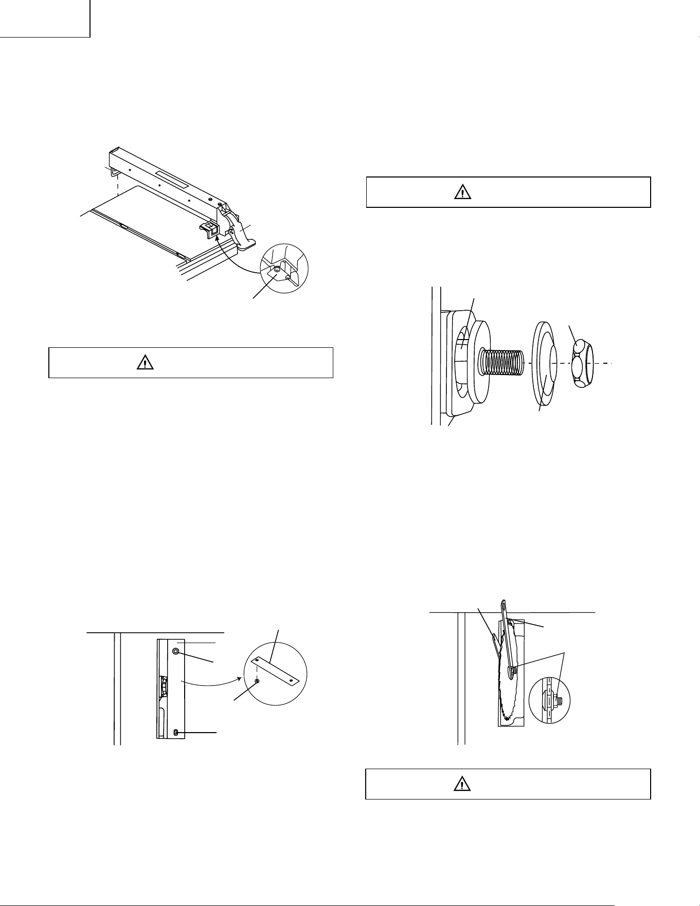
RIP FENCE (FIG. G)
1. Lift upward on the rip fence handle (1) so the rear
holding clamp (2) is fully extended.
2. Place the rip fence on the saw table, and attach the
set plate (3) under the fence handle(1) to the rail first.
3. Push down on the fence handle (1) to lock.
Fig. G
INSTALLING AND CHANGING THE BLADE (Fig. H, I,
J)
• To avoid injury from an accidental start, make
sure the switch is in the OFF position and the
plug is not connected to the power source outlet.
• To avoid serious injury, the rear of the table insert
must be level with the table. To adjust rear of
table insert, adjust the screw (3) in or out until
the rear of the insert is level to or slightly above
the table. To raise the insert, turn the screw
counterclockwise, to lower the insert, turn the
screw clockwise. NOTE: A rubber adjusting
spacer (4) is provided under rear of insert for this
purpose.
1. Remove the table insert (1) by removing the two
screws (2, 3). Be careful not to lose the rubber
adjusting spacer (4) that is on the back screw (3)
beneath the table insert (Fig. H).
Fig. H
2. Raise the blade arbor (4) (Fig. G) to the maximum
height by turning the blade raising handwheel
counterclockwise.
3. Place the open-end wrench jaws on the flats of the
saw arbor to keep the arbor from turning. (Fig. H)
and place the box-end wrench (8) on the arbor nut
(5), and turn counterclockwise.
4. Remove the arbor nut (5) and flange (6), remove
blade.
5. Install the saw blade onto the arbor with the BLADE
TEETH POINTING TOWARD THE FRONT OF THE
SAW.
6. Install the flange (6) against the blade and thread
the arbor nut (5) as far as possible by hand. Ensure
that the blade is flush against the inner side of the
blade flange.
To avoid possible injury and damage to the workpiece
be sure to install the blade with the teeth pointing toward
the front of table in the direction of the rotation arrow on
the blade guard.
Fig. I
7. To tighten the arbor nut (5) place the open-end
wrench jaws on the flats of the saw arbor to keep the
arbor from turning. (Fig. J )
8. Place the box-end wrench (8) on the arbor nut (5),
and turn clockwise (to the rear of the saw table).
9. Replace the blade insert in the table recess, insert
the screws through the front and rear holes and
tighten, remembering the rubber adjusting spacer
under the rear of the insert and leveling the rear of
the insert to the table.
Fig. J
To avoid injury from a thrown workpiece, blade parts, or
blade contact, never operate saw without the proper
insert in place. Use the saw blade insert when sawing.
Use the dado head insert when using a dado.
WARNING
WARNING
5
6
4
5
7
8
WARNING
1
3
2
1
4
1
3
2
– 13 –
English
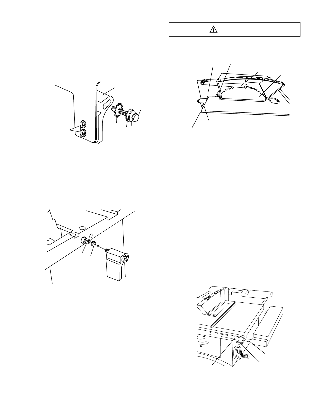
BLADE GUARD ASSEMBLY (FIG. K, L, M)
1. Set the blade to maximum height and the tilt to zero
degrees on the bevel scale with the handwheels.
Lock the blade lock knob.
2. Place the external toothed lock washer (1), a steel
flat washer (2) and a spring washer (10) onto the
long hex head bolt (3). Insert the bolt into the splitter
bracket (4) as shown. (Fig. K)
Fig. K
3.
Place the oval washer (5) on the pivot rod (6). (Fig.
L)
4. Install the bracket assembly (4) at the rear of the saw
table and snugly – do not tighten. Thread the bolt (3)
into the internally threaded pivot rod.
NOTE: The splitter is removed from the illustration for
clarity.
Fig. L
5. Position the blade guard arm (7) to the rear of the
table.
6. Using a straight edge, check to see if the blade
guard splitter (8) is aligned with the saw blade (9).
7. If straightening adjustment is necessary, loosen the
bolt (3) and shift the splitter assembly to right or left,
or rotate.
8. When the splitter is properly aligned with the saw
blade, tighten the bolt tightly.
9. If height adjustment is necessary, loosen the bolts
(11) and raise the splitter assembly to the desired
height and tighten the bolts. (Fig. K)
10. NOTE: The splitter must always be correctly aligned
so that the cut workpiece will pass on either side
without binding or twisting to the side.
Improper splitter alignment can cause “kickback” and
serious injury.
Fig. M
INSTALLING TABLE SIDE EXTENSION (FIG. N)
1. Identify the right hand table extension.
NOTE: For illustration purposes the view in Fig. N
looks “through” the saw table to the under side of the
table. The right hand table extension is the one with
the measuring scale (1) visible from the front of the
saw when it is installed to the right hand side of the
saw table (Fig. N).
2. Open both front and rear cam locking levers (2) on
the right hand side of the saw base by pulling them
out from the cam locking assemblies (4).
3. Insert the table extension mounting tubes (3) into the
two matching holes in the cam lever assemblies.
NOTE: Make sure the front mounting tube has the
measuring scale visible from the front of the saw.
4. Slide the table extension toward the table until it
rests against the saw table.
5. Lock both cam locking levers by pushing them in
toward the cam locking lever assemblies.
Fig. N
WARNING
1
3
4
2
10
11
5
6
3
8
7
9
Kickback pawl
3
4
2
– 14 –
English
INSTALLING TABLE SIDE EXTENSIONS- cont’d (FIG. O)
6. Snap one short location seat (5) over the end of the
rear table extension tube (3). Make sure the locating
pin (6) in the location seat fits into the matching hole
in the extension tube (Fig. O).
NOTE: Install location seat on front table extension
tube.
NOTE: For illustration purposes the view in Fig. O
looks “through” the saw table to the under side of the
table.
Fig. O
INSTALLING REAR TABLE EXTENSION (FIG. P)
1. Place the rear table extension onto the two rear table
extension tubes (1).
2. Snap two long location seats (4) over the two rear
table extension tubes (1). Make sure the locating pin
in the location seat fits into the matching hole (5) in
the extension tube.
3. Insert rear table extension tubes (1) into the two
holes in the rear of the saw table (3) and into
extension tube brackets under the table.
4. Position rear table support so instruction labels are
up.
5. Snap one short location seat (4) over the end of the
left rear table extension tube (1). Make sure the
locating pin in the location seat fits into the matching
hole in the extension tube.
Fig. P
6
5
3
3
4
5
1
ADJUSTING REAR TABLE EXTENSION
1. Rear table extension should be positioned as close
as possible to the rear of the table when ripping short
workpieces.
2. Rear table extension should be pulled out fully until
the location seat prevents it from moving outward
when ripping long workpieces that require extra
support as you are completing the cut.
RIP FENCE ADJUSTMENT (FIG. Q)
1. The fence (1) is moved by lifting up on the handle (2)
and sliding the fence to the desired location. Pushing
down on the handle locks the fence in position.
2. Position the fence on the right side of the table, and
along one edge of the miter gauge grooves.
3. Lock the fence handle. The fence should be parallel
with the miter gauge groove.
4. If adjustment is needed to make the fence parallel to
the groove, do the following:
• Loosen the two screws (4) and lift up on the
handle (2).
• Hold the fence bracket (5) firmly against the front
of the saw table. Move the far end of the fence
until it is parallel with the miter gauge groove.
• Tighten both screws and push the handle to lock.
5. If fence is loose when the handle is in the locked
(downward) position, do the following:
• Move the handle (2) and then remove cover (3)
pward and turn the adjusting nut (6) clockwise until
the rear clamp is snug. Do not turn the adjusting
screw more than 1/4 turn at a time.
• Over-tightening the adjusting screw will cause the
fence to come out of alignment.
Failure to properly align fence can cause “kickback” and
serious injury.
Fig. Q
WARNING
6
1
4
5
2
3
– 15 –
English
RIP FENCE INDICATOR ADJUSTMENT (FIG. Q)
1. The rip fence indicator (6) points to the measurement
scale (8). The scale shows the distance from the side
of the fence to nearest side of the blade.
2. Measure the actual distance with a rule. If there is a
difference between the measurement and the
indicator, adjust the indicator (6).
3. Loosen the screw (7) and slide the indicator to the
correct measurement on the scale. Tighten the screw
and remeasure with the rule.
To avoid injury from an accidental start, make sure the
switch is in the OFF position and the plug is not
connected to the power source outlet.
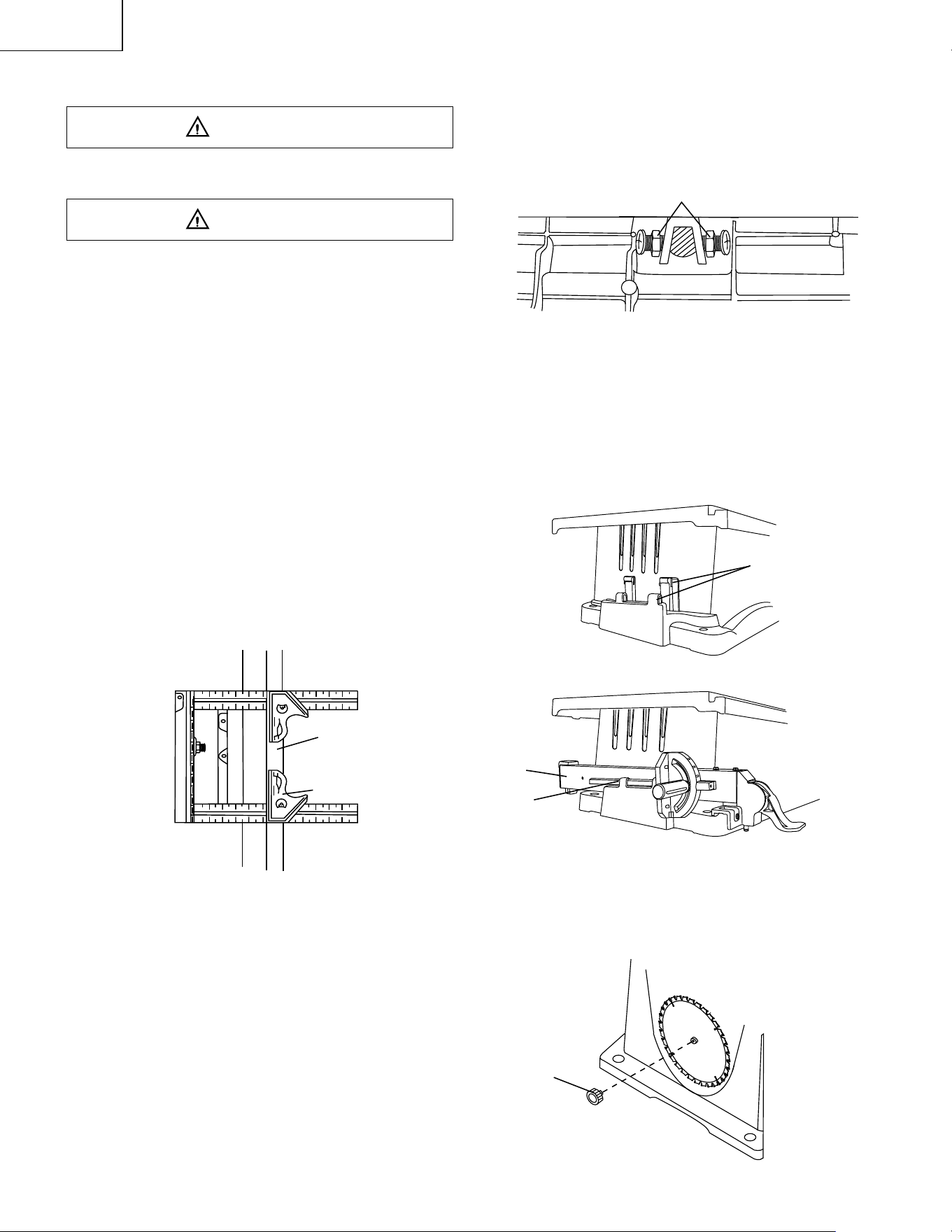
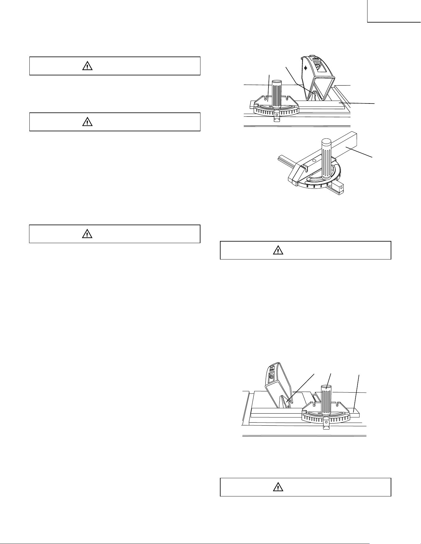
ADJUSTING THE 90° AND 45° POSITIVE STOPS
(FIG. Q-1, Q-2, Q-3)
Your saw has positive stops that will quickly position the
saw blade at 90° to the table. Make adjustments only if
necessary.
90° (0°) Stop
1. Disconnect the saw from the power source.
2. Turn the blade elevation handwheel and raise the
blade to the maximum elevation.
3. Loosen the blade bevel lock knob (2) and move the
blade to the maximum vertical position. Tighten the
lock knob (2).
4. Place a combination square on the table and against
the blade (1) to determine if the blade is 90° to the
table. (Fig. Q-2)
5. If the blade is not 90° (0°) to the table, loosen the
two set screws (4), located on the bottom of the table
saw, (Fig. Q-3) with the hex key, and back off the
collar.
6. Loosen the bevel lock knob. Turn the blade tilting
handwheel to move the blade until it is 90° (0°) to the
table.
7. Adjust the collar (5) so it contacts the bracket (3)
when the blade is 90° (0°) to the table. Tighten the
two set screws (4).
Fig. Q-1
Fig. Q-2
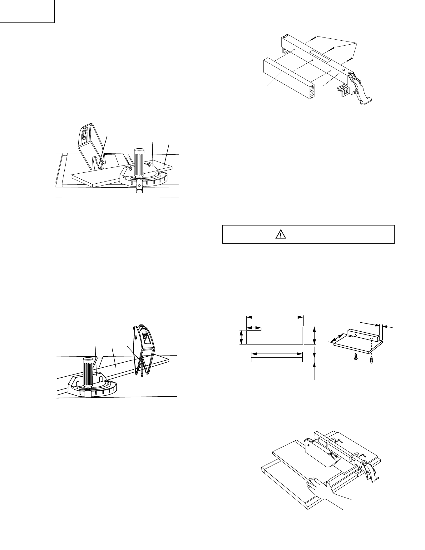
45° Stop
1. With the blade in the upright 90° position, loosen the
bevel lock knob and move the blade to the 45°
position as far as it will go.
2. Place the combination square on the table as shown
in (Fig. Q-2) to check if the blade is 45° to the table.
3. If the blade is not 45° to the table, adjust the screw
(4) (Fig. Q-3) with a screw driver until the blade is 45
°
to the table.
4. Tighten the bevel lock knob.
5. Tighten the screw (4) until resistance is felt. Do not
overtighten.
BLADE TILT POINTER
1. When the blade is positioned at 90°, adjust the blade
tilt pointer to read 0° on the scale.
2. Loosen the holding screw, position pointer over 0°
and tighten the screw.
NOTE: Make a trial cut on scrap wood before making
critical cuts. Measure for exactness.
Fig. Q-3
WARNING
3
3
4
4
5
5
1
3
90°
45°
2
OFF
ON
– 16 –
English
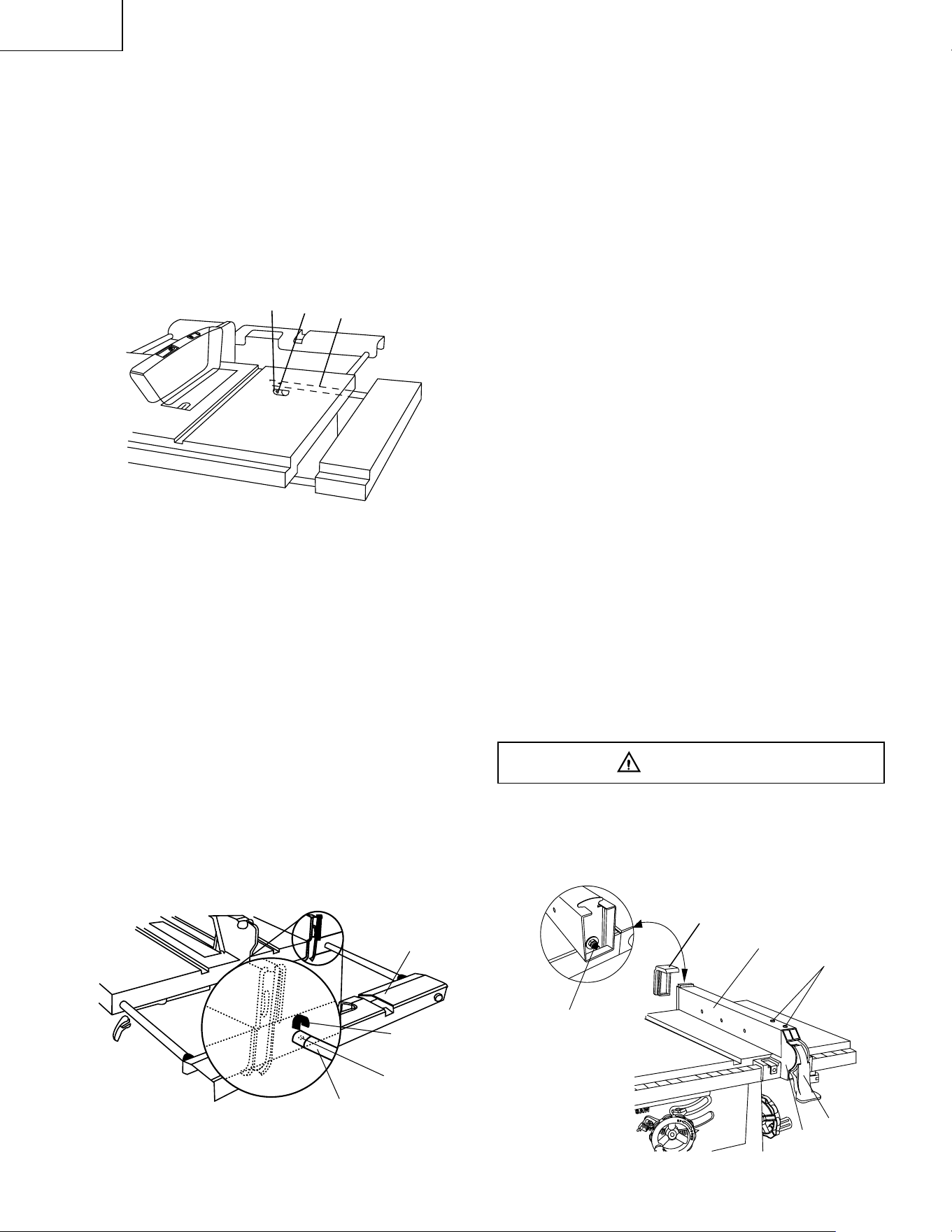
BLADE PARALLEL TO THE MITER GAUGE GROOVE
(FIG. R, S)
This adjustment was made at the factory, but it should
be rechecked and adjusted if necessary.
To prevent personal injury:
• Always disconnect plug from the power source when
making any adjustments.
• This adjustment must be correct or kickback could
result in a serious injury and accurate cuts can not
be made.
1. Remove the yellow switch key and unplug the saw.
2. Move the blade guard out of the way.
3. Raise the blade to the highest position and set at the
0° angle (90° straight up).
4 Select and mark, with a felt tip marker, a blade tooth
having a “right set”.
5. Place the combination square base (1) into the right
side miter gauge groove (2). (Fig. R)
6. Adjust the rule so it touches the front marked tooth
and lock ruler so it holds its position in the square
assembly.
7. Rotate the blade bringing the marked tooth to the
rear and about 1/2 inch above the blade.
8. Carefully slide the combination square to the rear
until the ruler touches the marked tooth.
9. If the ruler touches the marked tooth at the front and
rear position, no adjustment is needed at this time. If
not, perform adjustment procedure described in next
section.
Fig. R
ADDITIONAL BLADE ADJUSTMENTS (Fig. S)
The adjusting mechanism is located on top of blade
height adjusting handwheel under the tabletop. If the
front and rear measurements are not the same, adjust
the alignment by the mechanism as follows:
If the blade is partial to right side:
1. Loosen the two nuts (1) and the right side screw,
then adjust the left side screw.
2. Tighten the nuts (1) and the right screw and
remeasure, as described in steps 4 to 9 in the prior
section.
If the blade is partial to left side:
3. Loosen the two nuts (1) and the left side screw, then
adjust the right screw.
4. Tighten the nuts (1) and the left screw and
remeasure, as described in steps 4 to 9 in the prior
section.
5. Recheck blade clearance making sure that the
blade does not hit the table insert or other parts
when at the 90° and 45° settings.
Fig. S
STORAGE (FIG. T, T-1)
Rip fence and miter gauge
Storage brackets (1) for the rip fence (3) and miter
gauge (2) are located on the left side of the saw
housing.
NOTE:Adjust the miter gauge to 45
0
~60
0
before putting
to the storage.
Fig. T
Fig. T-1
Blade (Fig. T-2)
1. Loosen and remove the knob (1) on the right side of
the saw housing.
2. Place extra blades onto the arbor. Replace the knob
and tighten.
Fig. T-2
WARNING
WARNING
1
2
1
1
1
2
3
– 17 –
English
BASIC SAW OPERATIONS
RAISE THE BLADE (FIG. U)
To raise or lower the blade, turn the blade elevation
handwheel (1) to the desired blade height, and then
tighten the bevel lock knob (2) to maintain the desired
blade angle.
Fig. U
TILTING THE BLADE (FIG. U)
1. To tilt the saw blade for bevel cutting, loosen the lock
knob (2) and turn the tilting handwheel (3).
2. Tighten the lock knob (2) to secure.
ON/OFF SWITCH (FIG. V)
The ON / OFF switch has a removal key. With the key
removed from the switch, unauthorized and hazardous
use by children and others is minimized.
1. To turn the saw ON, insert key (1) into the slot in
the switch (2). Move the switch upward to the ON
position.
2. To turn the saw OFF, move the switch downward.
3. To lock the switch in the OFF position, grasp the end
(or yellow part) of the switch key (1) and pull it out.
4. With the safety switch key removed, the switch will
not operate.
5. If the safety switch key is removed while the saw is
running, it can be turned OFF but cannot be restarted
without inserting the safety switch key.
Fig. V
OPERATION
OVERLOAD PROTECTION (FIG. W)
This saw has an overload relay button (3) that resets the
motor after it shuts off due to overloading or low voltage.
If the motor stops during operation, turn the ON / OFF
switch to the OFF position. Wait about five minutes for
the motor to cool, push in on the reset button and turn
the switch to the ON position.
To avoid injury, the ON / OFF switch should be in the
OFF position and the plug removed from the power
source while the cool down takes place, to prevent
accidental starting when the reset button is pushed.
Overheating may be caused by misaligned parts or a
dull blade. Inspect your saw for proper setup before
using it again.
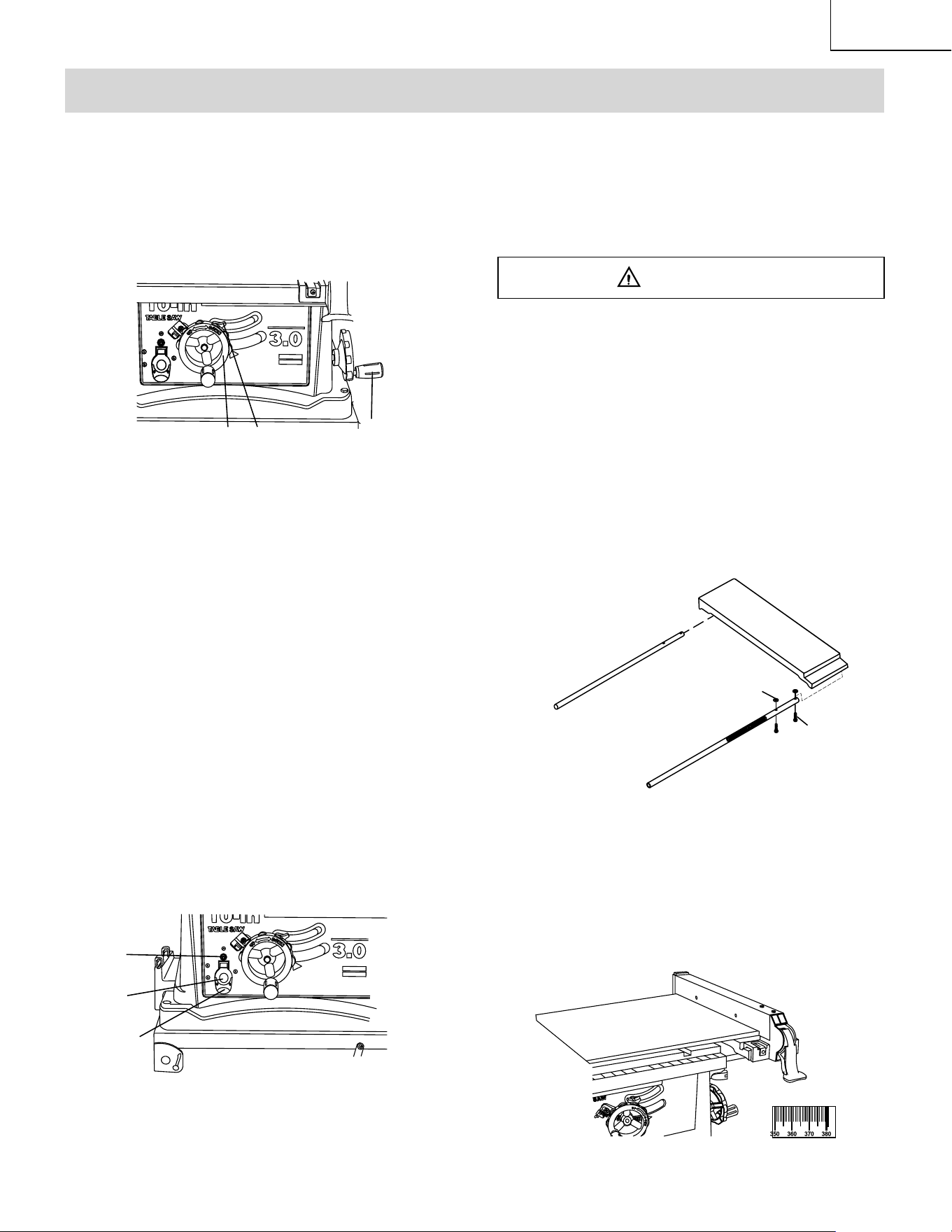
USING THE TABLE EXTENSION (FIG. X, X-1)
If the table extension is not parallel with the table.
Remove the bolts (1) and position the parallel washers
(2) between the table extension and tube until it is
parallel with the table, then tighten the bolts.
NOTE: Parallel washers (2) see page 7 for table of
loose parts ITEM: P.
Fig. X
NOTE: Move and lock the fence to the 381mm left or
right side scale. The fence is now clear of the table.
1. Release the extension lock handles.
2. Slide the extension out until the correct measurement
is displayed on the tube scale. The user sights the
scale off the edge of the table.
3. Tighten all extension lock handles.
Fig. X-1
WARNING
1
2
3
1
2
1
Right side scale of table extension
OFF ON
2
3
OFF
ON
– 18 –
English
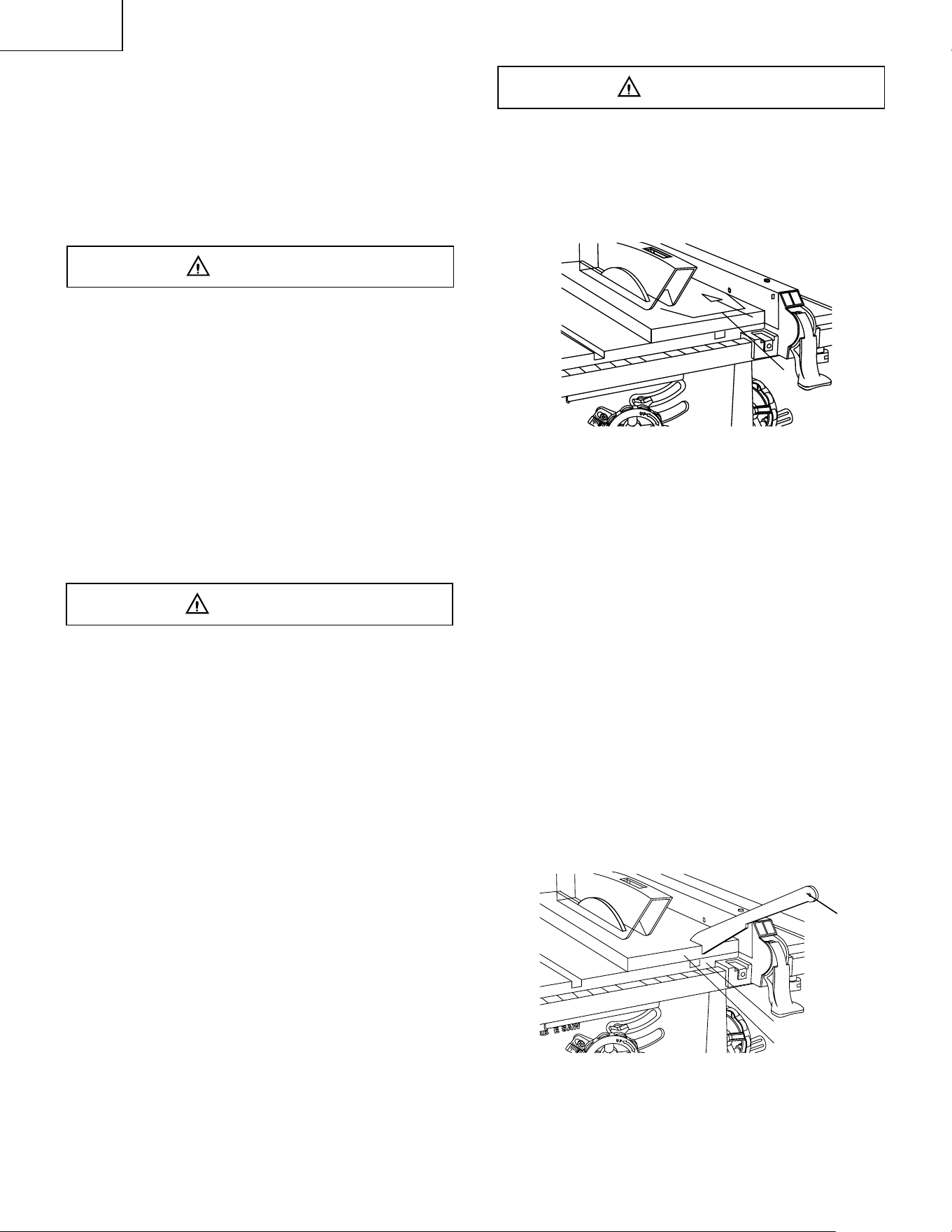
AVOID KICKBACK by pushing forward on the section
of the workpiece that passes between the blade and the
fence. Never perform any freehand operations.
Fig. Y
NOTE: Always use a push stick. When width of the rip is
narrower than 2” (51mm) the push stick cannot be used
because the guard will interfere…therefore, use the
auxiliary fence so the push stick can be used as shown
on page 23.
7. Keep your thumbs off the table top. When both of
your thumbs touch the front edge of the table (2),
finish the cut with a push stick. To make an additional
push stick, use the pattern on page 23.
8. The push stick (3) should always be used. (Fig. Z)
9. Continue pushing the workpiece with the push
stick (3) until it passes through the blade guard and
clears the rear of the table.
10.Never pull the piece back when the blade is turning.
Turn the switch OFF. When the blade completely
stops, you can then remove the workpiece.
Fig. Z
CUTTING OPERATIONS
There are two basic types of cuts: ripping and
crosscutting. Ripping is cutting along the length and the
grain of the workpiece. Crosscutting is cutting either
across the width or across the grain of the workpiece.
Neither ripping nor crosscutting may be done safely
freehand. Ripping requires the use of the rip fence, and
crosscutting requires the miter gauge.
Before using the saw each and every time, check
the following:
1. The blade is tightened to the arbor.
2. The bevel angle lock knob is tight.
3. If ripping, the fence is locked into position & is
parallel to the miter gauge groove.
4. The blade guard is in place and working properly.
5. Safety glasses are being worn.
The failure to adhere to these common safety rules, and
those printed in the front of this manual, can greatly
increase the likelihood of injury.
RIPPING (FIG. Y, Z)
To prevent serious injury:
• Never use a miter gauge when ripping.
• Never use more than one rip fence during a single
cut.
• Do not allow familiarity or frequent use of your table
saw to cause careless mistakes. Remember that
even a careless fraction of a second is enough to
cause a severe injury.
• Keep both hands away from the blade and clear from
the path of the blade.
• The workpiece must have a straight edge against the
fence and must not be warped, twisted, or bowed
when ripping.
1. Remove the miter gauge and store it in the “storage”
compartment in the base of the saw.
2. Secure the rip fence to the table.
3. Raise the blade so it is about 1/8” higher than the top
of the workpiece.
4. Place the workpiece flat on the table and against the
fence. Keep the workpiece away from the blade.
5. Turn the saw ON and wait for the blade to come to
full speed.
6. Slowly feed the workpiece into the blade by pushing
forward only on the workpiece section (1) that will
pass between the blade and the fence. (Fig. Y)
WARNING
WARNING
WARNING
1
2
1
3
– 19 –
English
with the proper operation of the sawblade guard. When
cutting long workpieces, you can make a simple outfeed
support by clamping a piece of plywood to a sawhorse.
Fig. AA
Fig. AA-1
BEVEL CROSSCUTTING (FIG. BB) 0°~45° BLADE
BEVEL & 90° MITER ANGLE
This cutting operation is the same as crosscutting
except the blade is at a bevel angle other than 0°.
Always work to the right side of the blade during
this type of cut. The miter gauge must be in the right
side groove because the bevel angle may cause the
blade guard to interfere with the cut if used on the
left side groove.
1. Adjust the blade (1) to the desired angle, and tighten
the blade bevel lock knob.
2. Tighten miter lock handle (2) at 90°.
3. Hold workpiece (3) firmly against the face of the miter
gauge throughout the cutting operation.
Fig. BB
COMPOUND MITER CROSSCUTTING (FIG. CC)
0°~45° BLADE BEVEL & 0°~45° MITER ANGLE
This sawing operation is combining a miter angle with a
bevel angle.
Always work to the right side of the blade during
this type of cut. The miter gauge must be in the right
BEVEL RIPPING
This cut is the same as ripping except the blade bevel
angle is set to an angle other than “0°”.
Cut only with the workpiece and the fence on the right
side of the blade.
RIPPING SMALL PIECES
Avoid injury from the blade contact. Never make through
saw cuts narrower than 1/2” (12.7mm) wide.
1. It is unsafe to rip small pieces. Instead, rip a larger
piece to obtain the size of the desired piece.
2. When a small width is to be ripped and your hand
cannot be safely put between the blade and the rip
fence, use one or more push sticks to move the
workpiece.
CROSSCUTTING (FIG. AA)
To prevent serious injury:
• Do not allow familiarity or frequent use of your table
saw to cause careless mistakes. Remember that
even a careless fraction of a second is enough to
cause a severe injury.
• Keep both hands away from the blade and the path
of the blade.
1. Remove the rip fence and place the miter gauge in
the left side groove.
2. Adjust the blade height so it is 1/8” (3.18mm) higher
than the top of the workpiece.
3. Hold the workpiece firmly against the miter gauge
with the blade path in line with the desired cut
location. Move the workpiece to one inch distance
from the blade.
4. Start the saw and wait for the blade (1) to come up to
full speed.
5. Keep the workpiece (2) against the face of the miter
gauge (3) and flat against the face of the gauge and
flat against the table. Then slowly push the workpiece
through the blade. (Fig. Y)
6. Do not try to pull the workpiece back with the blade
turning. Turn the switch OFF, and carefully slide the
workpiece out when the blade is completely stopped.
USING WOOD FACING ON THE MITER GAUGE
(FIG. AA-1)
Slots are provided in the miter gauge for attaching an
auxiliary facing (1) to make it easier to cut very long or
short pieces. Select a suitable piece of smooth wood,
drill two holes through it and attach it to the miter gauge
with screws. Make sure the facing does not interfere
WARNING
1
2
3
1
1
3
2
WARNING
WARNING
WARNING
WARNING
– 20 –
English
side groove because the bevel angle may cause the
blade guard to interfere with the cut if used on the
left side groove.
1. Set the miter gauge (3) to the desired angle.
2. Place the miter gauge in the right side groove of the
table.
3. Set the blade (1) bevel to the desired bevel angle
and tighten the blade bevel lock knob.
4. Hold workpiece (2) firmly against the face of the
miter gauge throughout the cutting operation.
Fig. CC
MITERING (FIG. DD) 0°~45° MITER ANGLE
This sawing operation is the same as crosscutting
except the miter gauge is locked at an angle other
than 90°.
1. Set the blade (1) to 0° bevel angle and tighten the
blade bevel lock knob.
2. Set the miter gauge (3) at the desired miter angle
and lock in position by tightening the miter gauge
locking handle.
3. Hold the workpiece (2) firmly against the face of the
miter gauge throughout the cutting operation.
Fig. DD
USING WOOD FACING ON THE RIP FENCE (FIG. EE)
When performing some special cutting operations, add
a wood facing (1) to either side of the rip fence (2).
1 . Use a smooth straight 3/4” (19 mm) thick wood
board (1) that is as long as the rip fence.
2. Attach the wood facing to the fence with wood screw
(3) through the hole in the fence. A wood fence
should be used when ripping material such as thin
paneling to prevent the material from catching
between the bottom of the fence and the table.
Fig. EE
AUXILIARY FENCE (FIG. FF)
Making the base:
• Start with a piece of 3/8” (9.5mm) plywood at least
5-1/2” (140mm) wide or wider and 30” (762mm) long
or longer.
• Cut the piece to shape and size shown:
Making the side:
• Start with a piece of 3/4” (19.1mm) plywood at least
2-3/8” (60mm) wide or wider and 27” (686mm) long
or longer.
• Cut the piece to shape and size shown:
Putting it together:
• Put the pieces together, as shown:
Make sure the screw heads do not stick out from the
bottom of the base, they must be flush or recessed.
The bottom must be flat and smooth enough to rest
on the saw table without rocking.
Fig. FF
Attach auxiliary fence to rip fence with two “C”
clamps (Fig. GG)
Fig. GG
30” (762mm)
2-5/8” (67mm)
3-1/2” (89mm)
3/8” (9.5mm) Thick plywood base
27” (686mm)
3/4” (19mm) Thick plywood side
5-1/2” (140mm)
2-3/8” (60mm)
4-3/4” (121mm)
1-1/4” (32mm)
WARNING
3
2
1
2
1
3
1
2
3
– 21 –
English
Fig. HH
Place a small amount of dry lubricant on the bevel gear
(2). The screw rod (1) must be kept clean and free of
sawdust, gum, pitch, and other contaminants for smooth
operations.
If excessive looseness is observed in any parts of the
blade raising mechanism or tilting mechanism, contact
Hitachi Authorized Service Center immediately.
LUBRICATION
All motor bearings are permanently lubricated at the
factory and require no additional lubrication.
On all mechanical parts of your table saw where a pivot
or threaded rod are present, lubricate using graphite or
silicone. These dry lubricants will not hold sawdust as
would oil or grease.
MAINTENANCE
MAINTAINING YOUR TABLE SAW
GENERAL MAINTENANCE
For your own safety, turn the switch OFF and remove
the switch key. Remove the plug from the power source
outlet before maintaining or lubricating your saw.
1. Clean out all sawdust that has accumulated inside
the saw cabinet and the motor.
2. Polish the saw table with an automotive wax to keep
it clean and to make it easier to slide the workpiece.
3. Clean cutting blades with pitch and gum remover.
4. A worn, cut, or damaged power cord should be
replaced immediately.
All electrical or mechanical repairs should be attempted
only by a trained repair technician. Contact Hitachi
Authorized Service Center for service. Use only identical
replacement parts. Any other parts may create a hazard.
5. Use liquid dish washing detergent and water to clean
all plastic parts.
NOTE: Certain cleaning chemicals can damage
plastic parts.
6. Avoid use of cleaning chemicals or solvents,
ammonia and household detergents containing
ammonia.
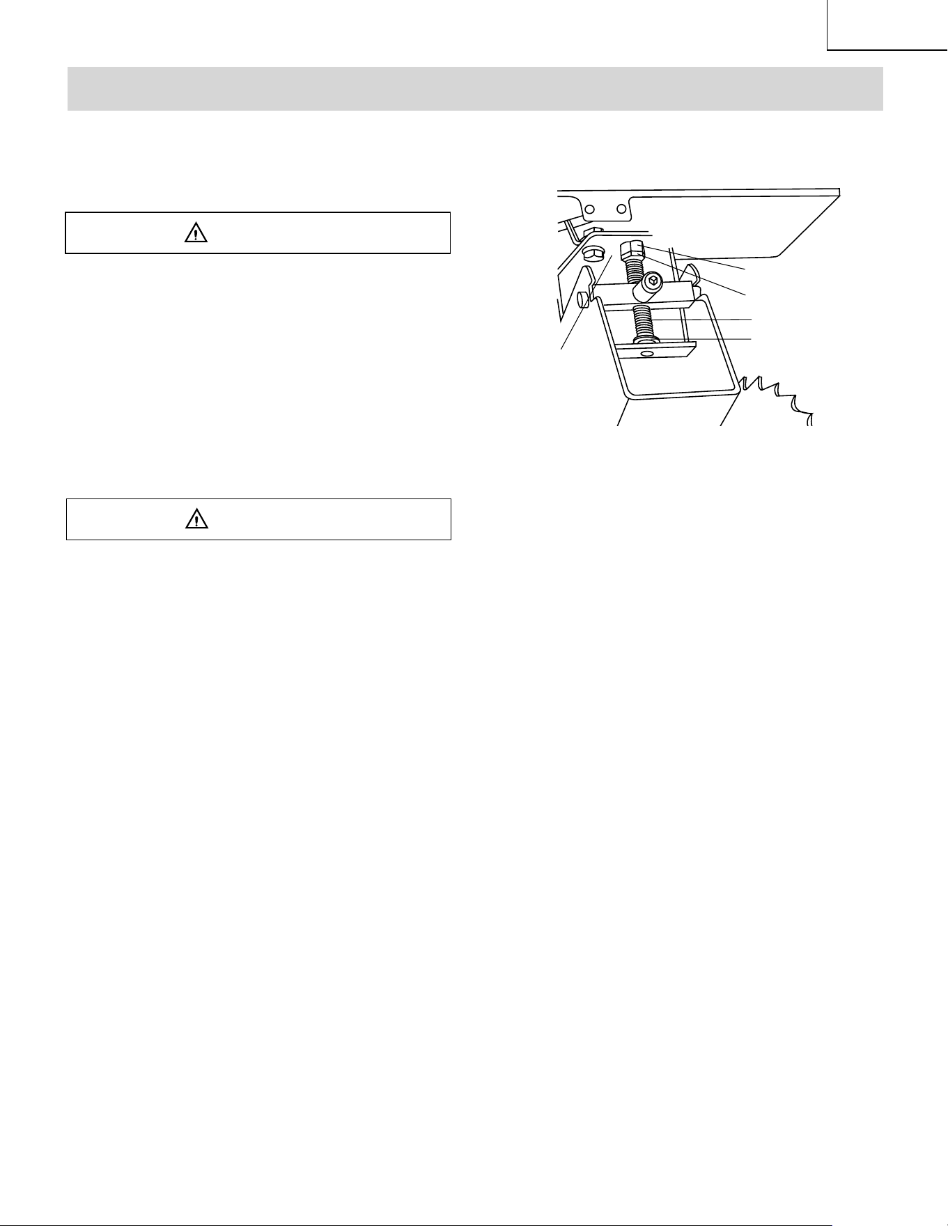
BLADE RAISING AND TILTING MECHANISM (FIG.
HH)
After each five hours of operation, the blade raising
mechanism and tilting mechanism should be checked
for looseness, binding, or other abnormalities. With the
saw dis-connected from the power source, turn the saw
upside down and alternately pull upward and downward
on the motor unit. Observe any movement of the motor
mounting mechanism. Looseness or play in the blade
raising screw (1) should be adjusted as follows:
1. Using a wrench, loosen nut (2).
2. Adjust nut (3) until it is finger-tight against the bracket
(4), then back off the nut (3) 1/6 turn.
3. Tighten nut (2) with the wrench, while holding nut (3)
in place. Maximum allowable play of screw rod (1) is
0.16” (4 mm).
WARNING
WARNING
1
2
3
5
4

– 22 –
English
TROUBLESHOOTING GUIDE
WARNING
To avoid injury from an accidental start, turn the switch OFF and always remove the plug from the power
source before making any adjustments.
• Consult Hitachi Authorized Service Center if for any reason the motor will not run.
SYMPTOM POSSIBLE CAUSES CORRECTIVE ACTION
Saw will not start. 1. Saw not plugged in.
2. Fuse blown or circuit breaker tripped.
3. Cord damaged.
1. Plug in saw.
2. Replace fuse or reset circuit breaker.
3. Have cord replaced by Hitachi
Authorized Service Center.
Does not make accurate 45°
and 90° rip cuts.
1. Positive stop not adjusted correctly.
2. Tilt angle pointer not set accurately.
1. Check blade with square and adjust
positive stop.
2. Check blade with square and adjust to
zero.
Material pinched blade when
ripping.
1. Rip fence not aligned with blade.
2. Warped wood, edge against fence is not
straight.
1. Check and adjust rip fence.
2. Select another piece of wood.
Material binds on splitter. 1. Splitter not aligned correctly with blade. 1. Check and align splitter with blade.
Saw makes unsatisfactory
cuts.
1. Dull blade.
2. Blade mounted backwards.
3. Gum or pitch on blade.
4. Incorrect blade for work being done.
5. Gum or pitch on blade causing erratic
feed.
1. Replace blade.
2. Turn the blade around.
3. Remove blade and clean with
turpentine and coarse steel wool.
4. Change the blade.
5. Clean table with turpentine and steel
wool.
Material kicked back from
blade.
1. Rip fence out of adjustment.
2. Splitter not aligned with blade.
3. Feeding stock without rip fence.
4. Splitter not in place.
5. Dull blade.
6. The operator letting go of material before
it is past saw blade.
7. Miter angle lock knob is not tight.
1. Align rip fence with miter gauge slot.
2. Align splitter with blade.
3. Install and use rip fence.
4. Install and use splitter. (with guard)
5. Replace blade.
6. Push material all the way past saw
blade before releasing work.
7. Tighten knob.
Blade does not raise or tilt
freely.
1. Sawdust and dirt in raising/tilting
mechanisms.
1. Brush or blow out loose dust and dirt.
Blade does not come up to
speed.
1. Extension cord too light or too long.
2. Low house voltage.
1. Replace with adequate size cord.
2. Contact your electric company.
Machine vibrates excessively. 1. Saw not mounted securely to workbench.
2. Bench on uneven floor.
3. Damaged saw blade.
1. Tighten all mounting hardware.
2. Reposition on flat level surface. Fasten
to floor if necessary.
3. Replace blade.
Does not make accurate 45°
and 90° crosscuts.
1. Miter gauge out of adjustment.
1. Adjust miter gauge.
– 23 –
English
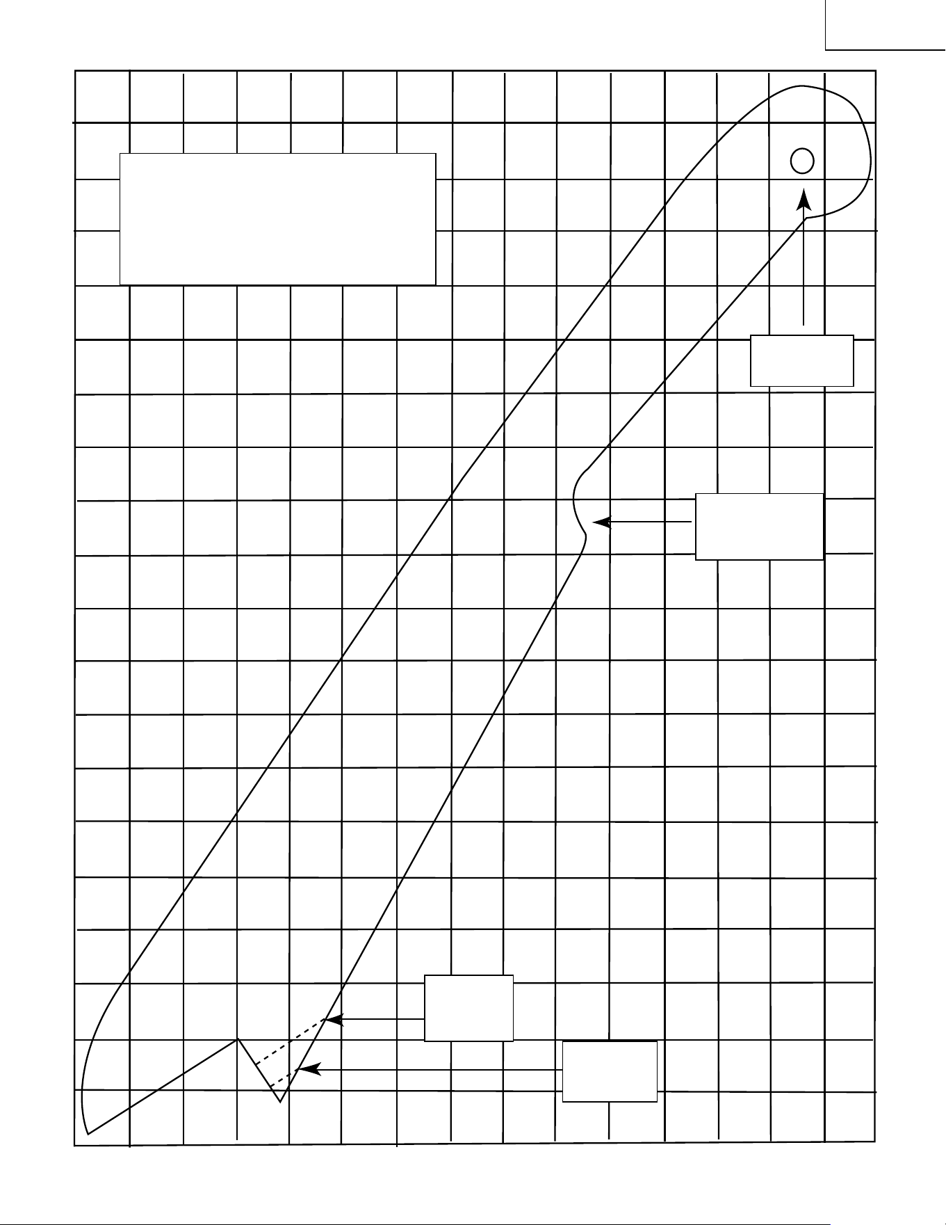
PUSH STICK CONSTRUCTION
●
This is a full-size drawing (actual size)
●
Use good quality plywood or solid wood
●
Use 1/2 in. or 3/4 in. material
●
Push stick MUST be thinner than the width
of material being cut
Drill Hole For
Hanging
Notch To Prevent
Hand From
Slipping
Cut Here To
Push 1/2 in.
Wood
Cut Here To
Push 3/4 in.
Wood

– 24 –
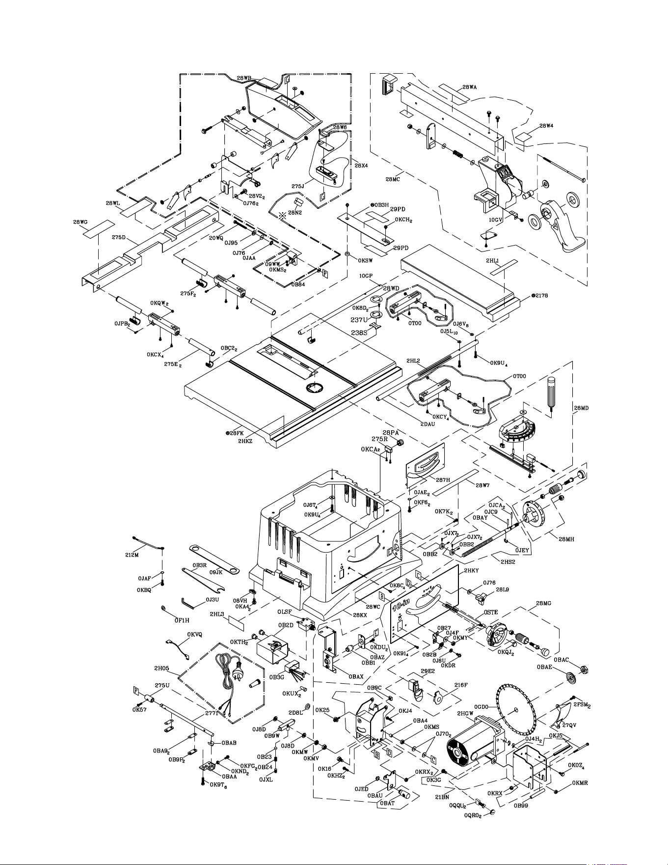
English
Parts No. I.D. Description Size QTY Parts No. I.D. Description Size QTY
726434 08VH CORD CLAMP 1 726587 0KFG CR. RE. PAN HD. SCREW M5*0.8-12 2
726437 09JK WRENCH 1 726588 0KHZ CAP HD. SQ.NECK BOLT M6*1.0-12 2
326604 09WW GUARD BRACKET 1 726589 0KJ4 CAP HD. SQ.NECK BOLT M6*1.0-35 1
726438 0B23 SADDLE 1 726590 0KJ5 CAP HD. SQ.NECK BOLT M6*1.0-80 1
726439 0B24 SPRING 1 726596 0KMR HEX. NUT M5*0.8 T=4 1
726440 0B27 POINTER BRACKET 1 726597 0KMS HEX. NUT M6*1.0 T=5 3
726441 0B2B NEEDLE POINTER 1 726600 0KMV HEX. NUT M10*1.5 T=8 1
326546 0B2D SWITCH BOX 1 726601 0KMW HEX. NUT M10*1.5 T=4 1
326547 0B3G
ELECTROMAGNETIC DISTURBANCE UNITS
1 726603 0KMY HEX. NUT M8*1.25 T=6.5 1
726443 0B3H INSERT 1 726605 0KND HEX. NUT M5*0.8 T=4 2
726444 0B3R WRENCH 1 726612 0KQJ CROWN NUT M8*1.25 T=12.5 2
726445 0B84 WASHER D=φ18 1 726615 0KQW LOCK NUT M5*0.8 T=5 2
726446 0B99 SPACER 1 726622 0KRX HEXAGON NUT AND FLAT WASHER M6*1.0 3
726447 0B9C PLUNGER HOUSING 1 726625 0KSW STRAIN RELIEF 1
726448 0B9P CLAMP 2 326453 0KTH STRAIN RELIEF 2
726449 0B9W BRACKET 1 325733 0KUX TERMINAL 2
726450 0BA4 SPACER 1 326428 0KVQ LEAD WIRE ASS’Y 1
726451 0BA9 SPACER 2 326549 0LSF CIRCUIT BREAKER SWITCH 1
726452 0BAA CLAMP 1 326458 0QQU CARBON BRUSH ASS’Y 2
726453 0BAB SHIM 1 326243 0QR0 BRUSH COVER 2
726454 0BAC SET NUT 1 726642 0STE HEIGHT REGULATING BOLT ASS’Y 1
726455 0BAE ARBOR COLLAR 1 726644 0T00 SLIDING BASE ASS’Y 2
726456 0BAT NUT 1 726649 10GP UPPER TUBE 1
726457 0BAU SUPPORTING PLATE 1 326605 10GV POINTER 1
726458 0BAX STIFFENER 1 726345 2178 EXTENTION WING (RIGHT) 1
726459 0BAY SCREW BAR 1 726657 20WQ HEX. HD. BOLT M6*1.0-50 1
726460 0BAZ BEARING SEAT 1 726628 212M LEAD WIRE ASS’Y 1
726461 0BB1 SHAFT 1 726666 216F SWITCH KEY 1
726462 0BB2 PARRLE RING 2 726668 21BN BRACKET GROUP ASS’Y 1
756463 0BC2 LOCATION SEAT 2 726695 237U COVER 1
326548 0F1H COLLAR 1 726711 238S POINTER 1
762466 0GD0 BLADE 1 726354 2771 ANGLE ROD 1
726476 0J3U HEX WRENCH 1 726759 275D EXTENTION WING 1
726478 0J4F FLAT WASHER φ8*16-2.5 1 726760 275E UPER TUBE 2
726479 0J4H FLAT WASHER φ10*30-0.2 2 726761 275F LOCATION SEAT 2
726483 0J5L FLAT WASHER φ5*10-0.3 10 326606 275J BATTERY BOX ASS’Y 1
726485 0J6T FLAT WASHER 3/16*3/4-1/16 4 726762 275R LOCATION SEAT 1
726486 0J6U FLAT WASHER 3/16*1/2-3/64 1 726763 275U SPACER 1
726487 0J6V FLAT WASHER 3/16*3/8-0.022 8 726778 27QV DEFLECTOR 1
726488 0J70 FLAT WASHER 1/4*3/4-7/64 2 726782 287H RETAINING CLIP 1
726490 0J76 FLAT WASHER 1/4*3/4-1/16 4 726790 28FK TABLE 1
726495 0J8D FLAT WASHER 3/8*3/4-5/64 2 726796 28KX BODY SHELL 1
726497 0J95 SPRING WASHER φ6 1 726799 28L9 LOCK KNOB 1
726500 0JAA WASHER φ8 1 726802 28MC PARALLEL BRACKET ASS’Y 1
726501 0JAE EXTERNAL TOOTH LOCK WASHER φ4 2 726803 28MD MITER GAUGE ASS’Y 1
726502 0JAF EXTERNAL TOOTH LOCK WASHER φ5 1 726804 28MG HANDWHEEL ASS’Y 1
726506 0JC9 SPRING PIN 1 726805 28MH HANDWHEEL ASS’Y 1
726507 0JCA SPRING PIN 2 726322 28N2 BATTERY 1
726513 0JED C-RING 1 726812 28PA KNOB 1
726515 0JEY E-RING 1 326607 28W4 STICKER 1
726523 0JPB HEX. HD. BOLT M5*0.8-20 2 326608 28W6 STICKER 1
726534 0JX7 HEX. SOC. SET SCREW M6*1.0-6 4 326609 28W7 CAUTION LABEL 1
726535 0JXL HEX. SOC. SET SCREW M10*1.5-12 1 326610 28WA CAUTION LABEL 1
726532 0K0Z HEX. HD. SCREW AND WASHER M8*1.25-16 4 326611 28WB WARNING LABEL 1
726534 0K16 HEX. HD. SCREW AND WASHER M8*1.25-16 1 326612 28WC WARNING LABEL 1
726538 0K25 HEX. SOCKET HD. CAP SCREWS M5*0.8-20 1 326613 28WD CAUTION LABEL 1
726543 0K3G CR. RE. PAN HD. SCREW & WASHER M5*0.8-12 1 326614 28WG WARNING LABEL 1
726549 0K57 CR. RE. COUNT HD. SCREW M5*0.8-16 1 326615 28WL WARNING LABEL 1
726557 0K7K CR. RE. ROUND WASHER HD. SCREW M6*1.0-12 2 726861 28X4 BLADE GUARD ASS’Y 1
726561 0K8C CR. RE.COUNT HD. TAPPING SCREW M4*18-10 4 325772 28V2 HEX. WASHER HD. BOLT M6*1.0-16 2
726562 0K8D CR. RE.COUNT HD. TAPPING SCREW M4*18-16 2 726355 29E2 ROCKER SWITCH 1
726563 0K91 CR. RE. TRUSS HD. TAPPING SCREW M4*16-12 4 726290 29PD WARNING LABEL 2
726566 0K9T HEX. HD. TAPPING SCREW M5*16-16 6 326616 2D8L FERRITE CORE 1
726567 0K9U HEX. HD. TAPPING SCREW M5*16-25 8 726291 2DAU UPPER TUBE 1
726570 0KA4 CR. RE. PAN HD. TAPPING SCREW M4*16-16 2 326438 2FSM
CR. RE. PAN HD PLAIN WASHER TAPPING SCREW
M5*0.8-8 2
326437 0KBQ CR. RE. PAN HD. TAPPING SCREW M5*16-10 1 326552 2H05 POWER CABLE ASS’Y 1
726575 0KCA CR. RE. TRUSS HD. TAPPING SCREW M5*12-12 2 326618 2HGW MOTOR 1
726576 0KCH
CR.RE. PAN HEAD TAPPING & WASHER SCREW
M5*0.8-12 2 326619 2HKY RETAINING CLIP 1
726577 0KCX
CR. RE. PAN HD PLAIN WASHER TAPPING SCREW
M5*0.8-10 4 326620 2HKZ SCALE 1
726578 0KCY
CR. RE. PAN HD PLAIN WASHER TAPPING SCREW
M5*0.8-12 4 326621 2HL1 SCALE 1
726581 0KDR CR. RE. PAN HD. SCREW M5*0.8-10 1 326622 2HL2 SCALE 1
726582 0KDU CR. RE. PAN HD. SCREW M6*1.0-12 2 326623 2HL3 LABEL 1
726585 0KF6 CR. RE. PAN HD. SCREW M4*0.7-8 2 326624 2HS2 BEVEL ANGLE ADJUSTMENT ASS’Y 1
PARTS LIST
10” (255mm) JOBSITE TABLE SAW MODEL NO. C10FR
PARTS LIST FOR SCHEMATIC Always order by I.D. Number
– 25 –
English
10” (255mm) JOBSITE TABLE SAW MODEL NO. C10FR
– 26 –
English
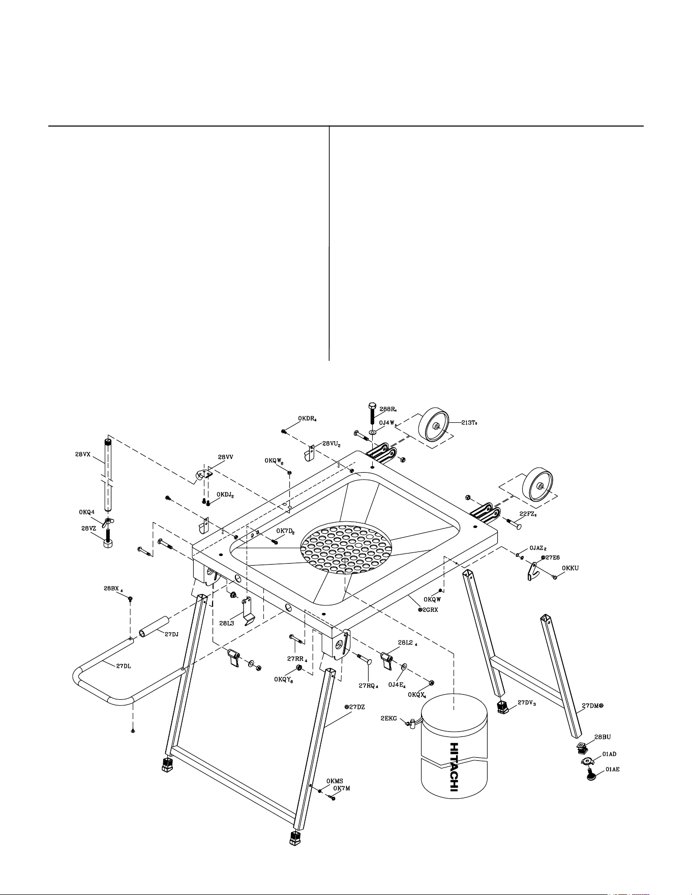
10” (255mm) JOBSITE TABLE SAW MODEL NO. C10FR
PARTS LIST FOR STAND
Parts No. I.D. Description Size QTY Parts No. I.D. Description Size QTY
726357 01AD WING NUT 1 726765 27DL HANDLE 1
726358 01AE LEVELING PAD 1 726766 27DM BRACKET ASS’Y (RIGHT) 1
726477 0J4E FLAT WASHER φ6*13-1 4 726767 27DV LEVELING PAD 3
726482 0J4W FLAT WASHER φ8.2*18-1.5 4 726770 27DZ BRACKET ASS’Y (LEFT) 1
726503 0JAZ WAVE WASHER 2 726356 27E6 HOOK 1
726554 0K7D
CR. RE. ROUND WASHER HD. SCREW
M6*1.0-10 2 726779 27RQ CAP HD. SQ.NECK BOLT M8*1.25-40 4
726559 0K7M
CR. RE. ROUND WASHER HD. SCREW
M6*1.0-18 1 726780 27RR CR. RE. TRUSS HD. SCREW M6*1.0-46 4
726580 0KDJ CR. RE. PAN HD. SCREW M5*0.8-12 2 726783 288R HEX. HD. BOLT M8*1.25-55 4
726581 0KDR CR. RE. PAN HD. SCREW M5*0.8-10 4 726784 28BU FLOOR PLATE 1
726594 0KKU
CR. RE. PAN HD. ROUND NECK SCREW
M5*08-10 1 726785 28BX
CR. RE. PAN HD PLAIN WASHER TAPPING SCREW
M5*0.8-10 4
726597 0KMS HEX. NUT M6*1.0 T=5 1 726797 28L2 CLAMP HANDLE 4
726610 0KQ4 WING NUT M8*1.25 1 726798 28L3 FOLLOWER PLATE 1
726615 0KQW LOCK NUT M5*0.8 T=5 7 726831 28VU HOOK 2
726616 0KQX NUT M6*1.0 T=6 4 726832 28VV CONNECTOR 1
726617 0KQY LOCK NUT M8*1.25 T=8 6 726833 28VX SUPPORTING TUBE ASS’Y 1
726665 213T ROLLING WHEEL 2 726834 28VZ LEVELING PAD 1
726673 22FZ CAP HD. SQ.NECK BOLT M8*1.25-45 2 326617 2GRX DUST COLLECTOR ASS’Y 1
726764 27DJ FOAM 1 726809 2EKG DUST BAG 1

– 27 –
English

– 28 –
English
Issued by
Hitachi Koki Co., Ltd.
Shinagawa Intercity Tower A, 15-1, Konan 2-chome,
Minato-ku, Tokyo 108-6020, Japan
607
Code No. C99135011
Printed in Taiwan