
Vehicle-Mounted Camera
User Manual
UD28551B-A

©2022 Hangzhou Hikvision Digital Technology Co., Ltd. All rights
reserved.
About this Manual
The Manual includes instructions for using and managing the Product.
Pictures, charts, images and all other information hereinafter are for
description and explanation only. The information contained in the
Manual is subject to change, without notice, due to firmware updates
or other reasons. Please find the latest version of this Manual at the
Hikvision website (http://www.hikvision.com/).
Trademarks
•
and other Hikvision's trademarks and logos are the
properties of Hikvision in various jurisdictions.
• Other trademarks and logos mentioned are the properties of their
respective owners.
Disclaimer
TO THE MAXIMUM EXTENT PERMITTED BY APPLICABLE LAW, THIS
MANUAL AND THE PRODUCT DESCRIBED, WITH ITS HARDWARE,
SOFTWARE AND FIRMWARE, ARE PROVIDED “AS IS” AND “WITH ALL
FAULTS AND ERRORS”. HIKVISION MAKES NO WARRANTIES, EXPRESS
OR IMPLIED, INCLUDING WITHOUT LIMITATION, MERCHANTABILITY,
SATISFACTORY QUALITY, OR FITNESS FOR A PARTICULAR PURPOSE.
THE USE OF THE PRODUCT BY YOU IS AT YOUR OWN RISK. IN NO
EVENT WILL HIKVISION BE LIABLE TO YOU FOR ANY SPECIAL,
CONSEQUENTIAL, INCIDENTAL, OR INDIRECT DAMAGES, INCLUDING,
AMONG OTHERS, DAMAGES FOR LOSS OF BUSINESS PROFITS,
BUSINESS INTERRUPTION, OR LOSS OF DATA, CORRUPTION OF
SYSTEMS, OR LOSS OF DOCUMENTATION, WHETHER BASED ON
BREACH OF CONTRACT, TORT (INCLUDING NEGLIGENCE), PRODUCT
LIABILITY, OR OTHERWISE, IN CONNECTION WITH THE USE OF THE
PRODUCT, EVEN IF HIKVISION HAS BEEN ADVISED OF THE POSSIBILITY
OF SUCH DAMAGES OR LOSS. YOU ACKNOWLEDGE THAT THE NATURE
OF INTERNET PROVIDES FOR INHERENT SECURITY RISKS, AND
HIKVISION SHALL NOT TAKE ANY RESPONSIBILITIES FOR ABNORMAL
OPERATION, PRIVACY LEAKAGE OR OTHER DAMAGES RESULTING
FROM CYBER-ATTACK, HACKER ATTACK, VIRUS INSPECTION, OR OTHER
INTERNET SECURITY RISKS; HOWEVER, HIKVISION WILL PROVIDE
TIMELY TECHNICAL SUPPORT IF REQUIRED. YOU AGREE TO USE THIS
PRODUCT IN COMPLIANCE WITH ALL APPLICABLE LAWS, AND YOU
ARE SOLELY RESPONSIBLE FOR ENSURING THAT YOUR USE CONFORMS
TO THE APPLICABLE LAW. ESPECIALLY, YOU ARE RESPONSIBLE, FOR
USING THIS PRODUCT IN A MANNER THAT DOES NOT INFRINGE ON
THE RIGHTS OF THIRD PARTIES, INCLUDING WITHOUT LIMITATION,
RIGHTS OF PUBLICITY, INTELLECTUAL PROPERTY RIGHTS, OR DATA
PROTECTION AND OTHER PRIVACY RIGHTS. YOU SHALL NOT USE THIS
PRODUCT FOR ANY PROHIBITED END-USES, INCLUDING THE
DEVELOPMENT OR PRODUCTION OF WEAPONS OF MASS
DESTRUCTION, THE DEVELOPMENT OR PRODUCTION OF CHEMICAL
OR BIOLOGICAL WEAPONS, ANY ACTIVITIES IN THE CONTEXT RELATED
TO ANY NUCLEAR EXPLOSIVE OR UNSAFE NUCLEAR FUEL-CYCLE, OR IN
SUPPORT OF HUMAN RIGHTS ABUSES. IN THE EVENT OF ANY
CONFLICTS BETWEEN THIS MANUAL AND THE APPLICABLE LAW, THE
LATER PREVAILS.
Regulatory Information
FCC Information
FCC compliance: This equipment has been tested and found to
comply with the limits for a Class B digital device, pursuant to part
15 of the FCC Rules. These limits are designed to provide
reasonable protection against harmful interference when the
equipment is operated in a residential environment. This
equipment generates, uses and can radiate radio frequency energy
and, if not installed and used in accordance with the instructions,
may cause harmful interference to radio communications.
However, there is no guarantee that interference will not occur in
a particular installation. If this equipment does cause harmful
interference to radio or television reception, which can be
determined by turning the equipment off and on, the user is
encouraged to try to correct the interference by one or more of
the following measures:
—Reorient or relocate the receiving antenna.
—Increase the separation between the equipment and receiver.
—Connect the equipment into an outlet on a circuit different from
that to which the receiver is connected.
—Consult the dealer or an experienced radio/TV technician for
help
FCC Conditions
This device complies with part 15 of the FCC Rules. Operation is
subject to the following two conditions:
1. This device may not cause harmful interference.
2. This device must accept any interference received, including
interference that may cause undesired operation
The equipment should be installed and operated with a minimum
distance 20 cm between the radiator and your body.
EU Conformity Statement
This product and - if applicable - the supplied
accessories too are marked with "CE" and comply
therefore with the applicable harmonized European
standards listed under the Low Voltage Directive
2014/35/EC, the EMC Directive 2014/30/EC.
2012/19/EU (WEEE directive): Products marked with
this symbol cannot be disposed of as unsorted
municipal waste in the European Union. For proper
recycling, return this product to your local supplier upon
the purchase of equivalent new equipment, or dispose
of it at designated collection points. For more
information see: www.recyclethis.info.
2006/66/EC (battery directive): This product contains a
battery that cannot be disposed of as unsorted
municipal waste in the European Union. See the
product documentation for specific battery information.
The battery is marked with this symbol, which may
include lettering to indicate cadmium (Cd), lead (Pb), or
mercury (Hg). For proper recycling, return the battery to
your supplier or to a designated collection point. For
more information see: www.recyclethis.info.

The symbols that may be found in this document are defined as
follows.
Description
Provides additional information to
emphasize or supplement important points
of the main text.
Indicates important oprations or potential
hazardous situation that could result in
damage or property loss.
Keep the camera away from liquid while in use.
Do not drop the camera or subject it to physical shock.
Do not touch senor modules with fingers. If cleaning is necessary, use
clean cloth with a bit of ethanol and wipe it gently. If the camera will
not be used for an extended period, replace the lens cap to protect the
sensor from dirt.
To avoid heat accumulation, good ventilation is required for operating
environment.
Do not aim the camera at the sun or extra bright places. Blooming or
smearing may occur otherwise (which is not a malfunction), and
affect the endurance of sensor at the same time.
The sensor may be burned out by a laser beam, so when any laser
equipment is in using, make sure that the surface of sensor will not be
exposed to the laser beam.
Do not place the camera in extremely hot, cold, dusty or damp locations,
and do not expose it to high electromagnetic radiation.
While in delivery, the camera shall be packed in its original packing, or
packing of the same texture.
If the product does not work properly, contact your dealer or the
nearest service center. Never attempt to disassemble the camera by
yourself. (We shall not assume any responsibility for problems caused
by unauthorized repair or maintenance.)
These instructions are intended to ensure that user can use the
product correctly to avoid danger or property loss. Before using,
please read the manual carefully and keep it properly for further
reference.
Indicates a hazard with a high level of risk,
which if not avoided, will result in death or
serious injury.
Indicates a potentially hazardous situation,
which if not avoided, could result in
equipment damage, data loss, performance
degradation, or unexpected results.
In the use of the product, you must be in strict compliance with the
electrical safety regulations of the nation and region. Input voltage should
meet both the SELV (Safety Extra Low Voltage) and the Limited Power
Source with AC 24V or DC 12V according to the IEC60950-1 standard.
Refer to technical specifications for detailed information.
Foreword
Symbol Conventions
Symbol
NOTE
CAUTION
WARNING
DANGER
Safety Instruction
3
Table 1-1 Packing List
2.1 Key Features
This series of camera adopts new generation sensor with high
sensitivity and advanced circuit design technology. It features
high resolution, low image distortion and low noise, etc.,
making it suitable for monitoring system and image processing
system.
The main features are as follows:
2 Introduction
Progressive Scan CMOS for accurate capture of moving subjects
High quality images
Low illumination of 0.01 Lux@(F1.2 AGC On), 0 Lux with IR
Supports automatic switch from colorful to black and white
Supports two-way lens for more monitor content
Supports auto electronic shutter
Supports auto gain control
1 Package Check
1.1 Before You Begin
Before unboxing, please check if the package is intact.
Unbox and check the list to make sure that all the assembly
parts are included.
If there is no problem, the device is ready for installation.
1.2 Packing List
The packing list of the camera is shown below.
The assembly parts may vary according to different camera models.
Refer to the actual device for details.
NOTE
4
No. Picture for Illustration
Name
Number
1
2
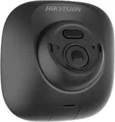
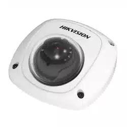
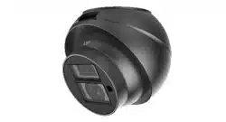
Front Camera
Back Camera
1
1
3
Screw Bag
4
5
Sta�c
1
Manual
1
1
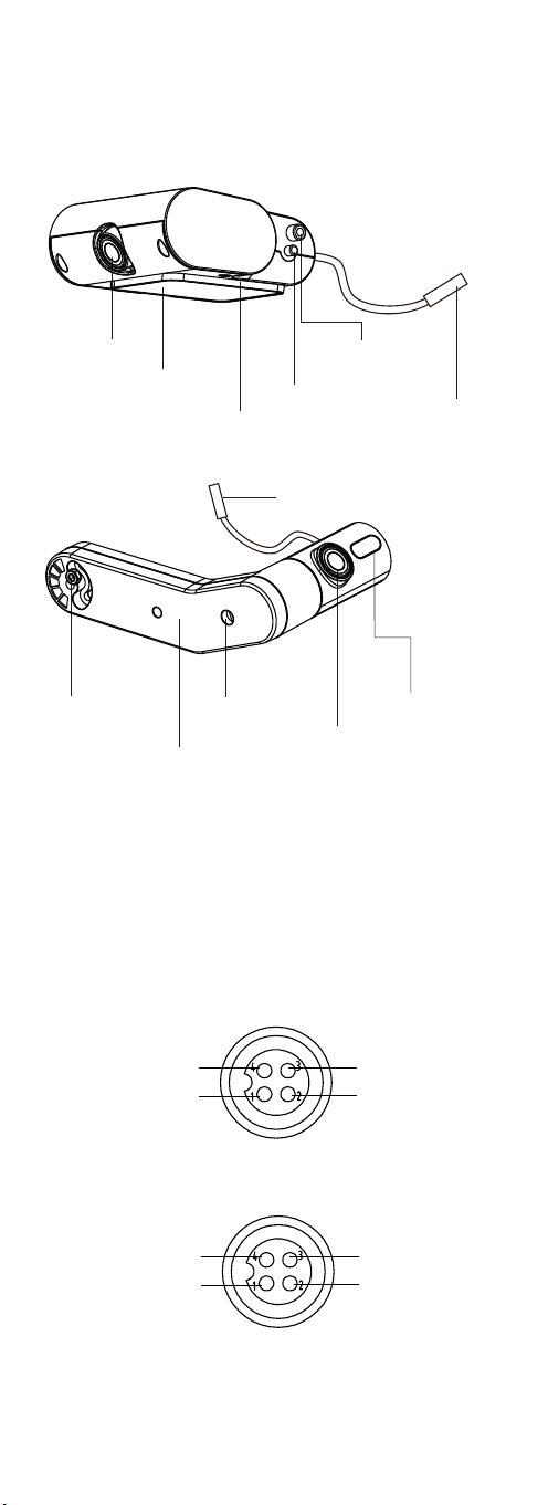
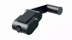
Figure 2-1 Overview
Figure 2-3 Interfaces of Aviation Plug
Figure 2-2 Interfaces of Aviation Plug
Video
Power Ground
Power Supply
Video
Power Ground
NC
NC
Power Supply
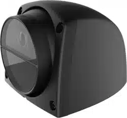
2.2 Structure and Components
2.2.1 Overview
Front Camera
Guide Post
Rota�on Sha�
Double-Sided Tape
Moun�ng Bracket
Avia�on Plug
Back Camera
Avia�on Plug
Infra-Red Indicator
Screw Hole 1
Screw Hole 2
Connecting Rod
2.2.2 Aviation Plug Cable
The power supply for the camera is 9 V to 16 V wide voltage range
mobile DC. The camera adopts aviation plugs, as shown in Figure 2-2.
There are two types of pin assignments, as shown in Figure 2-2 and
2-30 Make sure that your cable matches with the plug.
5
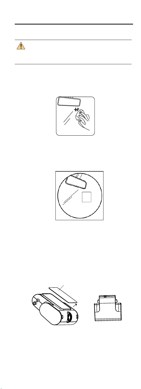
Figure 3-1 Clean the Surface
Figure 3-2 Tag the Electrostatic Film
3 Installation
Before you begin, make sure that the device in the package
is in good condition and all the assembly parts are included.
Make sure the mounting part for camera installation is strong
enough to hold four times of the weight of the camera and its
mounting parts. Choose an even surface for installation.
Tag the electrostatic film on the cleaned mounting
position.
CAUTION
Step 2
Step 3
Step 4
Clean the mounting surface with a mixture of isopropyl
and water.
Step 1 Choose a mounting position according to the visual
condition.
6
Double-Sided Release Paper
Figure 3-3 Mount Front Camera
Tear off the double-sided tape release sticker to the
device and stick the front camera to the lectrostatic film.
7
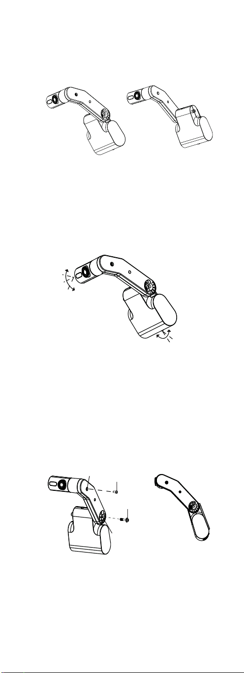
20°
20°
15°
15°
Figure 3-4 Mount Back Camera
Figure 3-5 Mount Back-Camera
Figure 3-6 Fix the Camera
Screw 1
Screw Hole 1
Screw Hole 2
Screw 2
Step 6
Step 7
Fix the camera. A�er adjus�ng the camera to a
proper angle, place the screw 1 into screw hole 1 to
connect the front camera to the connec�ng rod, and
place the screw 2 into the screw hole 2 to connect the
back camera to the connec�ng rod.
Connect cable and adjust the camera to a proper
angle according to the camera vision. The angle of
the front and back camera are adjustable, as shown
in Figure 3-5.
Step 5 Mount the back camera. The back camera can be
mounted on the le� or right side of front camera
according to the mobile se�ng, as shown in Figure
3-4.