
TURBO HD TVI Dome Camera
User Manual
UD02995B-A

1
UserManual
Thank you for purchasing our product. If there are any
questions, or requests, do not hesitate to contact the
dealer.
This manual applies to Vehicle-Mounted Camera.
This manual may contain several technically incorrect
places or printing errors. The content is subject to change
without notice, and the updates will be added to the new
version of this manual. We will readily improve or update
the products or procedures described in the manual.
RegulatoryInformation
FCCInformation
FCCcompliance:Thisequipment has been tested and
found to comply with the limits for a digital device,
pursuant to part 15 of the FCC Rules. These limits are
designed to provide reasonable protection against
harmful interference when the equipment is operated in
a commercial environment. This equipment generates,
uses, and can radiate radio frequency energy and, if not
installed and used in accordance with the instruction
manual, may cause harmful interference to radio
communications. Operation of this equipment in a
residential area is likely to cause harmful interference in
which case the user will be required to correct the
interference at his own expense.
FCCConditions
This device complies with part 15 of the FCCRules.
Operation is subject to the following two conditions:
1. This device may not cause harmful interference.
2. This device must accept any interference received,
including interference that may cause undesired
operation
EUConformity Statement
This product and - if applicable - the
supplied accessories too are marked with
"CE" and comply therefore with the
applicable harmonized European standards listed under
the Low Voltage Directive 2014/35/EC, the EMC Directive
2014/30/EC.
2012/19/EU (WEEE directive): Products
marked with this symbol cannot be
disposed of as unsorted municipal waste in
the European Union. For proper recycling,
return this product to your local supplier
upon the purchase of equivalent new equipment, or
dispose of it at designated collection points. For more
information see: www.recyclethis.info.
2006/66/EC (battery directive): This
product contains a battery that cannot be

2
disposed of as unsorted municipal waste in the European
Union. See the product documentation for specific
battery information. The battery is marked with this
symbol, which may include lettering to indicate cadmium
(Cd), lead (Pb), or mercury (Hg). For proper recycling,
return the battery to your supplier or to a designated
collection point. For more information see:
www.recyclethis.info.
Industry CanadaICES-003Compliance
This device meets the CAN ICES-3 (A)/NMB-3(A)
standards requirements.
Safety Instruction
These instructions are intended to ensure that user can
use the product correctly to avoid danger or property
loss.
The precaution measure is divided into “Warnings” and
“Cautions”
Warnings:Seriousinjury or death may occur if any of the
warnings are neglected.
Cautions:Injuryor equipment damage may occur if any
of the cautions are neglected.
Warnings
In the use of the product, you must be in strict
compliance with the electrical safety regulations of
the nation and region. Refer to technical specifications
for detailed information.
Input voltage should meet both the SELV (Safety Extra
Low Voltage) and the Limited Power Source with AC
24V or DC 12V according to the IEC60950-1 standard.
Refer to technical specifications for detailed
information.
Do not connect several devices to one power adapter
as adapter overload may cause over-heating or a fire
hazard.
Make sure that the plug is firmly connected to the
power socket.
When the product is mounted on wall or ceiling, the
device shall be firmly fixed.
WarningsFollow
these safeguards to
prevent serious injury
or death.
CautionsFollow these
precautions to prevent
potential injury or
material damage.
3
If smoke, odor or noise rise from the device, turn off
the power at once and unplug the power cable, and
then please contact the service center.
If the product does not work properly, contact your
dealer or the nearest service center. Never attempt to
disassemble the camera by yourself. (We shall not
assume any responsibility for problems caused by
unauthorized repair or maintenance.)
Cautions
Make sure the power supply voltage is correct before
using the camera.
Do not drop the camera or subject it to physical shock.
Do not touch senor modules with fingers. If cleaning is
necessary, use clean cloth with a bit of ethanol and
wipe it gently. If the camera will not be used for an
extended period, replace the lens cap to protect the
sensor from dirt.
Do not aim the camera at the sun or extra bright
places. Blooming or smearing may occur otherwise
(which is not a malfunction), and affect the endurance
of sensor at the same time.
The sensor may be burned out by a laser beam, so
when any laser equipment is in using, make sure that
the surface of sensor will not be exposed to the laser
beam.
Do not place the camera in extremely hot, cold, dusty
or damp locations, and do not expose it to high
electromagnetic radiation.
To avoid heat accumulation, good ventilation is
required for operating environment.
Keep the camera away from liquid while in use.
While in delivery, the camera shall be packed in its
original packing, or packing of the same texture.
SymbolConventions
The symbols that may be found in this document are
defined as follows.
Symbol Description
Provides additional information to
emphasize or supplement important
points of the main text.
Indicates a potentially hazardous
situation, which if not avoided, could
result in equipment damage, data loss,
performance degradation,o r
unexpected results.
Indicates a hazard with a high level of risk,
which if not avoided, will result in death or
serious injury.
4
1 Introduction
1.1 Product Features
This series of camera adopts high performance CMOS
sensor and advanced circuit board. It features high
resolution, low distortion, and low noise, etc. It is suitable
for monitoring system, and image process system.
The main features are as follows:
High performance CMOS sensor
1080p resolution
Auto white balance
Auto electronic shutter
Auto gain control (AGC)
True WDR
IR cut filter
Internal 3-axis adjustment
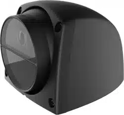
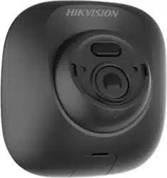
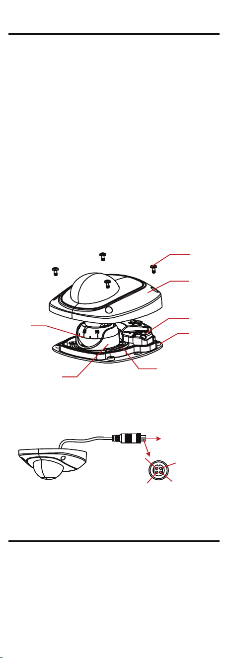
1.2 Overview
The overview of dome camera is shown below.
Camera
MountingBase
Menu Button
Upper Cover
Torx Screw
Enclosure
AdjustableS crew
Figure 1-1 Overview of Dome Camera
1.3 Interface of Aviation Plug
The interface of aviation plug is shown below.
1
2
3
4
Video
Audio
Power (12V DC)
GND
Aviation Plug
Interface of Aviation PlugFigure 1-2
2 Installation
Before youstart:
Make sure that the device in the package is in good
condition and all the assembly parts are included.
Make sure that all the related equipment is power-off
during the installation.
5
Check the specification of the products for the
installation environment.
Check whether the power supply is matched with your
power output to avoid damage.
Make sure the wall is strong enough to withstand four
times the weight of the camera and the mounting
bracket.
If the wall is cement l, you need to insert expansion
bolts before you install the camera. If the wall is
wooden, you can use self-tapping screws to secure the
camera.
If the product does not function properly, contact your
dealer or the nearest service center. Do NOT
disassemble the camera for repair or maintenance by
yourself.
2.1 Ceiling Mounting
The dome camera supports ceiling mounting. The
installation steps are shown as follows.
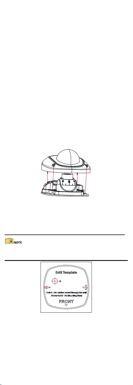
Step 1 Loosen the torx screws to remove the upper
cover from the device.
Figure 2-1 Remove the Upper Cover
Step 2 Stick the dill template to the ceiling. Step
3 Drill the screw holes, and the cable hole
(optional) in the ceiling according to the drill
template.
Cable hole is required when you adopts ceiling outlet to
route the cable.
Figure 2-2 Drill Template
Step 4 Fix the mounting base to the ceiling with the
supplied screws.
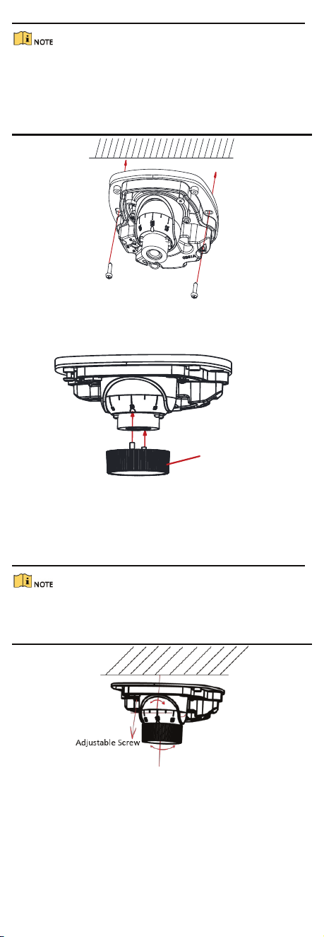
6
In the supplied screw package, both self-tapping
screws and expansion blots are contained.
If the wall is cement, expansion blots are required to
fix the camera. If the wall is wooden, self-tapping
screws are required.
Figure 2-3 Fix the Mounting Base
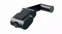
Step 5 Align the supplied adjusting tool to the small
hole on the camera, and push it to get it fixed.
Adjusting Tool
Figure 2-4 Align the Adjusting Tool
Step 6 Loosen the adjustable screw to adjust the pan
angle (±30°), the tilting angle (0° to 75°), and the
rotation angle (±180°) with the adjusting tool,
then tighten the adjustable screws.
Before adjusting the surveillance angle, you need to
power on the camera first to check whether the image on
the monitor is gotten from the optimum angle.
Figure 2-5 3-axis Adjustment
Step 7 Install the upper cover back by tightening the
torx screws.
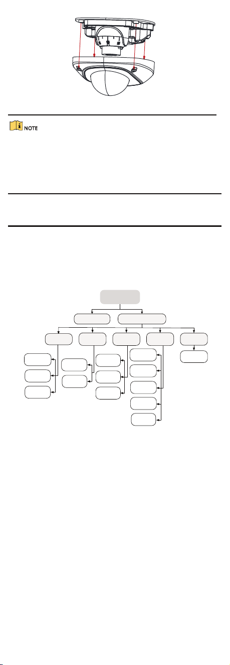
7
Install the Upper CoverFigure 2-6
The camera is in optimum surveillance angle by
default. Slightly adjust the pan tilting angle according
to the actual environment.
The upper cover should be installed before having the
live view.
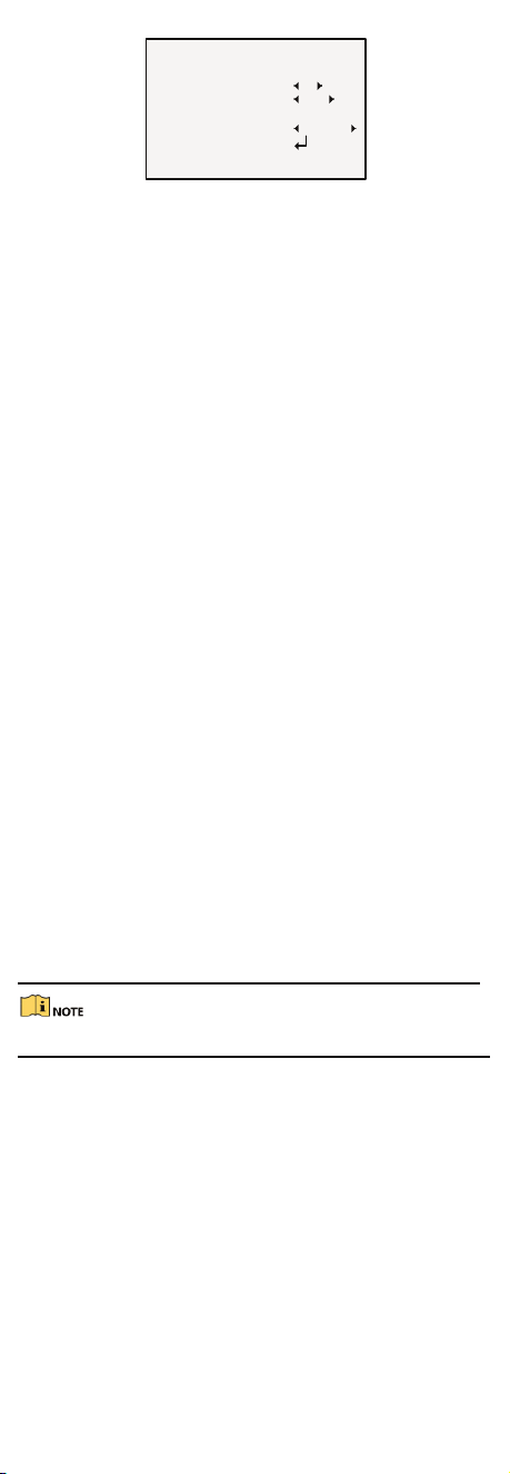
3 Menu Description
Loosen the torx screws via L type wrench and hold the
menu button for 2 seconds. The OSD menu will be
displayed on the display device.
You can use the menu button to move the cursor up,
down, left or right to set the parameters for the camera.
MAIN MENU
AE WB
DAY
&NIGHT
VIDEO
SETTING
RESET
SAVE
&EXIT
BRIGHTNESS
EXPOSURE
MODE
GAIN
ATW
MWB
COLOR
B/W
CONTRAST
SHARPNESS
COLOR
GAIN
DNR
MIRROR
SMART
FORMAT
SETUP
Figure 3-1 Main Menu Overview
3.1 Format
Move the cursor to FORMAT,andconfirm to enter the
FORMAT sub menu. You can set the format as NTSC or
PAL.
3.2 Main Menu
3.2.1 AE (Auto Exposure)
AE describes the brightness-related parameters. You can
adjust the image brightness by the BRIGHTNESS,
EXPOSUREMODE,andGAINindifferent light conditions.
8
EXPO SURE
BRIGHTNESS
EXPO SURE
MO DEGAIN
RETURN
5
BLC
MIDDLE
AE
Figure 3-2
BRIGHTNESS
Brightness refers to the brightness of the image. You can
set the brightness value from 1 to 10 to darken or
brighten the image. The higher the value, the brighter the
image is.
EXPOSURE MODE
You canset AEmode as GLOBAL,BLC,andWDR.
GLOBAL
GLOBAL refers to the normal exposure mode which
adjusts the situations including unusual lighting
distribution, variations, non-standard processing, or
under other exposure conditions to get an optimum
image.
BLC (Backlight Compensation)
BLC (Backlight Compensation) compensates light to the
object in the front to make it clear, but this causes the
over-exposure of the background where the light is
strong.
When BLC is selected as the exposure mode, the BLC level
can be adjusted from 0 to 8.
WDR (Wide Dynamic Range)
The wide dynamic range helps the camera provide clear
images even under backlight circumstances. WDR
balances the brightness level of the whole image and
provides clear images with details.
GAIN
It optimizes the clarity of the image in poor light
conditions. The GAINlevel can be set as HIGH,MIDDLE,
or LOW.Select OFFto disable the GAINfunction.
The noise will be amplified when the GAIN is on.
3.2.2 WB (White Balance)
White balance, the white rendition function of the
camera, is to adjust the color temperature according to
the environment. It can remove unrealistic color casts in
the image. You can set WB mode as ATW,or MWB.
ATW
Under ATWmode, white balance is being adjusted
automatically according to the color temperature of the
scene illumination.

9
MWB
You can set the RGAIN/BGAINvalue from 0 to 255 to
adjust the shades of red/blue color of the image.
WB
MODE
R GAIN
B GAIN
RETURN
MWB
5
5
Figure 3-3 MWB Mode
3.2.3 DAY-NIGHT
Color, B/W, and SMART are selectable for DAY and NIGHT
switches.
COLOR
The image is colored in day mode all the time.
B/W
The image is black and white all the time, and the IR LED
turns on in the low-light conditions.
SMART
You can turn on/off the INFRAREDandsetthe value of
SMARTIRin this menu.
DAY/NIGHT
MODE
INFRARED
SMART IR
DAY TO NIGHT
NIGHT TO DAY
RETURN
SMART
OPEN
1
6 6
Day & Night
Figure 3-4
INFRARED
You can turn on/off the IR LED to meet the
requirements of different circumstances.
SMART IR
The SmartIRfunction is used to adjust the light to its
most suitable intensity, and to prevent the image from
over exposure. The SMARTIRvalue can be adjusted
from 0 to 3. The higher the value the more obvious
effects are, and it is disabled when the value is 0.
DAY TO NIGHT
Set the value from 1 to 10. The higher the value, the
easier the color status switches to B/W status.
NIGHT TO DAY
Set the value from 1 to 10. The smaller the value, the
easier the B/W status switches to color status.
3.2.4 VIDEO SETTING
Move the cursor to VIDEOSETTINGandconfirm to enter
the submenu. CONTRAST,SHARPNESS,COLORGAIN,
DNR,and MIRRORare adjustable.

10
VIDEO SET TING
CONTRAST
SHARPNESS
COLOR GAIN
DNR
MIRROR
RETURN
5
5
5
5
DEFAULT
Video SettingFigure 3-5
CONTRAST
This feature enhances the difference in color and light
between parts of an image. You can set the CONTRAST
value from 1 to 10.
SHARPNESS
Sharpness determines the amount of detail an imaging
system can reproduce. You can set the SHARPNESSvalue
from 1 to 10.
COLOR GAIN
Adjust this feature to change the saturation of the color.
The value ranges from 1 to 10.
DNR (Digital Noise Reduction)
The DNR function can decrease the noise effect,
especially when capturing moving images in low light
conditions and delivering more accurate and sharp image
quality. You can set the DNRvalue from 1 to 10.
MIRROR
DEFAULT,H,V,and HVare selectable for mirror.
DEFAULT:Themirror function is disabled.
H: The image flips 180° horizontally.
V: The image flips 180° vertically.
HV:The image flips 180° both horizontally and vertically.
3.2.5 RESET
Reset all the settings to the default.
3.2.6 SAVE & EXIT
Move the cursor to SAVE&EXITand confirm to save the
setting and exit the menu.