
Vehicle-Mounted Camera
User Manual
UD09114B-A

1
UserManual
©2018 Hangzhou Hikvision Digital Technology Co., Ltd.
AboutthisManual
This manual applies to Vehicle-Mounted Camera.
This Manual is subject to domestic and international
copyright protection. Hangzhou Hikvision Digital
Technology Co., Ltd. (“Hikvision”) reserves all rights to
this manual. This manual cannot be reproduced, changed,
translated, or distributed, partially or wholly, by any
means, without the prior written permission of Hikvision.
Trademarks
and other Hikvision marks are the
property of Hikvision and are registered trademarks or
the subject of applications for the same by Hikvision
and/or its affiliates. Other trademarks mentioned in this
manual are the properties of their respective owners. No
right of license is given to use such trademarks without
express permission.
Disclaimer
TO THE MAXIMUM EXTENT PERMITTED BY APPLICABLE
LAW, HIKVISION MAKES NO WARRANTIES, EXPRESS OR
IMPLIED, INCLUDING WITHOUT LIMITATION THE IMPLIED
WARRANTIES OF MERCHANTABILITY AND FITNESS FOR A
PARTICULAR PURPOSE, REGARDING THIS MANUAL.
HIKVISION DOES NOT WARRANT, GUARANTEE, OR MAKE
ANY REPRESENTATIONS REGARDING THE USE OF THE
MANUAL, OR THE CORRECTNESS, ACCURACY, OR
RELIABILITY OF INFORMATION CONTAINED HEREIN. YOUR
USE OF THIS MANUAL AND ANY RELIANCE ON THIS
MANUAL SHALL BE WHOLLY AT YOUR OWN RISK AND
RESPONSIBILITY.
TO THE MAXIMUM EXTENT PERMITTED BY APPLICABLE
LAW, IN NO EVENT WILL HIKVISION, ITS DIRECTORS,
OFFICERS, EMPLOYEES, OR AGENTS BE LIABLE TO YOU
FOR ANY SPECIAL, CONSEQUENTIAL, INCIDENTAL, OR
INDIRECT DAMAGES, INCLUDING, AMONG OTHERS,
DAMAGES FOR LOSS OF BUSINESS PROFITS, BUSINESS
INTERRUPTION, SECURITY BREACHES, OR LOSS OF DATA
OR DOCUMENTATION, IN CONNECTION WITH THE USE OF
OR RELIANCE ON THIS MANUAL, EVEN IF HIKVISION HAS
BEEN ADVISED OF THE POSSIBILITY OF SUCH DAMAGES.
SOME JURISDICTIONS DO NOT ALLOW THE EXCLUSION OR
LIMITATION OF LIABILITY OR CERTAIN DAMAGES, SO
SOME OR ALL OF THE ABOVE EXCLUSIONS OR
LIMITATIONS MAY NOT APPLY TO YOU.

2
RegulatoryInformation
FCCInformation
FCCcompliance:Thisequipment has been tested and
found to comply with the limits for a digital device,
pursuant to part 15 of the FCC Rules. These limits are
designed to provide reasonable protection against
harmful interference when the equipment is operated in
a commercial environment. This equipment generates,
uses, and can radiate radio frequency energy and, if not
installed and used in accordance with the instruction
manual, may cause harmful interference to radio
communications. Operation of this equipment in a
residential area is likely to cause harmful interference in
which case the user will be required to correct the
interference at his own expense.
FCCConditions
This device complies with part 15 of the FCC Rules.
Operation is subject to the following two conditions:
1. This device may not cause harmful interference.
2. This device must accept any interference received,
including interference that may cause undesired
operation
EUConformity Statement
This product and - if applicable - the
supplied accessories too are marked with
"CE" and comply therefore with the
applicable harmonized European standards listed under
the Low Voltage Directive 2014/35/EC, the EMC Directive
2014/30/EC.
2012/19/EU (WEEE directive): Products
marked with this symbol cannot be
disposed of as unsorted municipal waste in
the European Union. For proper recycling,
return this product to your local supplier
upon the purchase of equivalent new equipment, or
dispose of it at designated collection points. For more
information see: www.recyclethis.info.
2006/66/EC (battery directive): This
product contains a battery that cannot be
disposed of as unsorted municipal waste in
the European Union. See the product
documentation for specific battery information. The
battery is marked with this symbol, which may include
lettering to indicate cadmium (Cd), lead (Pb), or mercury
(Hg). For proper recycling, return the battery to your
supplier or to a designated collection point. For more
information see: www.recyclethis.info.
Industry Canada ICES-003Compliance
This device meets the CAN ICES-3 (A)/NMB-3(A)
standards requirements.

3
Safety Instruction
These instructions are intended to ensure that user can
use the product correctly to avoid danger or property
loss.
The precaution measure is divided into “Warnings” and
“Cautions”
Warnings:Seriousinjury or death may occur if any of the
warnings are neglected.
Cautions:Injuryor equipment damage may occur if any
of the cautions are neglected.
● In the use of the product, you must be in strict
compliance with the electrical safety regulations of
the nation and region.
● Refer to technical specifications for detailed
information.
● Input voltage should meet both the SELV (Safety Extra
Low Voltage) and the Limited Power Source with AC
24V or DC 12V according to the IEC60950-1 standard.
Refer to technical specifications for detailed
information.
● Do not connect several devices to one power adapter
as adapter overload may cause over-heating or a fire
hazard.
● Make sure that the plug is firmly connected to the
power socket.
● When the product is mounted on wall or ceiling, the
device shall be firmly fixed.
● If smoke, odor or noise rise from the device, turn off
the power at once and unplug the power cable, and
then please contact the service center.
● If the product does not work properly, contact your
dealer or the nearest service center. Never attempt to
disassemble the camera by yourself. (We shall not
assume any responsibility for problems caused by
unauthorized repair or maintenance.)
● Make sure the power supply voltage is correct before
using the camera.
● Do not drop the camera or subject it to physical shock.
● Do not touch senor modules with fingers. If cleaning is
necessary, use clean cloth with a bit of ethanol and
wipe it gently. If the camera will not be used for an
extended period, replace the lens cap to protect the
sensor from dirt.
● Do not aim the camera at the sun or extra bright
places. Blooming or smearing may occur otherwise
(which is not a malfunction), and affect the endurance
of sensor at the same time.

4
● The sensor may be burned out by a laser beam, so
when any laser equipment is in using, make sure that
the surface of sensor will not be exposed to the laser
beam.
● Do not place the camera in extremely hot, cold, dusty
or damp locations, and do not expose it to high
electromagnetic radiation.
● To avoid heat accumulation, good ventilation is
required for operating environment.
● Keep the camera away from liquid while in use.
● While in delivery, the camera shall be packed in its
original packing, or packing of the same texture.
SymbolConventions
The symbols that may be found in this document are
defined as follows.
Symbol Description
Provides additional information to
emphasize or supplement important
points of the main text.
Indicates a potentially hazardous
situation, which if not avoided, could
result in equipment damage, data loss,
performance degradation, or
unexpected results.
Indicates a hazard with a high level of
risk, which if not avoided, will result in
death or serious injury.
5
Introduction
1.1 Product Features
This series of camera adopts new generation sensor with
high sensitivity and advanced circuit design technology. It
features high resolution, low image distortion and low
noise, etc., which makes it suitable for surveillance system
and image processing system.
The main features are as follows:
● High performance CMOS sensor and high resolution
bring high-quality image.
● AGC (Auto Gain Control).
● Aviation plug output, shock proof.
● IP68.
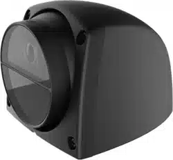
1.2 Overview
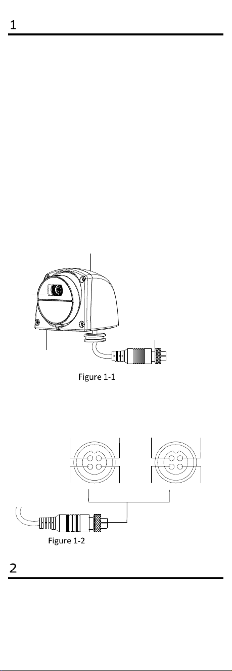
1.2.1 Overview of Vehicle-Mounted Camera
The overview of the camera is shown below.
4-Pin Aviation Plug
Lens
Bracket
Cover
Overview
1.2.2 Aviation Plug Interfaces
There are 2 types for the aviation plug interfaces, as
shown in below.
Video Interface
GND Power Supply
GND
Video Interface
GND
Power Supply
GND
Type A
Type B
Interfaces of Aviation Plug
Installation
Beforeyou start:
6
● Please make sure that the device in the package is in
good condition and all the assembly parts are
included.
● Make sure that all the related equipment is power-off
during the installation.
● Check the specification of the products for the
installation environment.
● Check whether the power supply is matched with your
power output to avoid damage.
● Be sure that there is enough space to install the
camera and accessories.
● Make sure the part, which is used to install the camera,
is strong enough to withstand four times the weight of
the camera and the mounting.
● If the product does not function properly, please
contact your dealer or the nearest service center. Do
not disassemble the camera for repair or maintenance
by yourself.
● Do not pull and drag the camera cables hard.
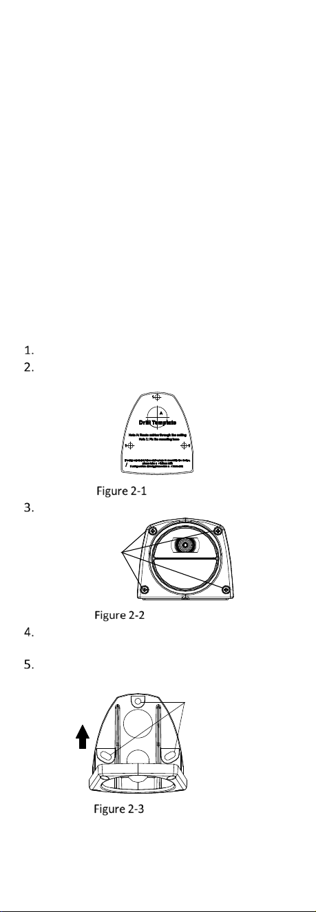
Steps:
Paste the drill template to the vehicle wall.
Drill the screw holes according to the drill
template.
Drill Template
Loosen 4 crews (M2.5 x 7) on the cover.
Set Screws
M 2.5 × 7
Loosen Screws
Align the holes on the bracket with the installation
holes on the drill template.
Use 3 crews (PA4 x 25) to secure the bracket to the
template.
Holes for Fixing
Bracket
Secure Bracket
7
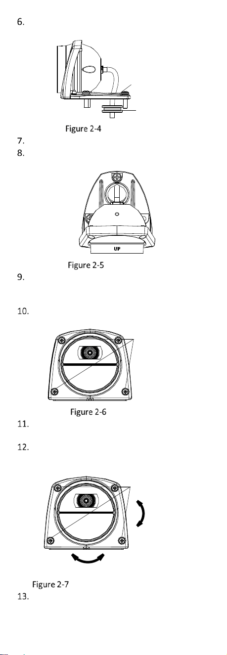
Route camera’s cables through the cable hole of
the bracket.
Seal Ring
Fixing Hole
Route the Cable
Secure the seal ring near the cable hole.
Adjust the camera main body with UP upward as
the figure below.
Adjust Camera
(Optional) If the installation site of the camera
needs to be sealed, please wipe silica gel on the screw
position and the cable hole, and seal them.
Align the cover with the crew holes on the bracket,
and insert 4 set crews (M2.5 x 7).
4 M2.5 x 7 Srews
Insert Screws
Connect the camera’s cables to the corresponding
4-pin aviation plug.
Adjust the camera according to the figure below to
get an optimum angle, and fasten 4 set crews (M2.5 x
7).
Tighten Screws
Pan
-8° to 16°
Tilt:-8° to 8°
Tighten Screws and Adjust Camera
Tear the protective film on the lens off.
