
Vehicle-Mounted Camera
User Manual
UD02784B-A
1
UserManual
Thank you for purchasing our product. If there are any
ques�ons, or requests, do not hesitate to contact the
dealer.
This manual applies to Vehicle-Mounted Camera.
This manual may contain several technically incorrect
places or prin�ng errors. The content is subject to change
without no�ce, and the updates will be added to the new
version of this manual. We will readily improve or update
the products or procedures described in the manual.
RegulatoryInformation
FCCInformation
FCCcompliance:Thisequipment has been tested and
found to comply with the limits for a digital device,
pursuant to part 15 of the FCC Rules. These limits are
designed to provide reasonable protec�on against
harmful interference when the equipment is operated in
a commercial environment. This equipment generates,
uses, and can radiate radio frequency energy and, if not
installed and used in accordance with the instruc�on
manual, may cause harmful interference to radio
communica�ons. Opera�on of this equipment in a
residen�al area is likely to cause harmful interference in
which case the user will be required to correct the
interference at his own expense.
FCCConditions
This device complies with part 15 of the FCCRules.
Opera�on is subject to the following two condi�ons:
1. This device may not cause harmful interference.
2. This device must accept any interference received,
including interference that may cause undesired
opera�on
EUConformity Statement
This product and - if applicable - the
supplied accessories too are marked with
"CE" and comply therefore with the
applicable harmonized European standards listed under
the Low Voltage Direc�ve 2014/35/EC, the EMC Direc�ve
2014/30/EC.
2012/19/EU (WEEE direc�ve): Products
marked with this symbol cannot be
disposed of as unsorted municipal waste in
the European Union. For proper recycling,
return this product to your local supplier
upon the purchase of equivalent new equipment, or
dispose of it at designated collec�on points. For more
informa�on see: www.recyclethis.info.
2006/66/EC (ba�ery direc�ve): This
product contains a ba�ery that cannot be

2
disposed of as unsorted municipal waste in the European
Union. See the product documenta�on for specic
ba�ery informa�on. The ba�ery is marked with this
symbol, which may include le�ering to indicate cadmium
(Cd), lead (Pb), or mercury (Hg). For proper recycling,
return the ba�ery to your supplier or to a designated
collec�on point. For more informa�on see:
www.recyclethis.info.
Industry Canada ICES-003Compliance
This device meets the CAN ICES-3 (A)/NMB-3(A)
standards requirements.
Safety Instruction
These instruc�ons are intended to ensure that user can
use the product correctly to avoid danger or property
loss.
The precau�on measure is divided into “Warnings” and
“Cau�ons”
Warnings:Seriousinjury or death may occur if any of the
warnings are neglected.
Cautions:Injuryor equipment damage may occur if any of
the cau�ons are neglected.
Warnings
In the use of the product, you must be in strict
compliance with the electrical safety regula�ons of
the na�on and region.
Refer to technical specica�ons for detailed
informa�on.
Input voltage should meet both the SELV (Safety Extra
Low Voltage) and the Limited Power Source with AC
24V or DC 12V according to the IEC60950-1 standard.
Refer to technical specica�ons for detailed
informa�on.
Do not connect several devices to one power adapter
as adapter overload may cause over-hea�ng or a re
hazard.
Make sure that the plug is rmly connected to the
power socket.
When the product is mounted on wall or ceiling, the
device shall be rmly xed.
WarningsFollow
these safeguards to
prevent serious injury
or death.
CautionsFollow these
precau�ons to prevent
poten�al injury or
material damage.
3
If smoke, odor or noise rise from the device, turn o
the power at once and unplug the power cable, and
then please contact the service center.
If the product does not work properly, contact your
dealer or the nearest service center. Never a�empt to
disassemble the camera by yourself. (We shall not
assume any responsibility for problems caused by
unauthorized repair or maintenance.)
Cautions
Make sure the power supply voltage is correct before
using the camera.
Do not drop the camera or subject it to physical shock.
Do not touch senor modules with ngers. If cleaning is
necessary, use clean cloth with a bit of ethanol and
wipe it gently. If the camera will not be used for an
extended period, replace the lens cap to protect the
sensor from dirt.
Do not aim the camera at the sun or extra bright
places. Blooming or smearing may occur otherwise
(which is not a malfunc�on), and aect the endurance
of sensor at the same �me.
The sensor may be burned out by a laser beam, so
when any laser equipment is in using, make sure that
the surface of sensor will not be exposed to the laser
beam.
Do not place the camera in extremely hot, cold, dusty
or damp loca�ons, and do not expose it to high
electromagne�c radia�on.
To avoid heat accumula�on, good ven�la�on is
required for opera�ng environment.
Keep the camera away from liquid while in use.
While in delivery, the camera shall be packed in its
original packing, or packing of the same texture.
Symbol Conventions
The symbols that may be found in this document are
dened as follows.
Symbol Description
Provides addi�onal informa�on to
emphasize or supplement important
points of the main text.
Indicates a poten�ally hazardous
situa�on, which if not avoided, could
result in equipment damage, data loss,
performance degrada�on,o r
unexpected results.
Indicates a hazard with a high level of risk,
which if not avoided, will result in death or
serious injury.
4
1 Introduc�on
1.1 Product Features
This series of camera adopts new genera�on sensor with
high sensi�vity and advanced circuit design technology. It
features high resolu�on, low image distor�on and low
noise, etc., which makes it suitable for monitoring system
and image processing system.
The main features are as follows:
High performance CMOS sensor and high resolu�on
bring high-quality image.
Low illumina�on.
Support IR LED.
Support auto white balance, auto gain control, unit
transmission control.
Advanced 3-axis design meets dierent installa�on
requirements.
Support audio func�on (depending on models).
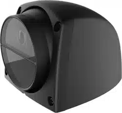
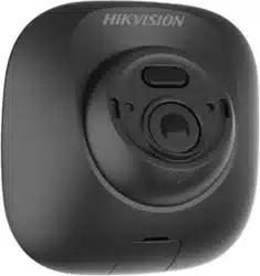
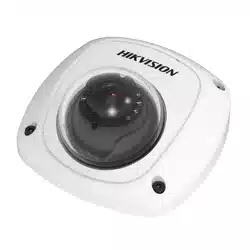
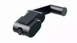
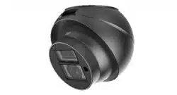
1.2 Overview
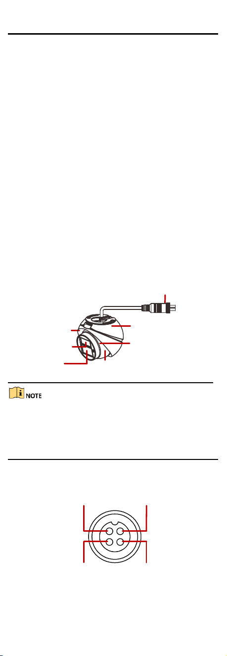
1.2.1 Overview of Vehicle-Mounted Camera
The overview of the camera is shown below.
Aviation Plug
Enclosure
Moun�ng Base
IR LED
Lens
Main Body
Pickup Hole
Figure 1-1 Overview
The camera with sound pickup func�on has a pickup hole
on the main body, shown in Figure 1-1 and this series
camera can only be used in the indoor facility. For the
camera without this func�on, it can be used in the
outdoor facility.
1.2.2 Interfaces of Avia�on Plug
The interfaces of avia�on plug are shown below.
Video Interface
Audio Interface Power Supply
GND
Interfaces of Avia�on PlugFigure 1-2
5
2 Installa�on
Before youstart:
Please make sure that the device in the package is in
good condi�on and all the assembly parts are included.
Make sure that all the related equipment is power-o
during the installa�on.
Check the specica�on of the products for the
installa�on environment.
Check whether the power supply is matched with your
power output to avoid damage.
Please make sure the wall is strong enough to
withstand four �mes the weight of the camera and the
moun�ng.
If the wall is the cement wall, you need to insert
expansion screws before you install the camera. If the
wall is the wooden wall, you can use self-tapping screw
to secure the camera.
If the product does not func�on properly, please
contact your dealer or the nearest service center. Do
not disassemble the camera for repair or maintenance
by yourself.
2.1 Ceiling Moun�ng
The installa�on steps of ceiling moun�ng are shown as
follows.
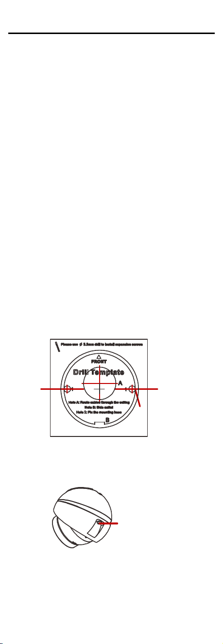
Step 1 Drill the screw holes according to the drill
template with Φ5.5mm electric drill.
Screw hole
Figure 2-1 The Drill Template
Step 2 Loosen the adjus�ng screw of the main body
with the allen wrench.
Adjus�ng Screw
Figure 2-2 Loosen the Adjus�ng Screw
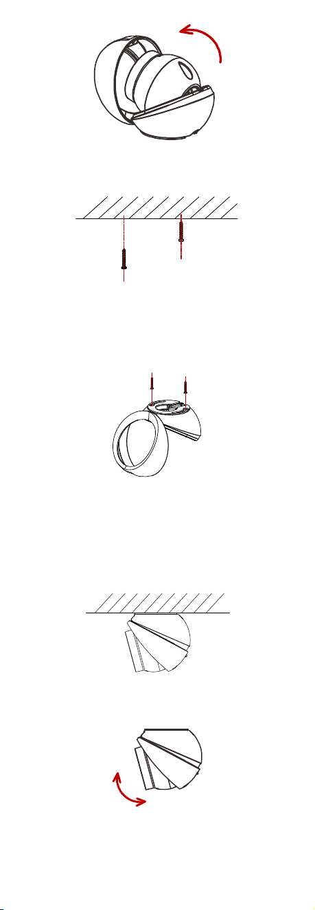
Open the enclosure to take out the camera.Step 3
6
Figure 2-3 Take Out the Camera
Step 4 Take 2 PA3X25 screws from the screw package
and insert 2/3 of it into the expansion screws.
Figure 2-4 Insert the Screws
Step 5 Align the holes of the moun�ng base to the
PA3X25 screws.
Step 6 Rotate the base to its appropriate posi�on.
Step 7 Tighten the PA3X25 screws.
Figure 2-5 Tighten the Screws
Step 8 Insert the main body of camera and insert the
adjus�ng screws for 2~3 threads with allen
wrench to make sure the main body doesn’t fall
o.
Step 9 Adjust the main body to the appropriate posi�on
and �ghten the adjus�ng screws.
Figure 2-6 Fix the Camera
Step 10 Adjust the camera according to the gure below
to get an op�mum angle.
50
°
0~
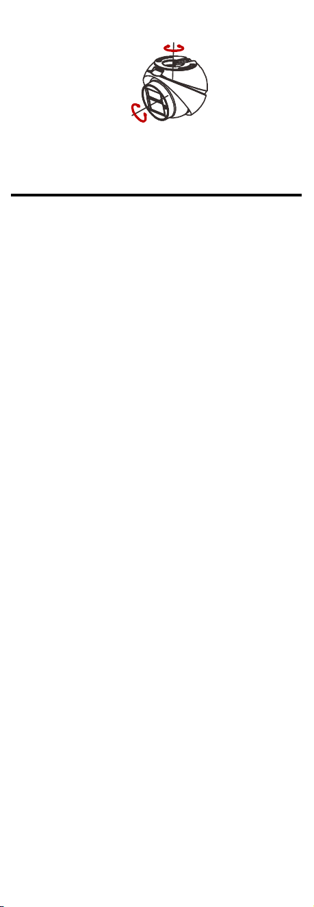
7
0
~360°
0
~50°
3-axis AdjustmentFigure 2-7
3 PTZ Control
The PTZ func�on is only supported in vehicle mounted
TVI dome camera, you can realize the control of IR LED
and mirror mode by calling presets.
3.1 IR LED Control
Enable IR LED
You can enable IR LED by calling preset No. 130.
Disable IR LED
You can disable IR LED by calling preset No. 131.
3.2 Mirror Mode
Disable Mirror Mode
You can disable mirror mode by calling preset No. 140.
Flip the Image Ver�cal
You can ip the image ver�cal by calling preset No.
141.
Flip the Image Horizontal
You can ip the image horizontal by calling preset No.
142.
Flip the Image Ver�cal and Horizontal
You can ip the image ver�cal and horizontal by
calling preset No. 143.