Loading ...
Loading ...
Loading ...
4
Table 3. The Run/Alarm Indicator Definition
No.
Indicator Light
Definition
1
Green LED Blink
Indicates the V-Power S05 is charging or discharging.
2
Green LED ON
Indicates the V-Power S05 is in standby mode.
3
Red LED Blink
Indicates the V-Power S05 is in alarm mode.
4
Red LED ON
Indicates an error has occur in the V-Power S05, which requires manual
operation or consultation with Vestwoods for maintenance.
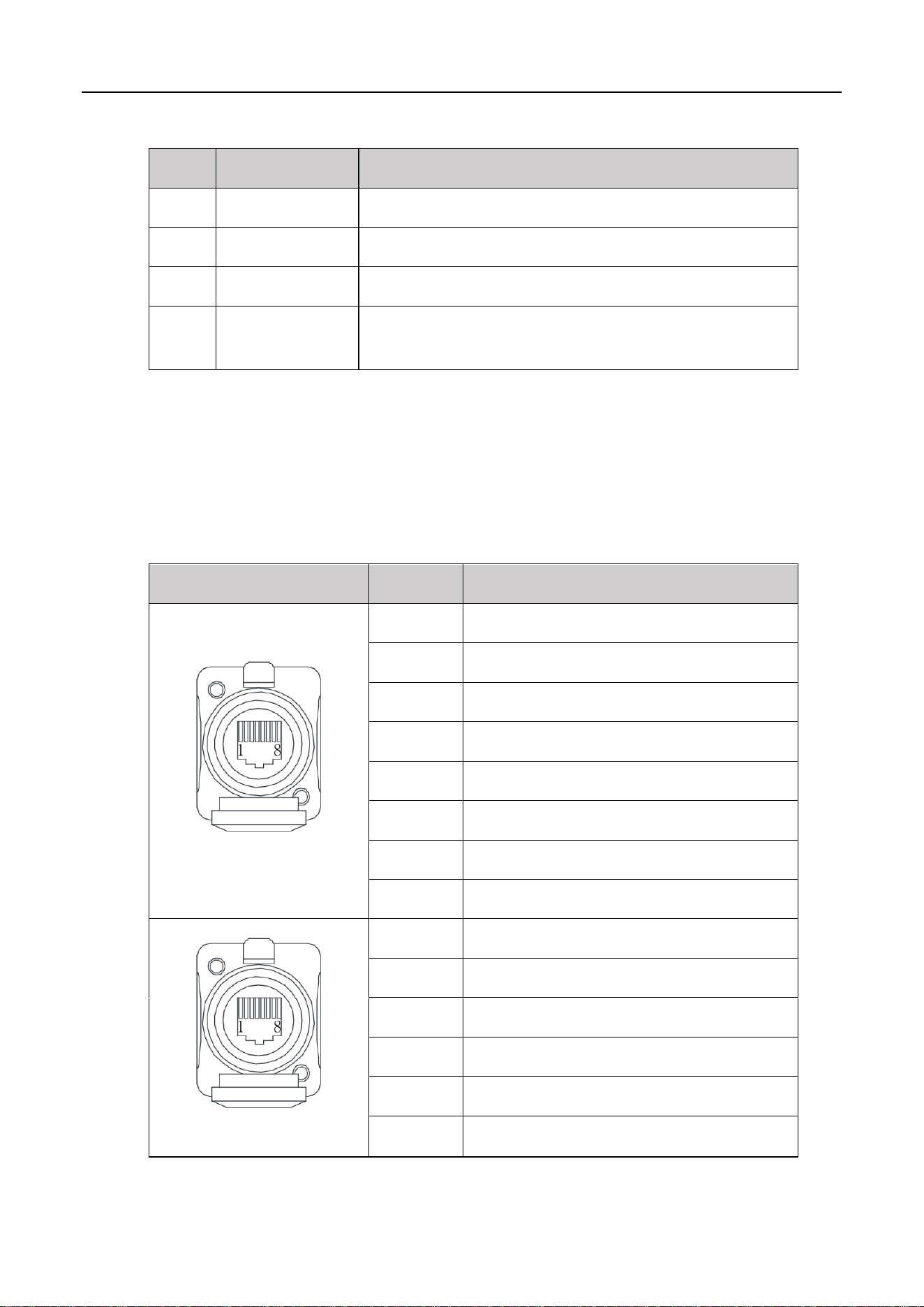
1.4 PIN Definition
V-Power S05 has 2 communication interfaces: COM1 and COM2, the PIN definition of COM ports are
shown as follows.
Table 4. The Communication Port Definition
COM1/2
Pin
Description
COM 1
1
RS485_B
2
RS485_A
3
CAN0-H (communicate with the last battery)
4
CAN1-H (communicate with inverter)
5
CAN1-L (communicate with inverter)
6
/
7
CAN0-L (communicate with the last battery)
8
/
COM 2
1
/
2
/
3
CAN0-H (communicate with the next battery)
4-6
/
7
CAN0-L (communicate with the next battery)
8
/
Loading ...
Loading ...
Loading ...