RESIDENTIAL ESS
LITHIUM-ION BATTERY SOLUTION
VE51100W
.•.
•
•
•
•
·•·
About This Document
Purpose
This document primarily introduces the main features, component composition, usage, installation, and
maintenance of Wall-mounted Residential Energy Storage System VE51100W (short for V-Power S05).
Intended Audience
This document is intended for:
Hardware installation engineers
Technical support engineers
Maintenance engineers
Users
Symbol Conventions
The symbols that may be found in this document are defined as follows.
Symbol
Definition
Remarks
Danger
Indicates a hazard with a high level of risk which, if not avoided, will
result in death or serious injury.
Warning
Indicates a hazard with a medium level of risk which, if not avoided,
could result in death or serious injury.
Attention
Indicates a hazard with a low level of risk which, if not avoided,
could result in minor or moderate injury.
Note
Supplements the important information in the main text.
NOTE is used to address information not related to personal injury,
equipment damage, and environmental deterioration.
Change History
Changes between the issued documents are cumulative. The latest document issued contains all the
changes made in earlier versions.
Issue 01 (2023-06-15)
This issue is the first official release.

Contents
1 Introduction .............................................................................................................................. 1
1.1 Application ............................................................................................................................................... 1
1.2 Appearance .............................................................................................................................................. 1
1.3 Panel Introduction .................................................................................................................................... 2
1.4 PIN Definition ........................................................................................................................................... 4
1.5 Lithium-ion Cell ........................................................................................................................................ 5
1.6 Technical specifications ............................................................................................................................ 6
2 Installation ................................................................................................................................ 8
2.1 Precautions for Installation ...................................................................................................................... 8
2.2 Preparing for Installation .......................................................................................................................... 8
2.2.1 Tools ................................................................................................................................................................. 8
2.2.2 Packing List ....................................................................................................................................................... 9
2.2.3 Unpacking Acceptance ................................................................................................................................... 10
2.3 Installing Guide ....................................................................................................................................... 10
2.4 Connecting Power Cable ........................................................................................................................ 13
2.5 Connecting Communication Cable ......................................................................................................... 16
3 Operation................................................................................................................................ 20
3.1 Check before Power-on .......................................................................................................................... 20
3.2 Power-on ................................................................................................................................................ 20
3.3 Operation Guide ..................................................................................................................................... 22
4 Maintenance ........................................................................................................................... 23
4.1 V-Power S05 Storage .............................................................................................................................. 23
4.2 Monthly Maintenance ............................................................................................................................ 23
4.3 Quarterly Maintenance .......................................................................................................................... 24
4.4 Yearly Maintenance ................................................................................................................................ 24
4.5 Alarm Handling ....................................................................................................................................... 24
Acronyms and Abbreviations ...................................................................................................... 26
1
1 Introduction
1.1 Application
V-Power S05 is a next-generation product developed by Vestwoods, which is used in residential energy
storage solutions. This battery system has a capacity of 5.12 kWh.
V-Power S05 integrates the high-performance BMS. It has multiple protection functions to extend battery
life, such as system over-charge, system over-discharge, cell over-voltage, cell under-voltage, charging
over-current, discharging over-current, and insulation fault protections. It also has RS485 and CAN
communication to read battery module’s real-time data.
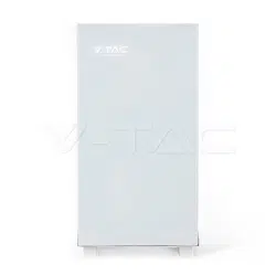
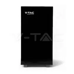
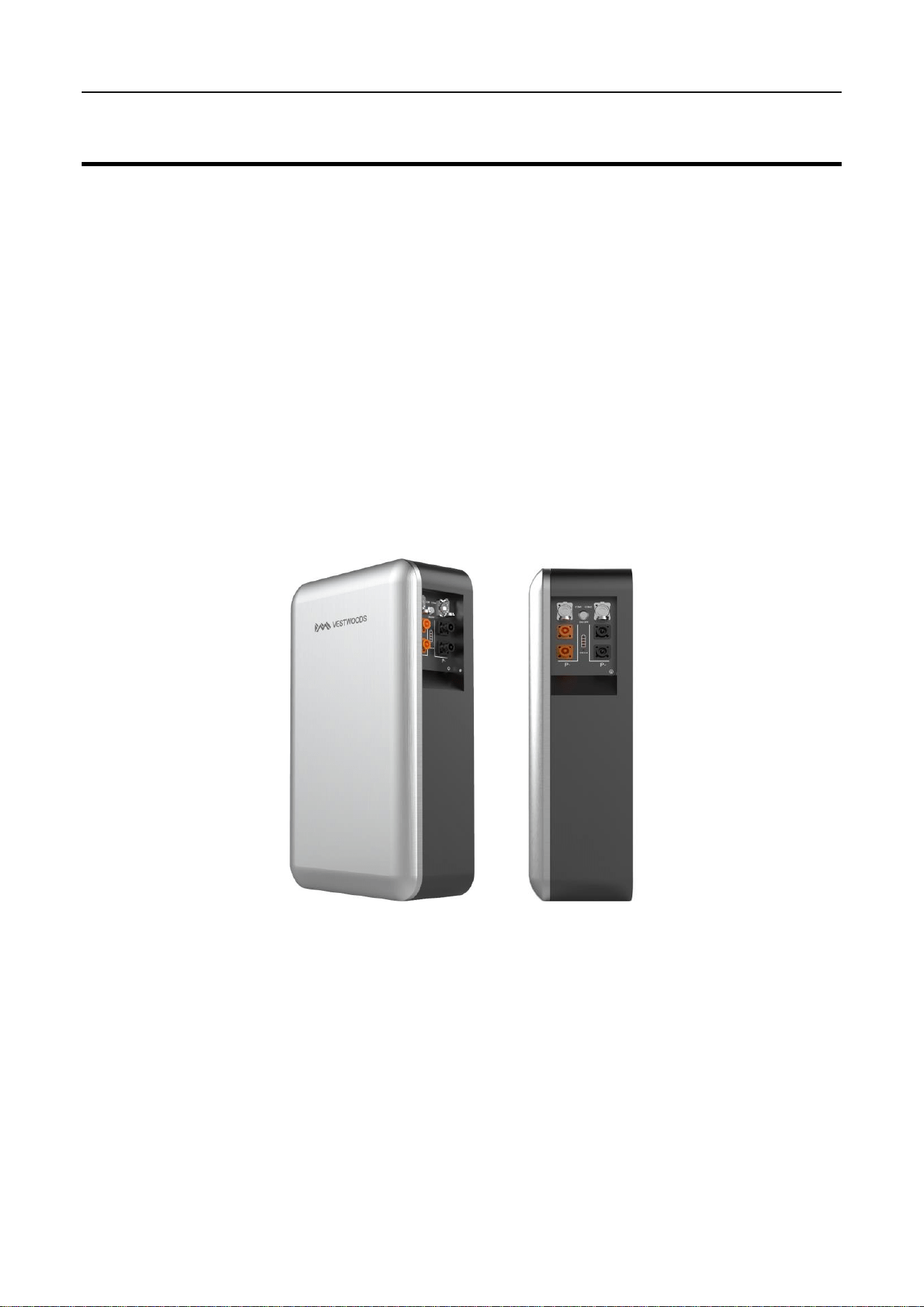
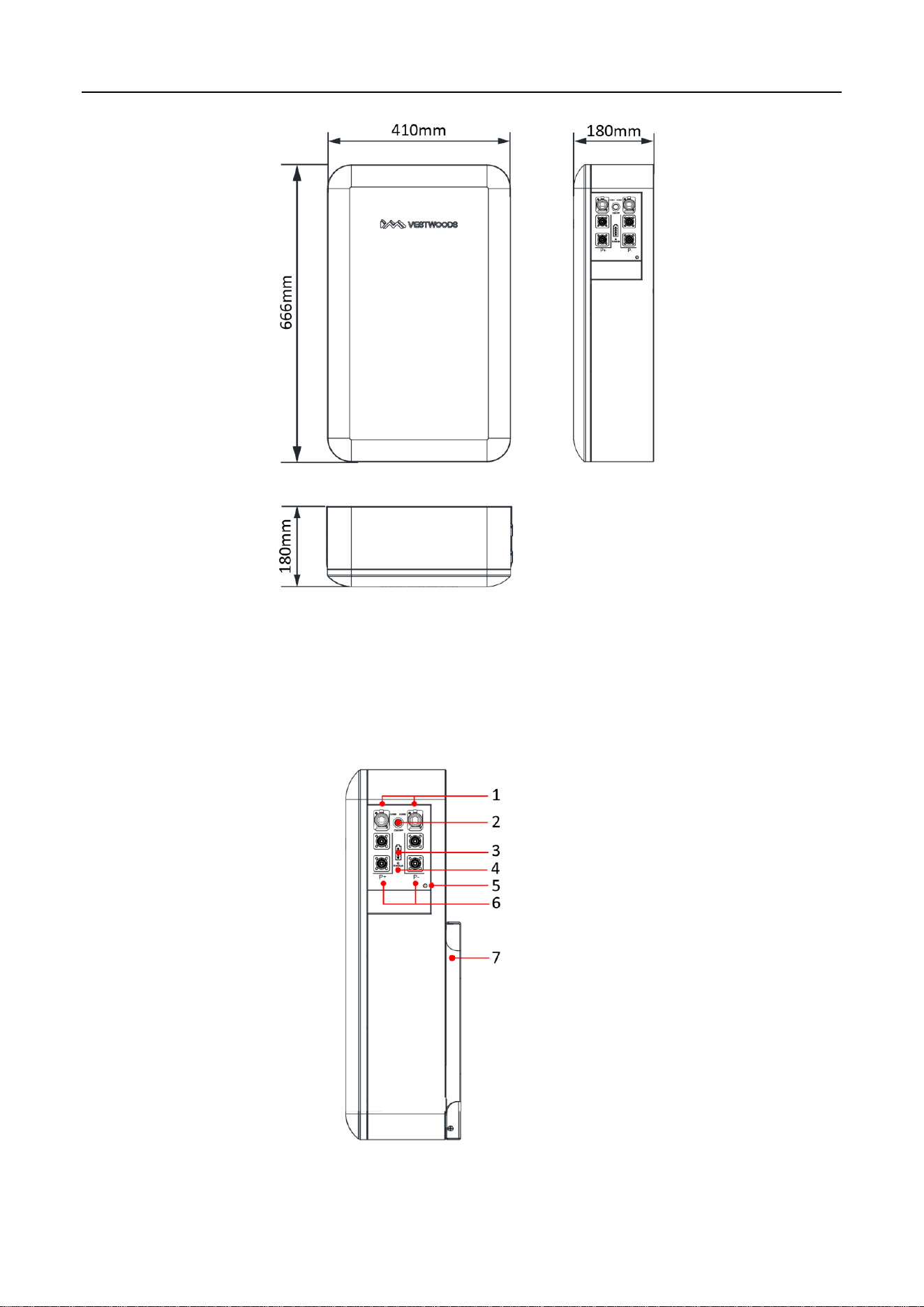
1.2 Appearance
The appearance of V-Power S05 is shown as follows.
Figure 1. V-Power S05 appearance
The V-Power S05 dimensions are shown as follows.
2
Figure 2. V-Power S05 dimensions (unit: mm)
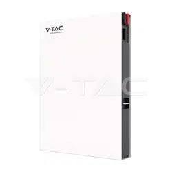
1.3 Panel Introduction
The V-Power S05 operation panel is shown as follows.
Figure 3. V-Power S05 operation panel
3
The definition of the V-Power S05 operation panel is shown as follows.
Table 1. Operation Panel Interface Definition
No.
Items
Remark
1
COM 1/COM 2
2*RJ45 Interface for communication:
COM1 for communication with inverter or the last battery;
COM2 for communication with the next battery.
2
POWER
Power switch.
3
SOC
State of charge.
4
RUN/ALM
Indicate battery module running or alarm status.
5
GND
Grounding.
6
Output connectors
Battery module output connectors.
7
Bracket
Mounting bracket.
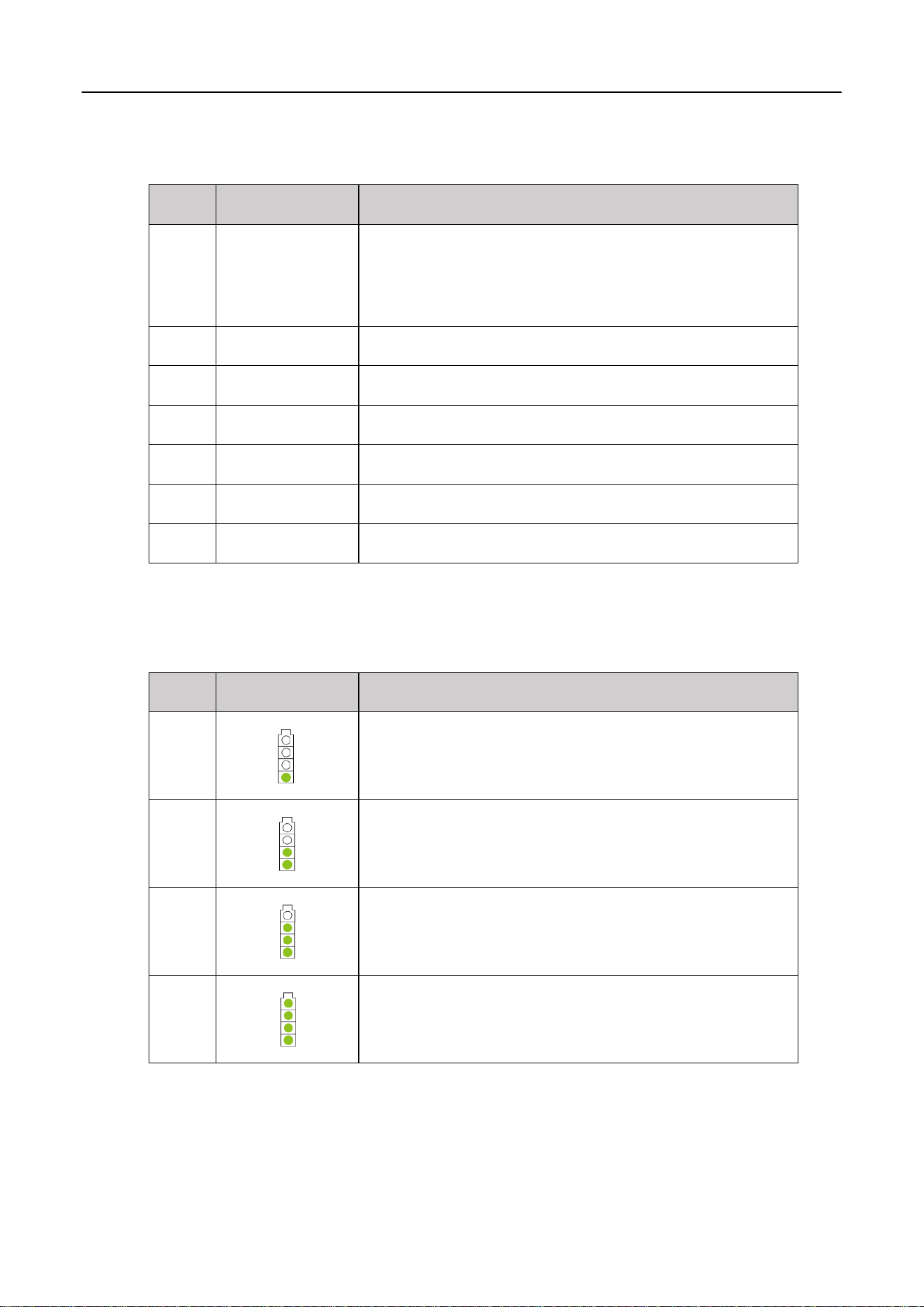
The SOC indicator used to identify the current capacity status of the battery. The number of blinking
indicators corresponds to different remaining capacity. The specific meaning is shown as follows.
Table 2. The SOC Indicator Definition
No.
Indicator Light
Remark
1
0% < SOC ≤ 25%
2
25% < SOC ≤ 50%
3
50% < SOC ≤ 75%
4
75% < SOC ≤ 100%
The corresponding relationship between operation status and indicator operation status is shown as
follows.
4
Table 3. The Run/Alarm Indicator Definition
No.
Indicator Light
Definition
1
Green LED Blink
Indicates the V-Power S05 is charging or discharging.
2
Green LED ON
Indicates the V-Power S05 is in standby mode.
3
Red LED Blink
Indicates the V-Power S05 is in alarm mode.
4
Red LED ON
Indicates an error has occur in the V-Power S05, which requires manual
operation or consultation with Vestwoods for maintenance.
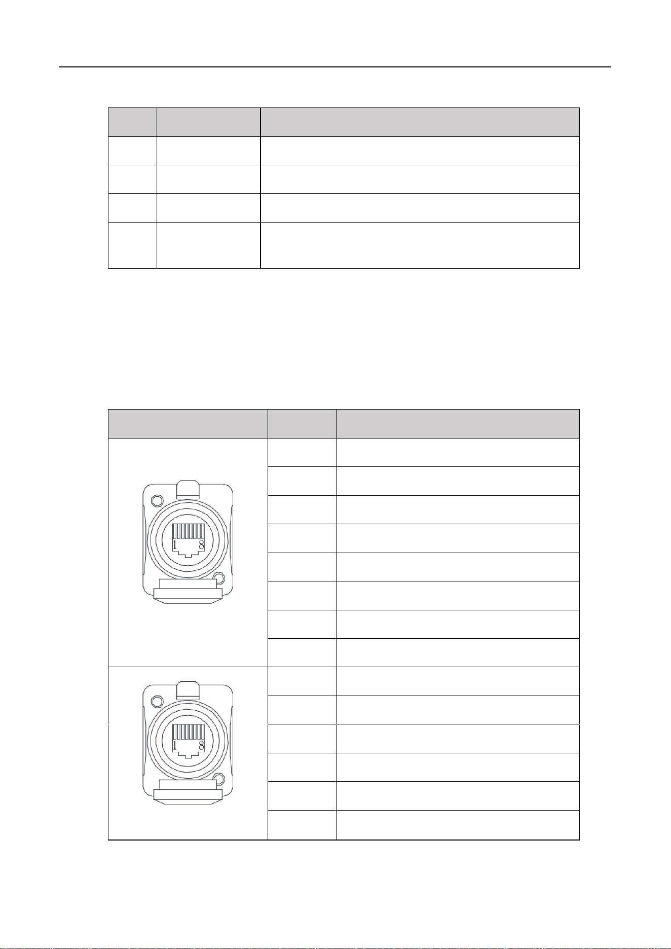
1.4 PIN Definition
V-Power S05 has 2 communication interfaces: COM1 and COM2, the PIN definition of COM ports are
shown as follows.
Table 4. The Communication Port Definition
COM1/2
Pin
Description
COM 1
1
RS485_B
2
RS485_A
3
CAN0-H (communicate with the last battery)
4
CAN1-H (communicate with inverter)
5
CAN1-L (communicate with inverter)
6
/
7
CAN0-L (communicate with the last battery)
8
/
COM 2
1
/
2
/
3
CAN0-H (communicate with the next battery)
4-6
/
7
CAN0-L (communicate with the next battery)
8
/
5
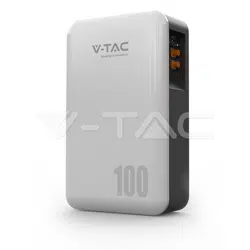
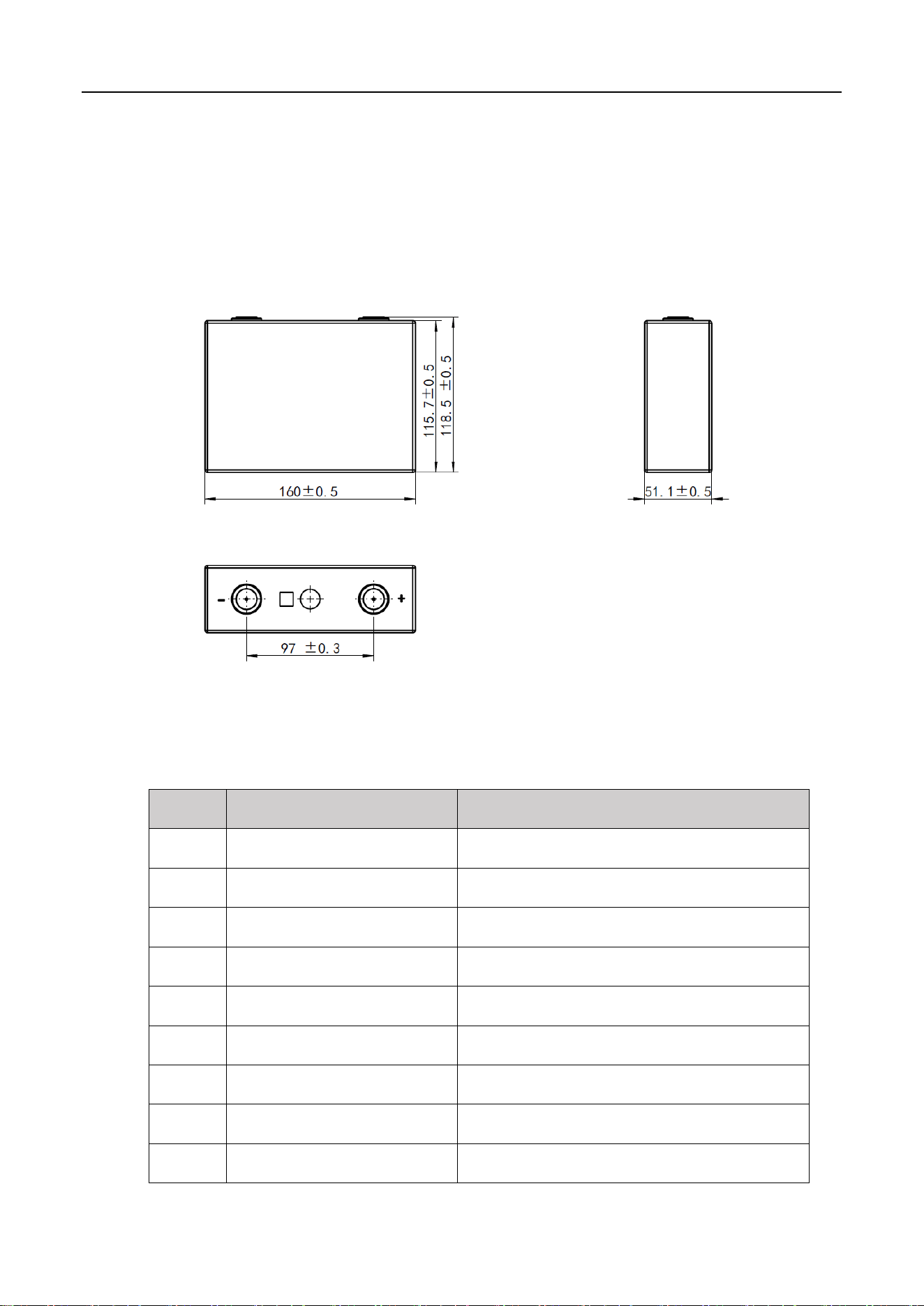
1.5 Lithium-ion Cell
The Lithium-ion cell selected in the scheme is a special energy-type lithium battery product. This series of
Lithium-ion cells have high specific energy, longer cycle life, low cost, capable of high current charge and
discharge, high-temperature tolerance, high energy density, safety, and pollution-free features.
Lithium-ion cell's three views are shown as follows.
Figure 4. Lithium-ion cell three views (unit: mm)
Lithium-ion cell main technical specifications are shown as follows.
Table 5. Lithium-ion cell main technical specifications
No.
Items
Parameter
1
Battery type
LiFePO
4
2
Nominal voltage
3.2 V
3
Nominal capacity
100 Ah
4
Nominal energy
0.32 kWh
5
Max. continuous charge current
100 A
6
Max. continuous discharge current
100 A
7
Charging cut-off voltage
3.65 V
8
Discharging cut-off voltage
2.50 V
9
Operating charging temperature
0℃-50℃

6
No.
Items
Parameter
10
Operating discharging temperature
-20℃-55℃
11
Storage temperature
0-45℃ (less than 1 month) ;
0-35℃ (less than 12 months)
12
Allowable relative humidity
5% ~ 95% Non-condensing
13
Dimensions (Width*High*Depth)
160.0 × 115.7 × 51.1 mm
14
Weight
Approx. 1.92 kg
1.6 Technical specifications
The V-Power S05's main technical specifications are shown as follows.
Table 6. V-Power S05 technical specifications
No.
Items
Parameter
1
Model
VE51100W
2
The number of cells
16
3
Configuration
1P16S
4
Nominal voltage
51.2 V
5
Nominal capacity
100 Ah
6
Total energy
5.12 kWh
7
Charging cut-off voltage
57.6 V
8
Discharging cut-off voltage
42.0 V
9
Max. continuous charge current
100 A
10
Max. continuous discharge current
100 A
11
Communication method
CAN/RS485
12
Max. number of modules allowed to
be connected in parallel
Parallel expandable, ≤ 16 groups, without derating.
More than 16 groups need to be derated.
13
Storage temperature
0℃~ 45℃
14
Operating temperature
Discharge -20℃ ~ 55°C, Charge 0°C ~50℃

7
No.
Items
Parameter
15
SOC estimation value
<8%
16
Allowable relative humidity
5% ~ 95% Non-condensing
17
Altitude
2000m without derating
18
Cooling method
Natural heat dissipation
19
Protection level
IP65
20
External Interface
Battery positive and negative quick plug terminals:
2*P+, 2*P-
Communication standard RJ45 port:2*RJ45
21
Installation method
Wall-mounted/Standed
22
Display method
Indicator light (power, operation status)
23
Dimensions (Width*High*Depth)
410 × 666 × 180 mm (without wall bracket and base)
24
Net weight
Approx. 49 kg
Protection function
25
Over-voltage protection
System over-voltage, cell over-voltage
26
Under-voltage protection
System under-voltage, cell under-voltage
27
Over-current protection
Charging over-current, discharging over-current
28
Temperature protection
Charging high temperature, charging low temperature,
discharging high temperature, discharging low
temperature
29
Short circuit protection
BMS hardware protection, external fuse
30
Reverse connection protection
Available, when it is powered off
31
Dielectric withstand test
Available
32
Pre-charge function
Available
33
Equalization function
Available
34
Hibernation function
Available
8
2 Installation
2.1 Precautions for Installation
Light intensity is required near the installation location.
Comply with the safety operation technical regulations when lifting and handling heavy objects.
Equipment and tools must be complete, intact, and reliable. It is strictly prohibited to use tools with
cracks, burrs, loose handles, etc., that do not meet the safety standards.
Installation operations must be guided by qualified engineers.
During installation, two people must work together, one operating and the other inspecting.
The original cable connection and operation process shall not change without the authorization of
the company's consent.
2.2 Preparing for Installation
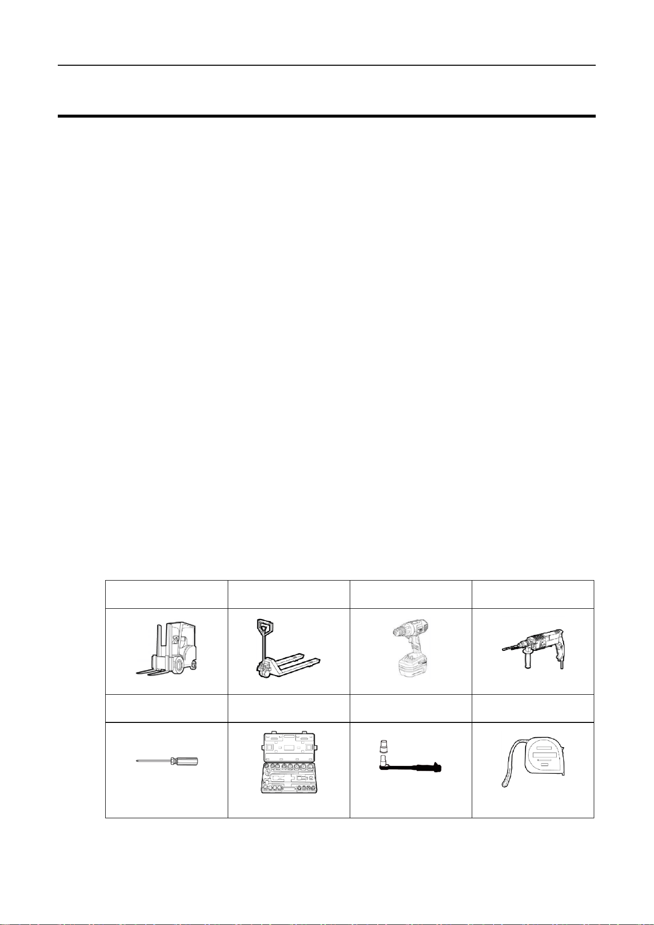
2.2.1 Tools
Insulated installation tools must be used to prevent electric shocks. If tools without insulation protection
are used, the exposed metal parts must be wrapped and insulated with insulating tape.
The following table shows tools that need to be prepared before installation.
Table 7. Tools
Electric forklift
Manual forklift
Electric screwdriver
Impact drill
Phillips screwdriver
Socket wrench
Insulated torque wrench
Tape measure
9
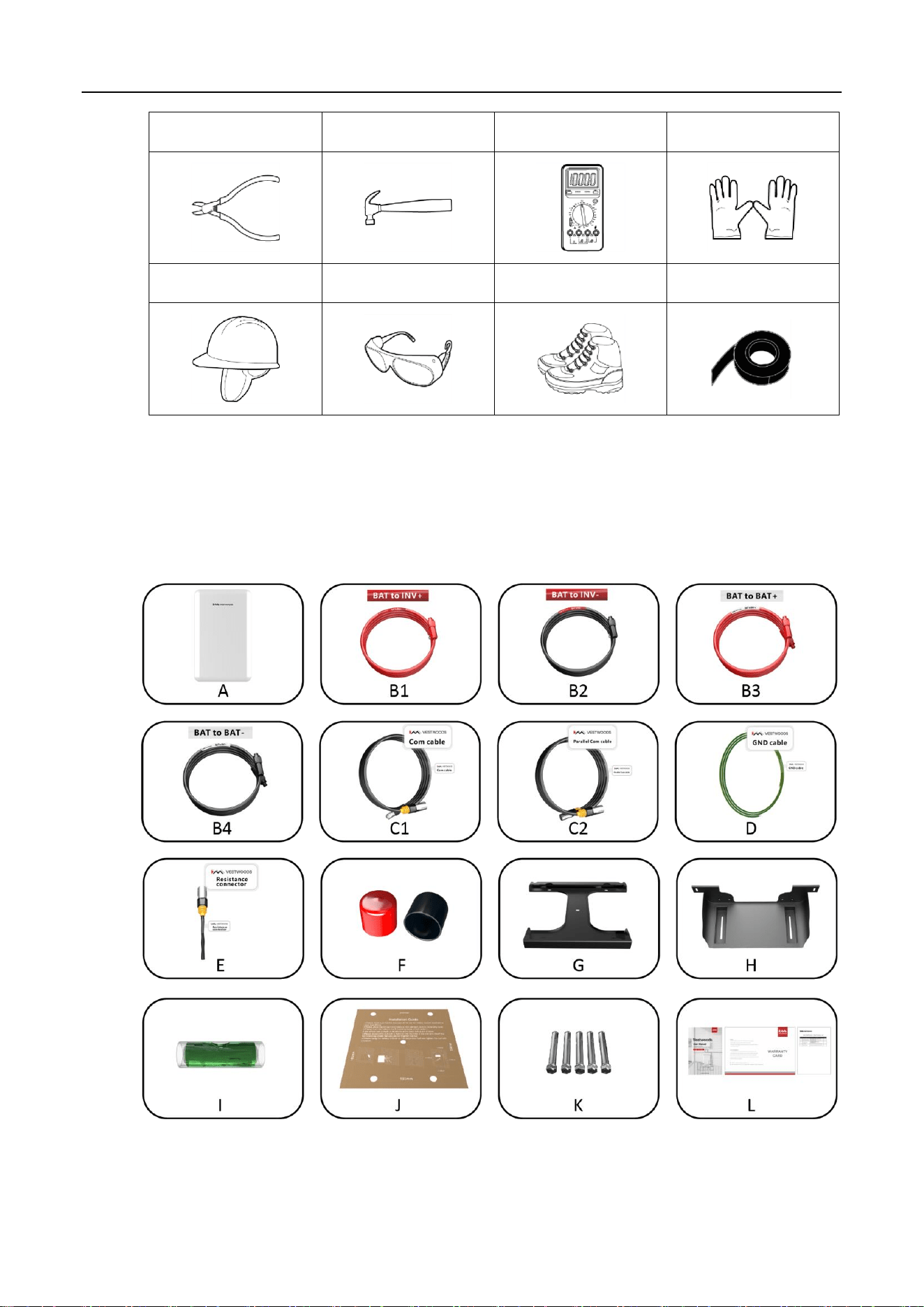
Diagonal pliers
Claw hammer
Multimeter
Anti-static gloves
Helmet
Goggle
Insulation shoes
Insulating tape
2.2.2 Packing List
Open the package and take out the product, please check the accessories first. The packing list is shown
below.
Figure 5. Accessories of V-POWER S05

10
Item
Description
Quantity
A
Lithium battery pack
1
B1
Positive output power cable
1
B2
Negative output power cable
1
B3
Positive power parallel cable (*Optional)
1
B4
Negative power parallel cable (*Optional)
1
C1
Communication cable
1
C2
Parallel communication cable(*Optional)
1
D
GND cable
1
E
Resistance connector
1
F
Protection cover, red & black
2
G
Mounting bracket
1
H
Mounting base(*Optional)
1
I
Spirit level
1
J
Positioning sample
1
K
Expansion screw, M8*60
5
L
User manual /Warranty card/Packing List
1
2.2.3 Unpacking Acceptance
After receiving the goods on-site, please check whether the packing box is intact and inspect the goods
in time. If the packing box is slightly damaged, please sign the cargo list to confirm receipt and indicate
the extent of the damage. If the damage of the packing box is serious, please refuse to sign.
Please carry out an unpacking inspection after receiving all the goods. If users find that the received
goods do not match the packing list, please contact Vestwoods as soon as possible.
2.3 Installing Guide
Context
Before installing the V-Power S05, users need to plan the installation site. The installation site should
comply with the following conditions:
The installation site should be able to place one V-Power S05, and there should be a wall to mount
the inverter. It is recommended that the wall can bear more than 200 kg.
A 500 mm ventilation and operation space should be reserved at the right of the V-Power S05.
11
If possible, the installation site should be as spacious and ventilated as possible. If the site is small
and confined, please configure auxiliary heat dissipation equipment.
Procedure
1 Take out the V-Power S05 and put it in the installation place.
The V-Power S05 is heavy. If possible, please use tools to assist in handling and installation.
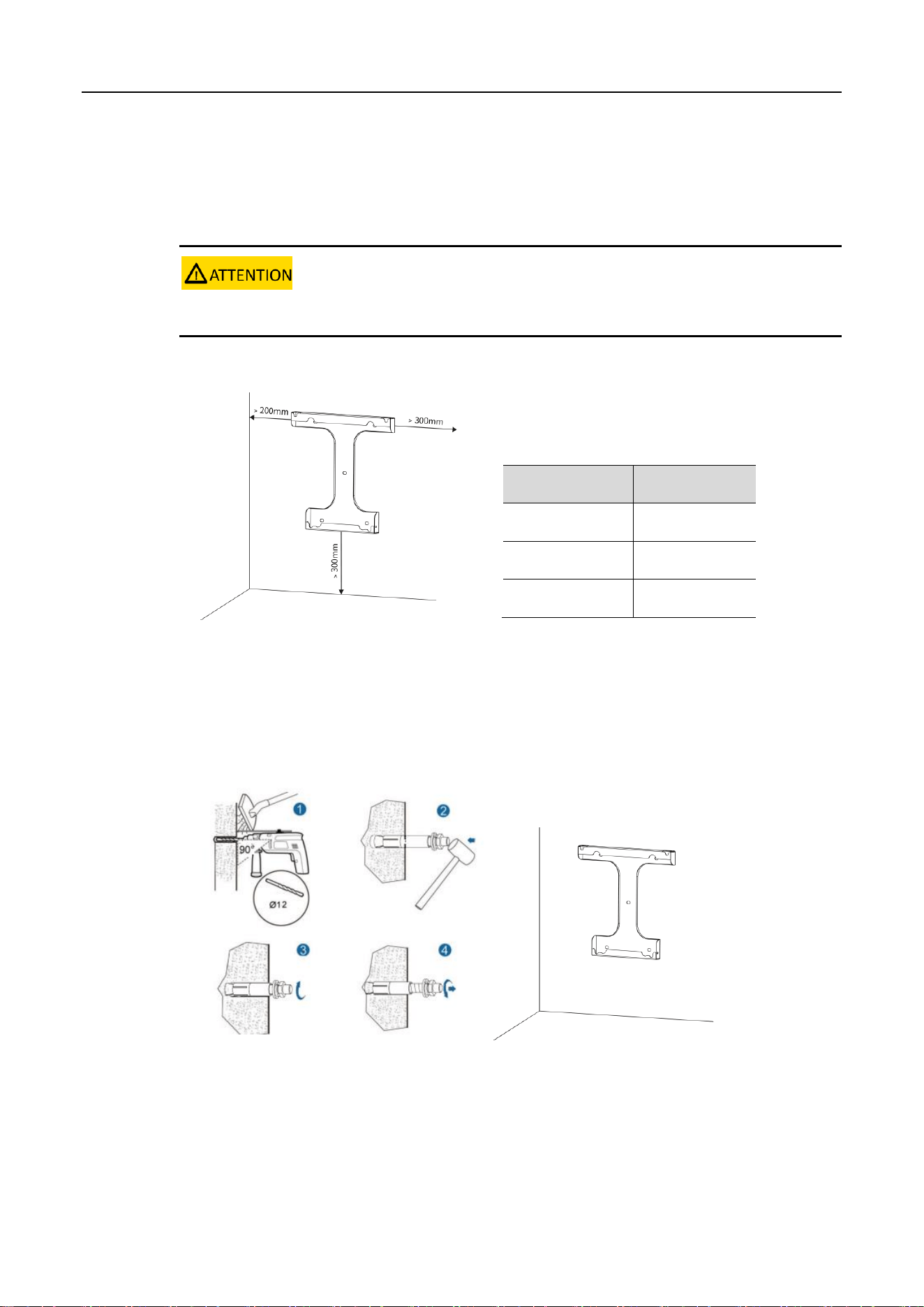
2 Plan the installation site.
Figure 6. Planning installation site
3 Using a drill and level, mount the bracket to the selected wall.
Figure 7. Mounting the bracket
4 Check whether the bolt torque of the nuts (4 nuts on the back of V-Power S05) is 8 N.m.
Table 8. Installation Space Requirement
Position
Min. distance
Left-side
200 mm
Right-side
300 mm
Bottom
300 mm
12
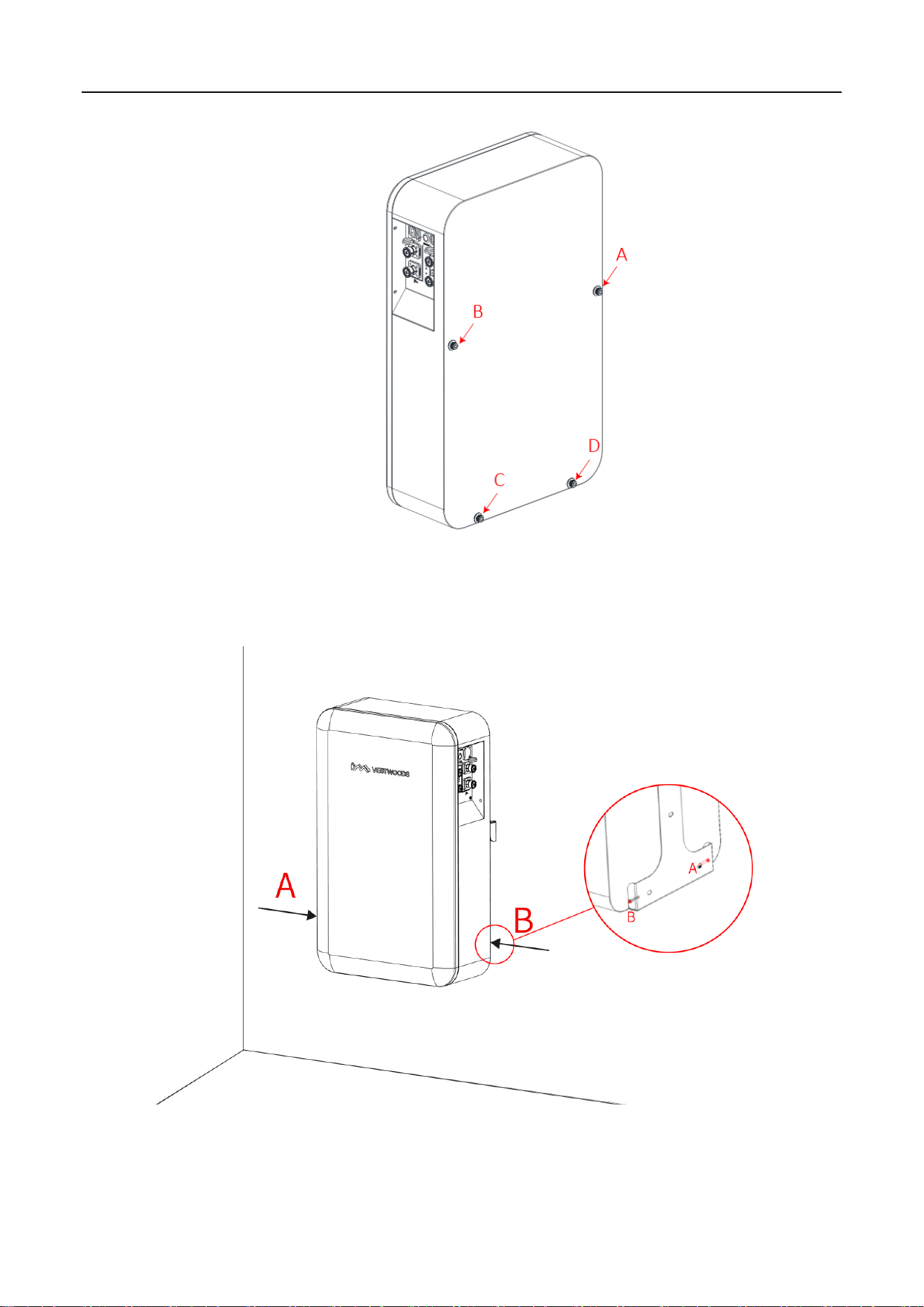
Figure 8. Bolt torque confirmation
5 Mount the V-Power S05 on the mounting bracket and fix it with original M5 screws on both sides.
Figure 9. Mounting V-Power S05
6 Connect the ground wire to the ground.
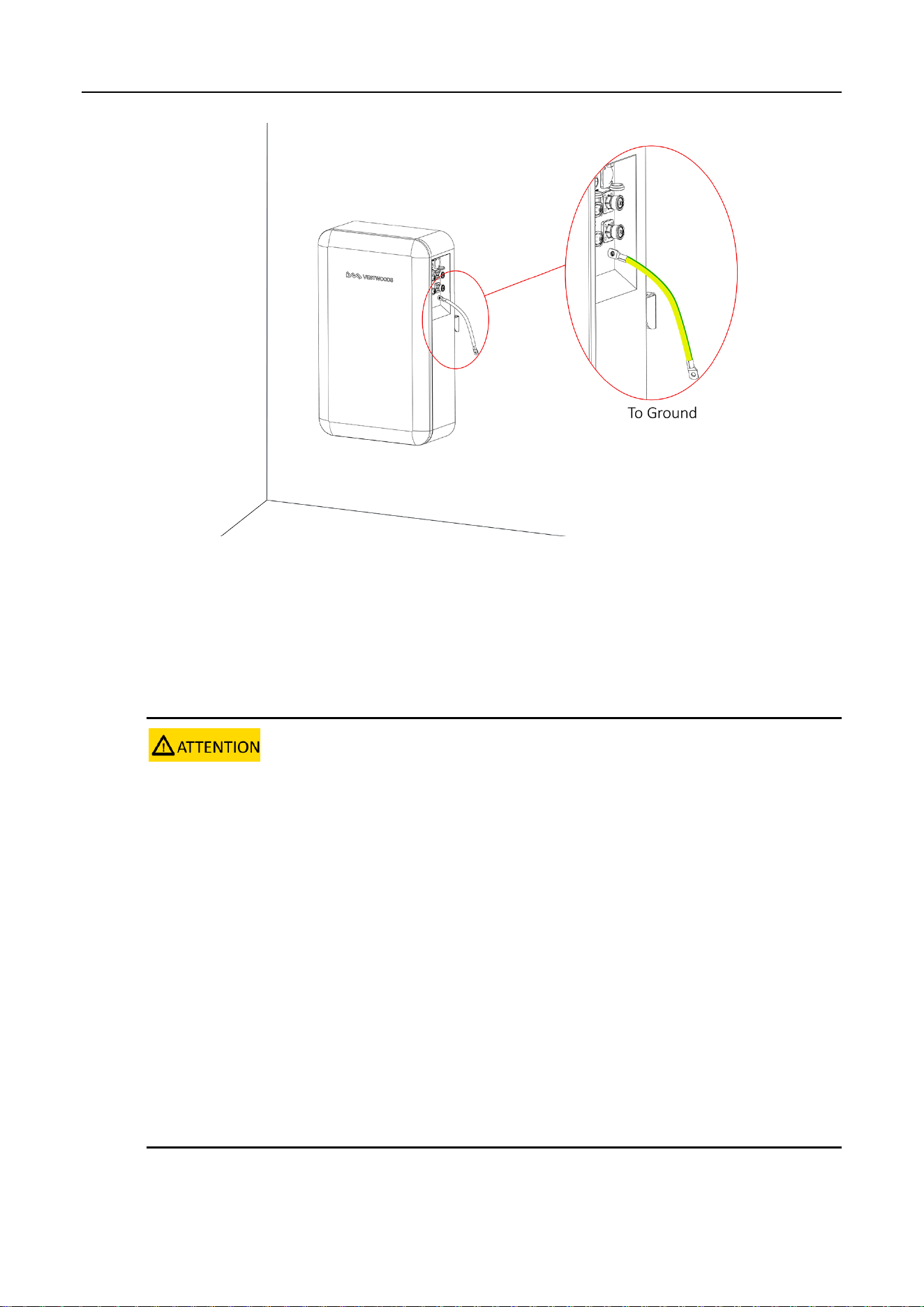
13
Figure 10. V-Power S05 grounding
2.4 Connecting Power Cable
Context
1. Insulate installation tools to prevent electric shocks.
2. According to the power value of the inverter used, the number of battery configurations should match the following
minimum number of parallel connections:
a. When the inverter power ≤ 5kW: need to configure at least one VE51100W battery.
b. When 5kW < inverter power ≤ 10kW: need to configure at least two VE51100W batteries (connect in parallel).
3. According to the power value of the inverter used, two ways are shown to connect the power cable when batteries
are used in parallel:
a. When the inverter power ≤ 10kW, multiple batteries are used in parallel, connect the power cable base on the
Figure 13~15 wiring method.
b. When 5kW < inverter power ≤ 10kW, multiple batteries are used in parallel, a "Junction Box" is required, first
connect the power cable of each battery to the junction box, then connect the power cable from the junction box to the
inverter.
14
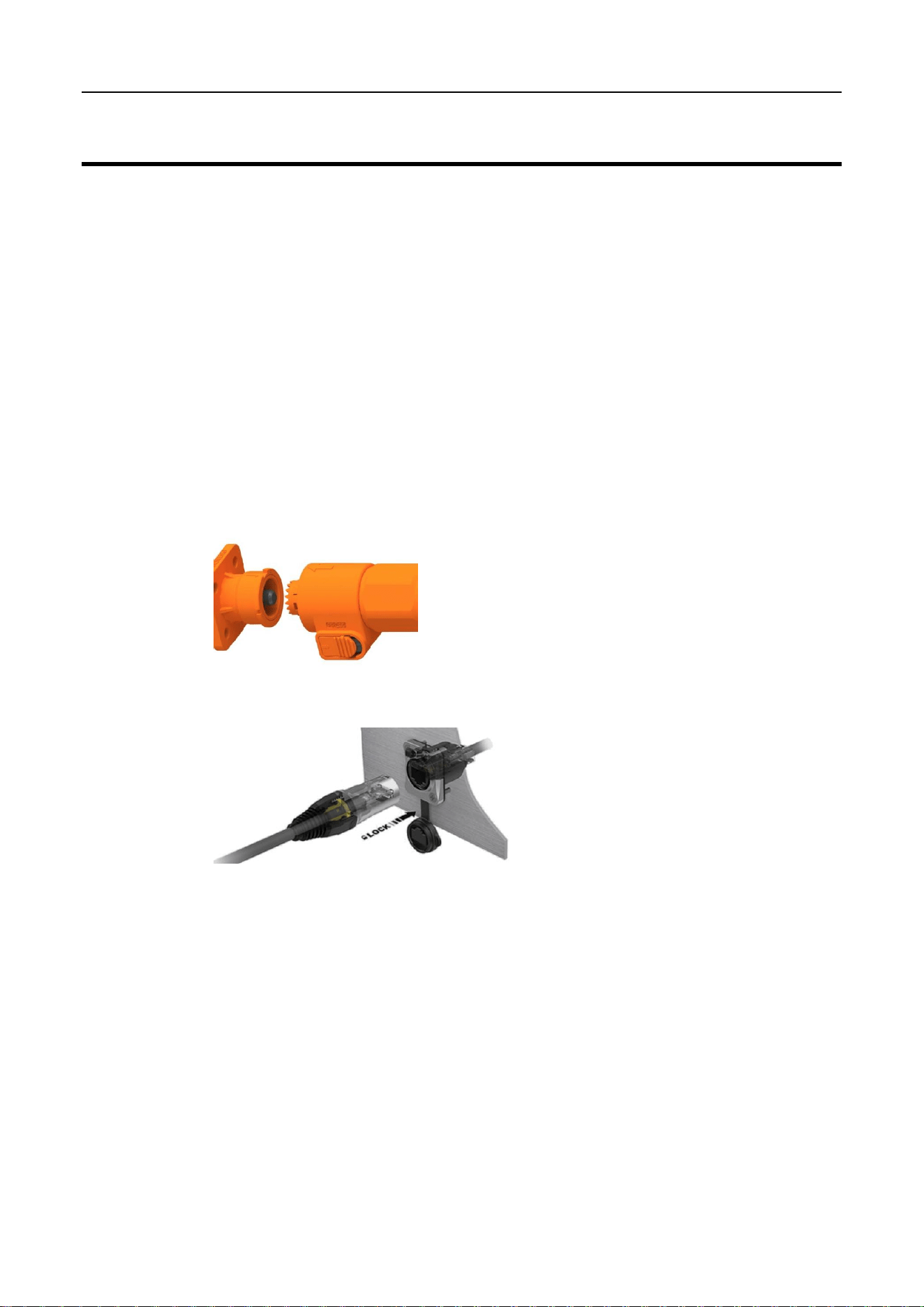
The V-Power S05’s power cable connection method adopts a self-locking connector. The description of
the self-locking connector is shown as follows:
The steps for connecting the self-locking connector are as follows:
A Adjust the direction of the self-locking connector to align with the battery module terminal.
B Rotate the self-locking connector slightly, and it will be inserted automatically.
C After the self-locking connector is automatically inserted, push it in slightly, and after hearing a
click sound, the self-locking connector and the V-Power S05 terminal are connected.
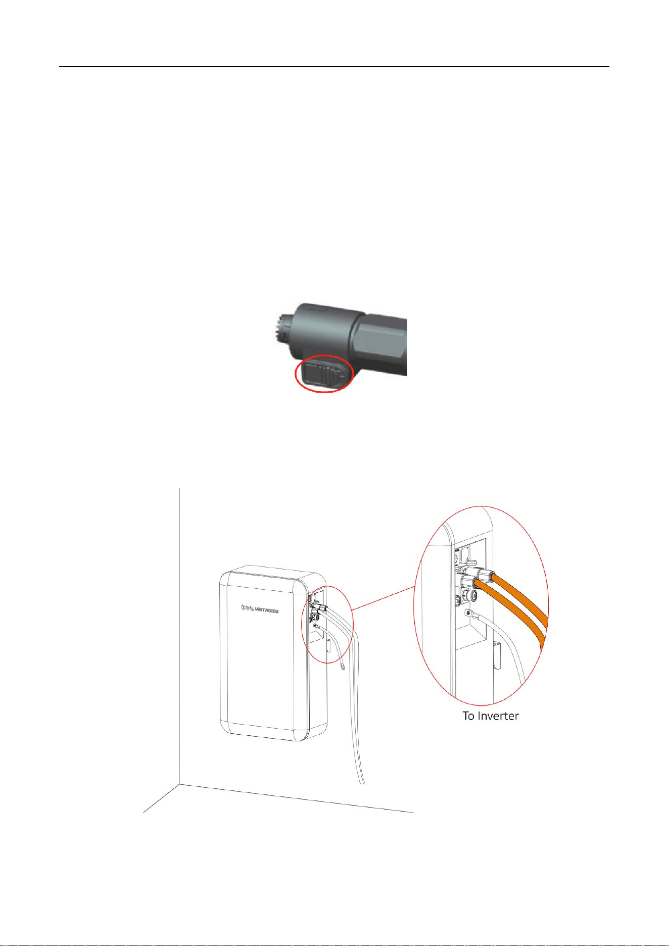
Need to press the button on the self-locking connector simultaneously when users need to pull out
the self-locking connector.
Figure 11. Self-locking connector button
Procedure
1 Connect the power cables of the V-Power S05.
Figure 12. Connect the external cables
15
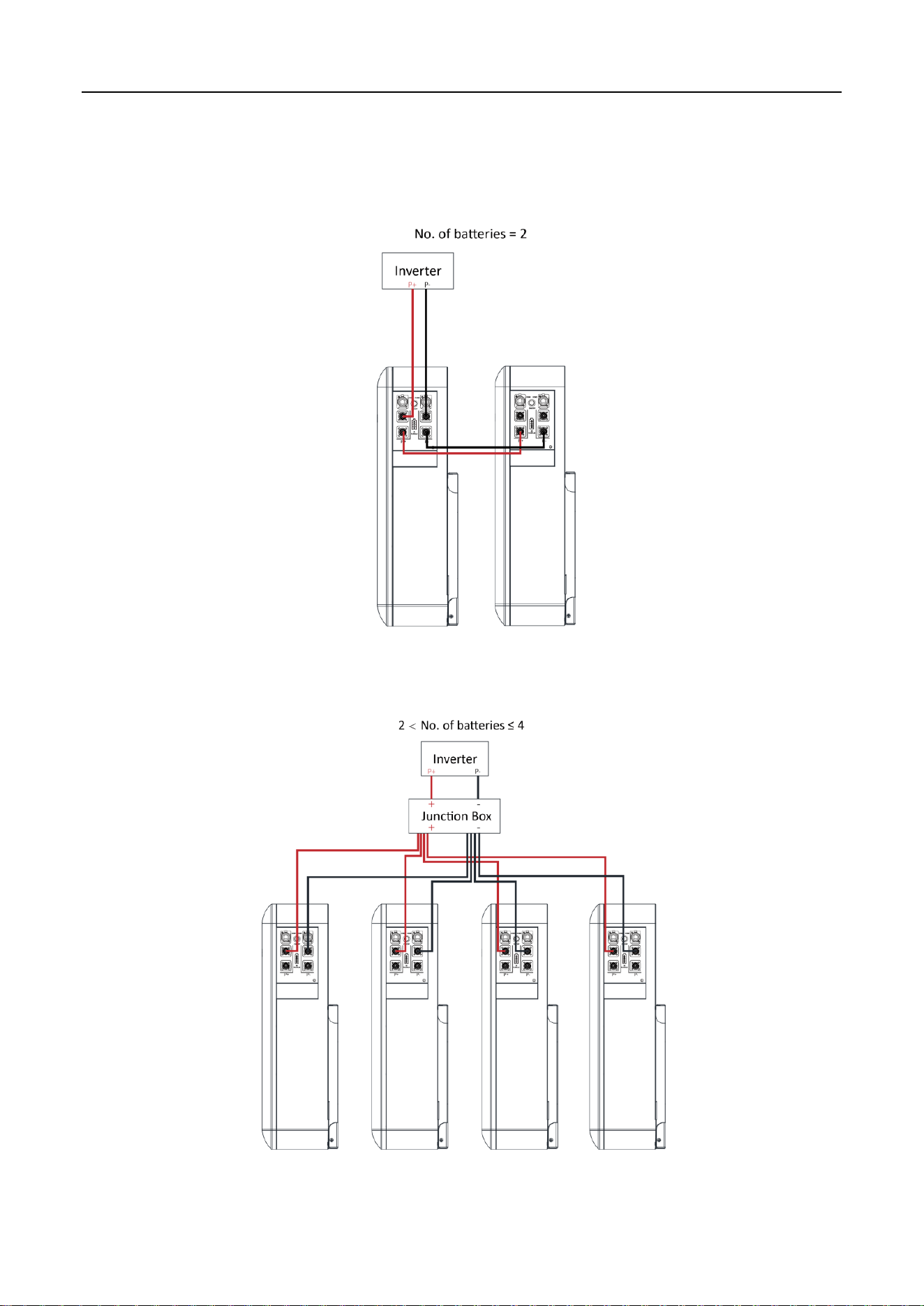
If there are multiple V-Power S05 in parallel, you need to connect the batteries in parallel using the
parallel power cables, then connect the power cables to the inverter. Please pay attention to the
distinction between battery modules’ positive and negative terminals.
Figure 13. Connect the power cables (Battery=2)
Figure 14. Connect the power cables (2 < Batteries ≤ 4)
16
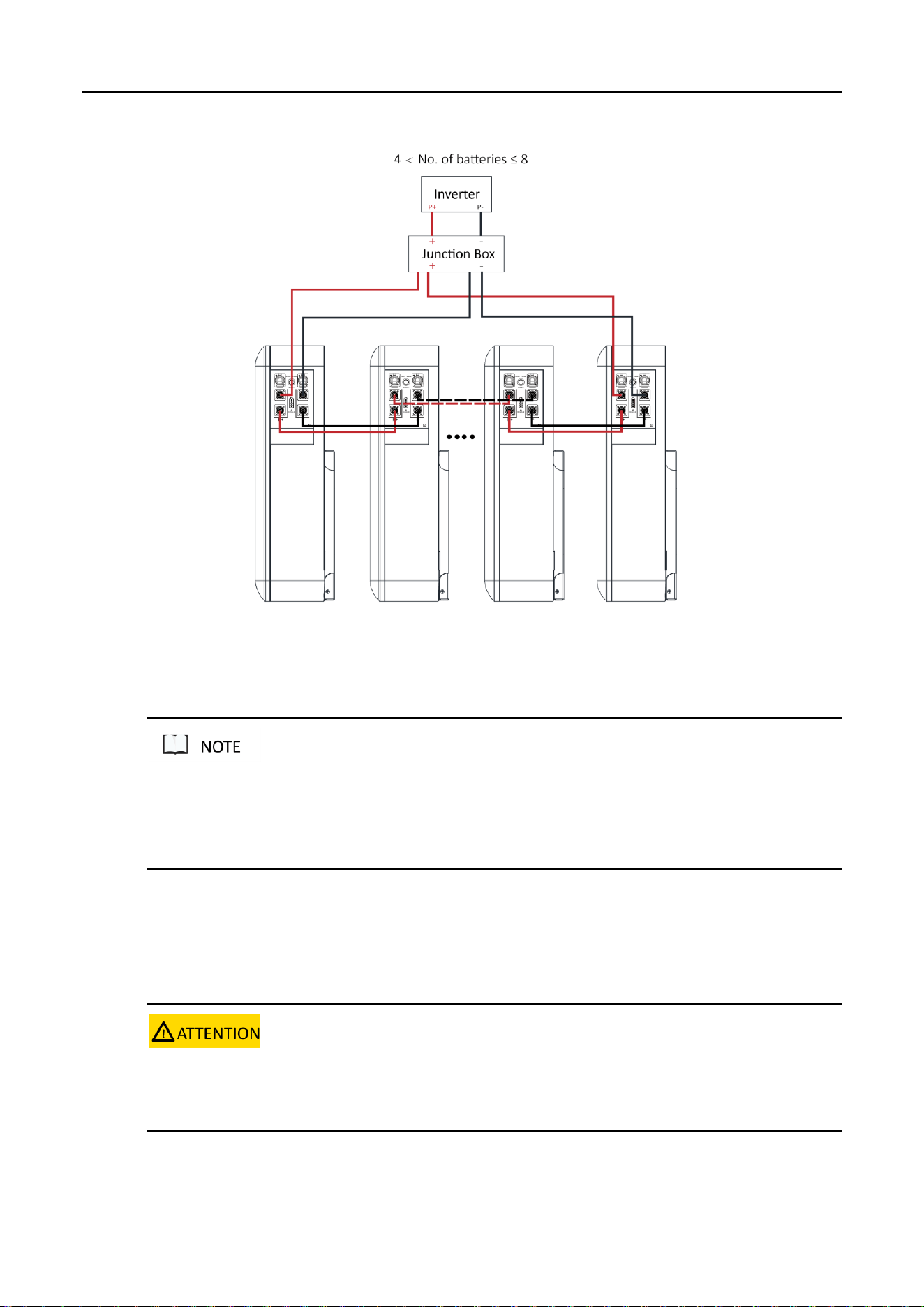
Figure 15. Connect the power cables (4 < Batteries ≤ 8)
The self-locking connector's color should correspond to the battery module terminal's color: orange corresponds
to the positive pole, and black corresponds to the negative pole.
Please take care of the removed battery module protective cover in case of backup.
2.5 Connecting Communication Cable
Context
Please pay attention to the direction when plugging the communication cable connector, do not operate violently.
Communication cables and power cables must be routed separately.
Procedure
17
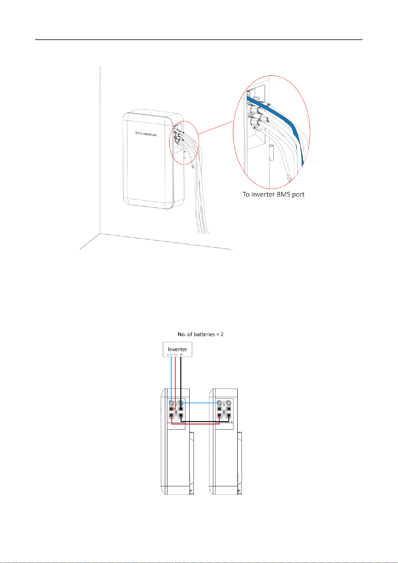
1 Connect the communication cables of the V-Power S05.
Figure 16. Connect the communication cables
If there are multiple V-Power S05 in parallel, you need to connect the communication cables in parallel
first. Then connect the communication cable between the inverter and COM1 of the first V-Power S05.
Figure 17. Connect the communication cables (Battery=2)
18
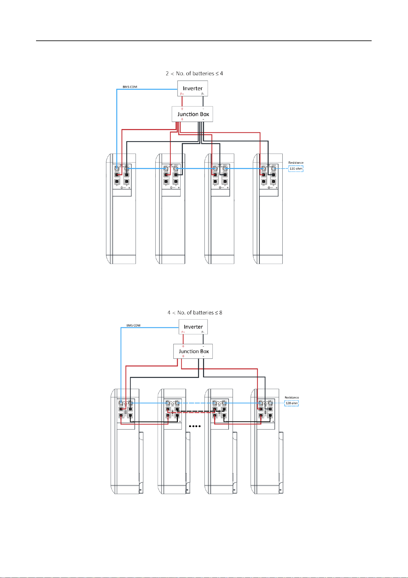
Figure 18. Connect the communication cables (2 < Batteries ≤ 4)
Figure 19. Connect the communication cables (4 < Batteries ≤ 8)

19
2 For the wiring diagram of the inverter to the user side, please refer to the inverter user manual.
Please confirm the usage scenarios of the inverter according to the actual situation. For details, please refer
to the user manual of inverter.
The communication cable to the inverter contains L&N cable (220V power supply for BMS). Please connect
this cable to the output port of the inverter. (Optional)
Recommended open-circuit current from the battery to the inverter: nominal operating current 125A,
nominal operating voltage ≥ DC110V, nominal short-circuit breaking capacity ≥ 15kA (DC110V). If the
inverter has instructions, the inverter shall prevail.
20
3 Operation
3.1 Check before Power-on
Context
After installing the V-POWER S05, users need to perform a pre-power check to ensure that the device
installation and cable connection are correct before performing the power-on operation.
Procedure
1 Check whether the V-Power S05 sequence is consistent with the layout diagram.
2 Check the cable connection on site.
Check whether the cables are connected correctly, whether the connectors are firm, and
whether the self-locking connector is tightly connected.
Check whether the communication cable and the power cable are separated.
3 Check whether the V-Power S05 are grounded.
4 Check the switch status.
The DC output switch of the V-Power S05 should be off.
The DC switch of the inverter should be off.
The circuit breaker from the inverter to the grid should be off.
3.2 Power-on

21
Context
1. Before performing the power-on commissioning on the V-Power S05, users must strictly perform the pre-power-on
check.
2. All batteries should have the 50% factory capacity.
3. Module parallel connection requirements: the total voltage difference between modules should not exceed 2V.
4. Power-on procedure.
1)Vestwoods, Senergy, Megarevo shall activate the inverter first, and then power on the battery module.
2)Deye should power on the battery modules first, and then power on the inverter.
3)For the other inverters, please contact with the technical support engineers.
Prerequisites
Before power on, need ensure that all power cables and communication cables are connected well.
Procedure
Battery power on is divided into three categories.
1 Single battery power on (no parallel connection):
Turn on the DC switch of inverter;
Turn on the switch between the inverter and power grid;
Turn on the circuit breaker between the inverter and battery (if any);
Turn on the ON/OFF switch of battery;
The Run/Alarm indicator should be blinking green.
Waiting for the Run/Alarm indicator lights from green blinking into green, means power on
normally.
2 Multiple batteries power on:
Turn on the DC switch of inverter;
Turn on the switch between the inverter and grid;
Turn on the circuit breaker between the inverter and battery (if any);
First turn on the ON/OFF switch in battery that used for the connect communication with inverter,
at this time the battery Run/Alarm indicator light should be blinking green;
Wait for the battery Run/Alarm indicator lights from green blinking into green normally on;

22
Turn on the ON/OFF switch of the battery that used for connect communication to the next
battery.
Repeat the last step, until the last battery Run/Alarm indicator lights from green blinking into
green, means power on normally.
3 Batteries expand power on:
Power off the original battery and inverter, and connect the newly expanded battery power cable
and communication cable in parallel according to 2.4 and 2.5.
According to the categories 1 or 2, the original battery and inverter to power on first, and make
the original battery capacity is above 50%;
Turn on the ON/OFF switch of one new expansion battery, at this time the battery Run/Alarm
indicator light should be blinking green;
Wait for the battery Run/Alarm indicator lights from green blinking into green normally on;
Turn on the ON/OFF switch of the battery that used for connect communication to the next
battery.
Repeat the last step, until the finally battery Run/Alarm indicator lights from green blinking into
green, means power on normally.
3.3 Operation Guide
V-Power S05 has completed the system parameter settings at the factory, and the system will run
automatically after power is on.
The inverter needs to be set according to actual needs. For detailed operations, please refer to the
inverter User Manual.
23
4 Maintenance
The engineering personnel who perform the following operations must have received professional training. Before
operating and maintaining the V-Power S05, wear anti-static work clothes, anti-static gloves, and wrist straps, and
remove conductive objects such as jewelry and watches to avoid electric shock or burns.
All V-Power S05 internal maintenance work requires insulated tools and should be performed by personnel who
have received relevant training.
When operations such as installation and maintenance only involve the V-Power S05, the output switch of the
V-Power S05 should be kept open. When the inverter is involved, the output switch of the V-Power S05, the DC
switch of the inverter, and the circuit breaker from the inverter to the grid should be kept open.
4.1 V-Power S05 Storage
The recommended storage temperature is 15℃~35℃.
V-Power S05 performance degradation after long-term storage, please shorten shelf time as possible
as you can.
Charge before using to recover capacity loss of self-discharge during storage and transport.
Storage V-Power S05 should be at 40%-50% SOC when it is not used for a long time.
Storage batteries over 40°C or under 0°C will reduce battery life. Store the V-Power S05 in a dry and
low-temperature, well-ventilated place.
If the V-Power S05 is not used for a long time, it must be charged at regular intervals. The charging
requirements are as follows:
Table 9. V-Power S05 Charge Requirement in Storage Status
Storage Temperature
Charge Period
Charge Requirement
20℃~30℃
Every 6 months
1.Charge by 0.2C to 100% SOC
2.Discharge by 0.2C to 0% SOC
3.Charge by 0.2C to 40%~50% SOC
0℃~20℃ or 30℃~40℃
Every 3 months
4.2 Monthly Maintenance
Users should conduct a visual inspection of the V-Power S05 monthly. Please refer to the following table
for monthly maintenance.

24
Table 10. Monthly maintenance
Item
Refer Standard
Abnormal Handling Suggestion
Battery
appearance
The appearance is neat and clean without
stains.
The V-Power S05 terminals are intact.
The V-Power S05 shell is intact, and there are
no bumps, breaks, or cracks around it.
The appearance of battery has no leakage.
There is no deformation or bulging of the shell.
If there is dirt on the surface, clean the
V-Power S05's appearance with a cotton
cloth.
If the appearance is damaged, leaking, or
deformed, take a photo and replace the
defected V-Power S05.
Please contact Vestwoods in time for
other abnormal situations.
Operation
environment
The operation environment is between 0℃-45℃.
Operation humidity range: ≤95% RH.
If temperature and humidity are abnormal,
check the indoor air conditioner status.
4.3 Quarterly Maintenance
Please refer to the following table for the quarterly maintenance of V-Power S05.
Table 11. Quarterly maintenance
Item
Refer Standard
Abnormal Handling Suggestion
Cable
There is no aging of the connecting cable and
no cracking of the insulation layer.
The bolts at the cable connection are not
loose.
Replace the faulty cable.
Fasten the screws.
4.4 Yearly Maintenance
It is recommended to perform trend analysis on recorded data (battery and environment).
4.5 Alarm Handling

25
Table12. Alarm handling
Phenomenon
Possible failure
Handling method
Red light blinking
Cell temperature over low
Check: Ensure that the communication cable between the
inverter and battery is properly connected. View the battery data
on the inverter display or the inverter APP.
If battery temperature ≤ 0℃ while the battery is charging,
the battery under temperature alarm is generated.
If battery temperature ≤ -20℃ while the battery is
discharging, the battery under temperature alarm is
generated.
Alarm recover: When the cell temperature reach to the normal
range,the alarm should be automatically recover.
Red light on
Battery fault
Check: No visual phenomenon.
Alarm recover: Power off the battery system, wait for 5 minutes,
and restart the battery. Check whether the fault can be rectified.
If the fault persists, please contact with the technical support
engineers.

26
Acronyms and Abbreviations
AC Alternating Current
BMS Battery Management System
DC Direct Current
SOC State of Charge