Loading ...
Loading ...
Loading ...
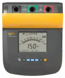
1550C/1555
Users Manual
8
Guard Terminal Use
Note
Insulation resistance is measured between the (+) and (-)
output connections. The Guard terminal (G) is at the same
potential as the negative (-) terminal but is not in the
measurement path.
For most tests, only two test leads are used. Connect the positive (+)
and negative (-) test leads to the corresponding inputs on the Tester.
Connect the test lead probes to the circuit under test. The Guard (G)
terminal is left unconnected.
For the best accuracy when you measure very high resistances, use
three-wire measurements and the Guard terminal. The Guard terminal
is at the same potential as the negative (-) terminal, and can be used
to prevent surface leakage or other unwanted leakage currents from
degrading the accuracy of the insulation resistance measurement.
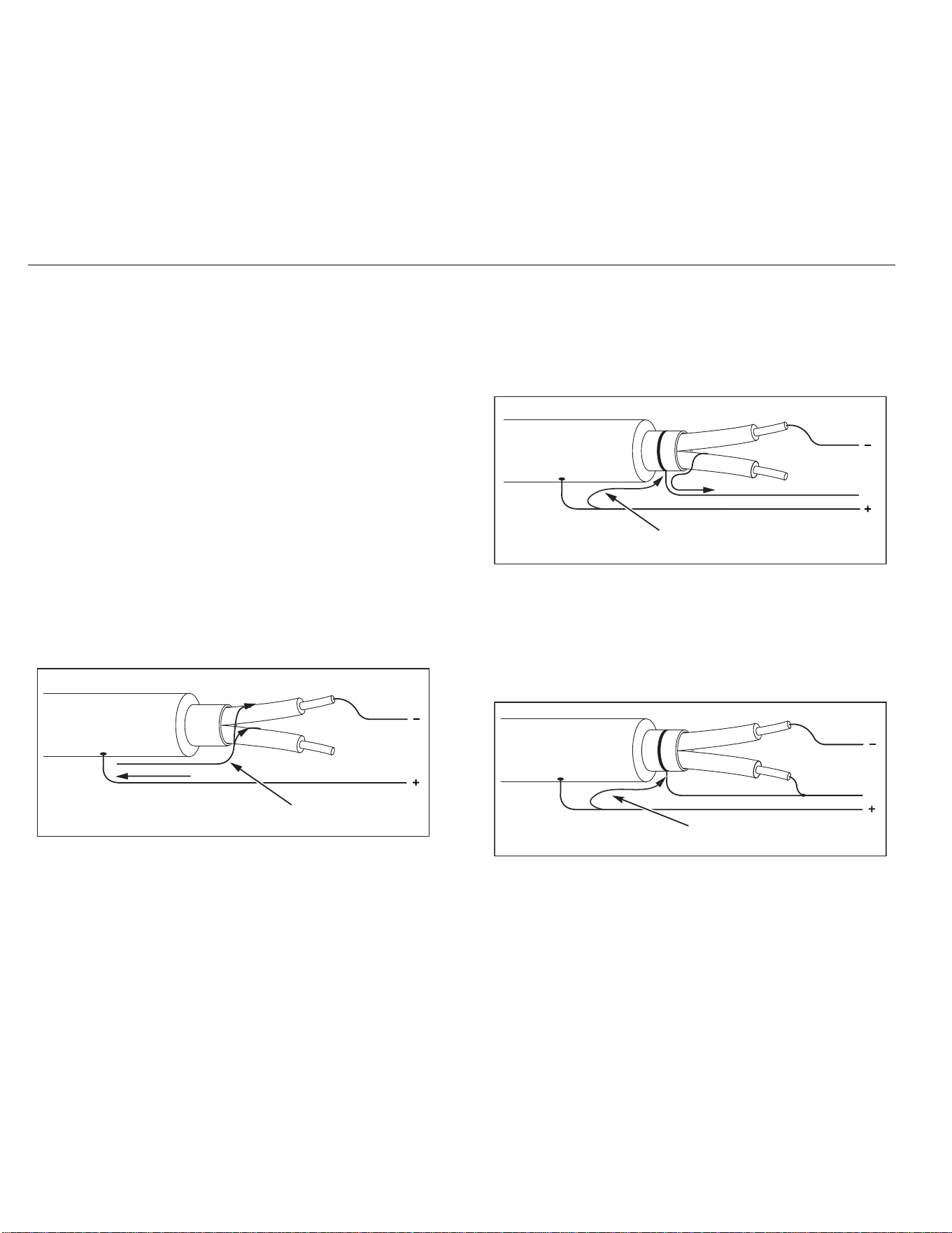
Figure 2 shows how to measure the resistance from one of the
conductors to the outer shield. In this case, there is a leakage current
along the surface of the inner insulation near the cables end. This
leakage adds to the current that the negative terminal senses, and
causes the Tester to read a lower resistance than it should.
Figure 2. Surface Leakage Current
Figure 3 shows how to prevent surface current leakage with a lead
connected from the Guard terminal to a conductor that surrounds the
inner insulation. The surface leakage current is directed to the Guard
terminal. This removes the leakage current from the measurement
path between the positive and negative terminals, and improves the
accuracy of the test readings.
Figure 3. Guard Terminal Connection
Figure 4 shows how to make the measurement setup better. Connect
the Guard terminal to the unused wire and attach it to the inner
insulation. This ensures that the Tester measures the leakage
between the selected conductor and the outer shield, but removes the
leakage path between conductors.
Figure 4. Improved Guard Terminal Connection
Surface Leakage
Current
Shield
( )
( )
Shield
Surface Leakage
Current
Leakage
Current
G
Shield
( )
( )
( )
Optional
Shield
Leakage
Current
Optional
Leakage
Current
G
Shield
( )
( )
( )
Leakage
Current
Shield
1.888.610.7664 sales@GlobalTestSupply.com
Fluke-Direct
.com
Loading ...
Loading ...
Loading ...