
Loading ...
Loading ...
Loading ...
Top View
Chute Rotation
Assembly
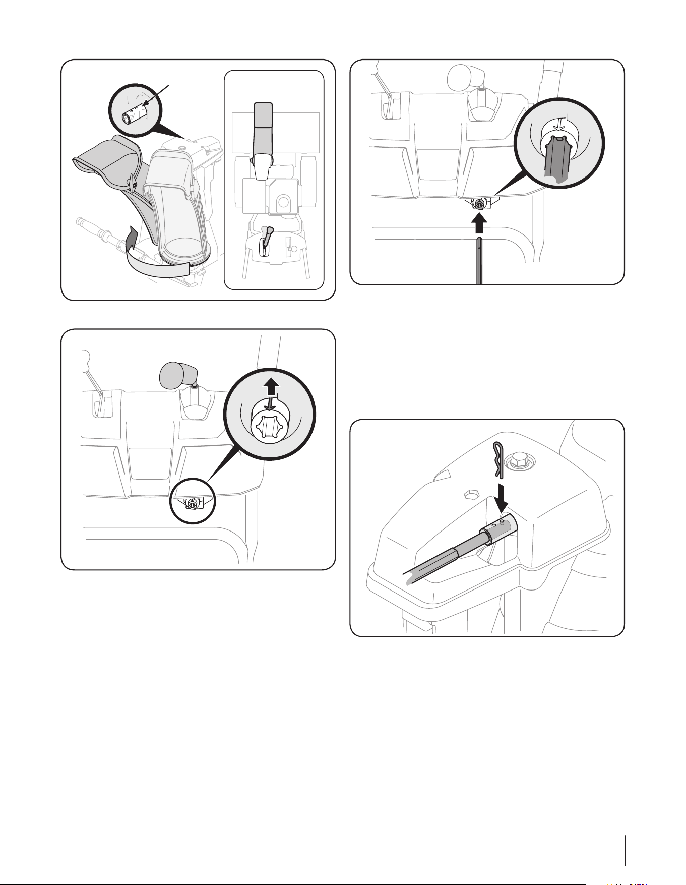
Figure 3-8
Figure 3-9
6. Insert the hex end of the rod (hole pointing upward) into
the pinion gear. See Fig. 3-10.
NOTE: The chute control rod will fit snuggly into the pinion
gear. Support the rear of the dash panel with one hand
while inserting the chute control rod with your other hand
to ensure the chute control rod is inserted all the way into
the pinion gear.
NOTE: The hole is a reference for aligning the rod with the
indicator arrow on the pinion gear, and will be visible after
the rod has been inserted.
Figure 3-10
7. Push the chute control rod toward the control panel until
the hole in the chute control rod lines up with the closest
hole in the chute rotation assembly and insert the cotter
pin. See Fig. 3-11.
NOTE: The second hole is used to achieve further
engagement of the chute control rod into the pinion gear if
required, refer to “Chute Control Rod” in the “Maintenance
and Adjustment” section.
Figure 3-11
8. Finish securing chute rotation assembly to chute support
bracket with wing nut, clevis pin and cotter pin removed
earlier. See Fig. 3-5.
9. It is important that all cables be routed through the cable
guide and remain positioned on the left side of the chute
control rod. See Fig. 3-12.
9Section 3 — ASSembly & Set-Up
Loading ...
Loading ...
Loading ...