
Loading ...
Loading ...
Loading ...
NOTE: Replacement auger shear pins are included with this
manual (or stowed in the plastic handle panel). Refer to Augers in
the Maintainance Section for more information regarding shear
pin replacement.
NOTE: Some models with electric start are equipped with an
extension cord fastened with a cable tie to the rear of the auger
housing for shipping purposes. Cut the cable tie and remove it
before operating the snow thrower.
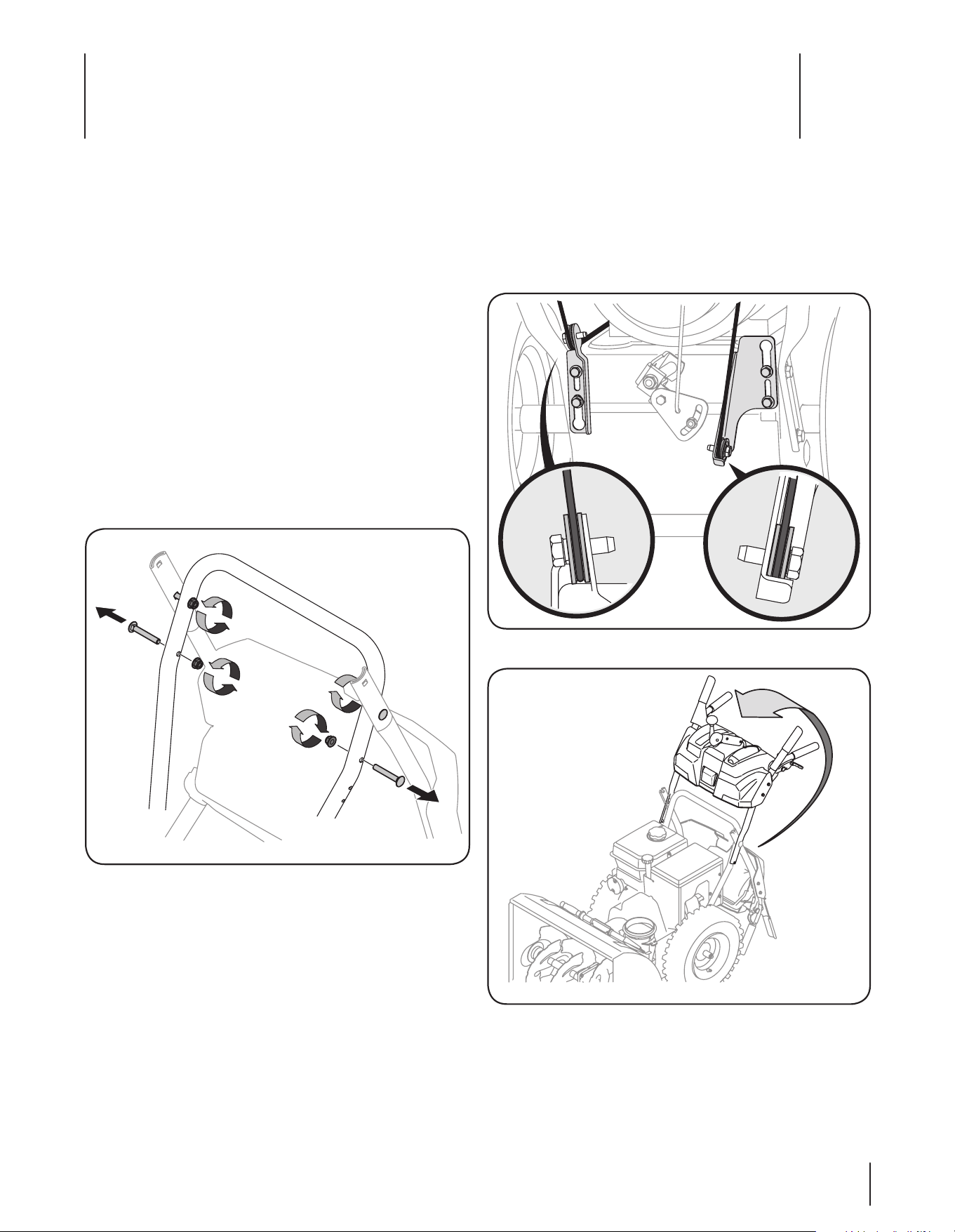
Handle Assembly
• Loosen the top two lock nuts securing the upper and lower
handle and remove the two carriage screws from the lower
handle and set aside as shown in Figure 3-1.
Figure 3-1
• Place the shift lever in the Forward-6 position.
• Observe the lower rear area of the snow thrower to be sure
both cables are aligned with roller guides. See Figure 3-2.
Pull up on the upper handle, align the upper handle with
the lower handle. See Fig. 3-3.
Figure 3-2
Figure 3-3
IMPORTANT: The snow thrower is shipped with oil and WITHOUT GASOLINE. After assembly, refer to separate engine manual for
proper fuel and engine oil recommendations.
NOTE: Remove all loose parts and any packing material before assembling.
NOTE: References to right or left side of the snow thrower are determined from behind the unit in the operating position.
NOTE: This Operator’s Manual covers several models, handle panels, lights and chute cranks are some features that may vary by
model. Not all features referenced (or engines pictured) in this manual are applicable to all snow thrower models.
Assembly & Set-Up
3
7
Loading ...
Loading ...
Loading ...