EN
www.mobotix.com
Innovations– Made in Germany
The German company MOBOTIX AG is known as the leading pioneer in network camera technology and its decentralized concept has made
high-resolution video systems cost-ecient.
MOBOTIX AG • D-67722 Langmeil • Phone: +49 6302 9816-103 • Fax: +49 6302 9816-190 • [email protected]
i25 Quick Install
Security-Vision-Systems
32.086_EN_V1_11/2014
MX-i25
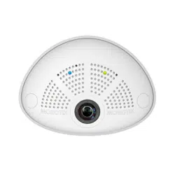
Compact Hemispheric Camera
for Indoor Applications
MOBOTIX 5MP camera for unobtrusive indoor applications,
available as Day or Night version
More information available under www.mobotix.com
> Products>
i25
• Recording on internal microSD card (SDXC)
• Sound recording using integrated microphone
• Speaker available as accessory
• Sensors for temperature, illumination, shock detection integrated
MOBOTIX i25
MX-i25
Camera tilted down-
wards 15 degrees
i25 Standard Delivery
1.2
1.1
1.13
1.14
1.3
1.5
1.6
1.9
1.8
1.12
1.11
1.10
1.7
1.4
Item Count Part Name
1.1 1 Housing (installed)
1.2 1 Back cover (installed)
1.3 1 Main board with lens L12 (installed)
1.4 2 Bayonet catch, blue (installed)
1.5 1 USB plug, blue (installed)
1.6 1 Ethernet plug, blue (installed)
1.7 1 Ethernet patch cable, 50cm/19.7in, black
1.8 1 Wall sealing
1.9 2 Screw plug, white
1.10 2 Washer Ø 4.3mm, stainless steel
1.11 2 Wood screw 4x40mm, stainless steel
1.12 2 Screw anchor S6
1.13 1 MicroSD card (installed)
1.14 1 Allen wrench 2.5mm
Standard Delivery i25 Cavity Wall Installation Set (Accessory)
2.22.1
2.42.3
Item Count Part Name
2.1 1 Mounting plate, stainless steel
2.2 1 Cavity wall socket
2.3 2 Allen screw M3x8mm, stainless steel
2.4 2 Washer Ø 3.2mm, stainless steel
Installation Without Cavity Wall Installation Set
Use the drilling template on the back for this step. Mark the holes for dowels or screws (blue) and the cut-out for the
cables (red). If required, drill the holes for the dowels, push them in and cut the cut-out for the cables. Guide the Ethernet
cable and any other cables that are to be connected through the cut-out.
1. Press wall sealing on i25
Press the wall sealing on the back of the i25
and make sure that it lies flat all around the
rim. Note that the labels of the sealing are
pointing towards the back of the camera.
2. Connect the cables
Insert the cables into the appropriate con-
nectors and fasten them using the blue
bayonet catches.
3. Install the i25
Press the camera and the wall sealing
against the wall and align the holes with
the holes for the dowels or screws. Insert
the screws with washers and tighten them
using a torque of 0.4Nm.
4. Apply screw plugs
Push in the screw plugs to close o the holes
with the screws. When doing so, make sure
that the notches in the plugs follow the guides.
Ethernet
USB
Connection and Initial Operation of the i25
Power/Status
"R" key
Recording
"L" key
For information on connecting the i25, please see the
Q25M Camera Manual,
Section 2.9, «Network and
Power Connection, Additional Cables»
.
Regarding the initial operation of the i25, please see
the Q25M Camera Manual,
Chapter 3, «Initial Operation»
.
Installation With Cavity Wall Installation Set (Accessory)
With this type of installation, the mounting plate of the Cavity Wall Installation Set is screwed onto a cavity wall socket.
The i25 itself is screwed onto the mounting plate using Allen screws. There is no drilling for dowels or screws required.
1.
Cut out the hole for the cavity wall socket
Mark the hole for the cavity wall socket
(green circle on drilling template) and cut
out the hole.
2. Insert the cavity wall socket
Insert the cavity wall socket and tighten the
two screws (red arrows) in order to fasten
the socket in the wall.
3. Remove the screws
Remove the two screws in the cavity wall
socket (red arrows), which are otherwise
used for fastening switches etc.
4. Attach the mounting plate
Use the two screws you just removed to
fasten the mounting plate onto the cavity
wall socket.
5. Press wall sealing on i25
Press the wall sealing onto the back of the
i25 and make sure that it lies flat all around
the rim. Note that the labels of the sealing
are pointing towards the back of the camera.
6. Connect the cables
Guide the cables of the camera from behind
through the cavity wall socket. Insert the Eth-
ernet cable and – if installed– the USB cable
into the corresponding sockets. Secure the
connectors using the blue bayonet catches.
7. Install the i25
Push the remaining cable into the cavity wall
socket, then press the camera and the wall
sealing onto the mounting plate. Use the
two Allen screws with the washers to fasten
the i25 onto the mounting plate (0.4Nm).
8. Apply screw plugs
Push in the screw plugs to close o the holes
with the screws. When doing so, make sure
that the notches in the plugs follow the guides.
Uninstalling the Camera
1. Remove the screw plugs
Remove the two white screw plugs using a
small flat-head screw driver, for example.
2. Remove the retaining screws
Remove the retaining screws using a suit-
able Allen wrench or screwdriver and take
o the entire camera.
Cavity Wall Installation Set (acces-
sory)
Loading ...

