EN
www.mobotix.com
Innovations– Made in Germany
The German company MOBOTIX AG is known as the leading pioneer in network camera technology and its decentralized concept has made
high-resolution video systems cost-ecient.
MOBOTIX AG • D-67722 Langmeil • Phone: +49 6302 9816-103 • Fax: +49 6302 9816-190 • [email protected]
i25 Quick Install
Security-Vision-Systems
32.086_EN_V1_11/2014
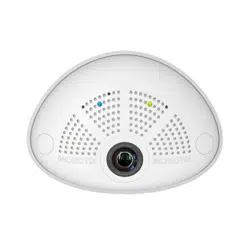
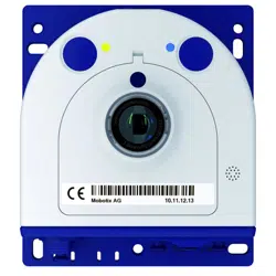
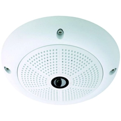
MX-i25
Compact Hemispheric Camera
for Indoor Applications
MOBOTIX 5MP camera for unobtrusive indoor applications,
available as Day or Night version
More information available under www.mobotix.com
> Products>
i25
• Recording on internal microSD card (SDXC)
• Sound recording using integrated microphone
• Speaker available as accessory
• Sensors for temperature, illumination, shock detection integrated
MOBOTIX i25
MX-i25
Camera tilted down-
wards 15 degrees
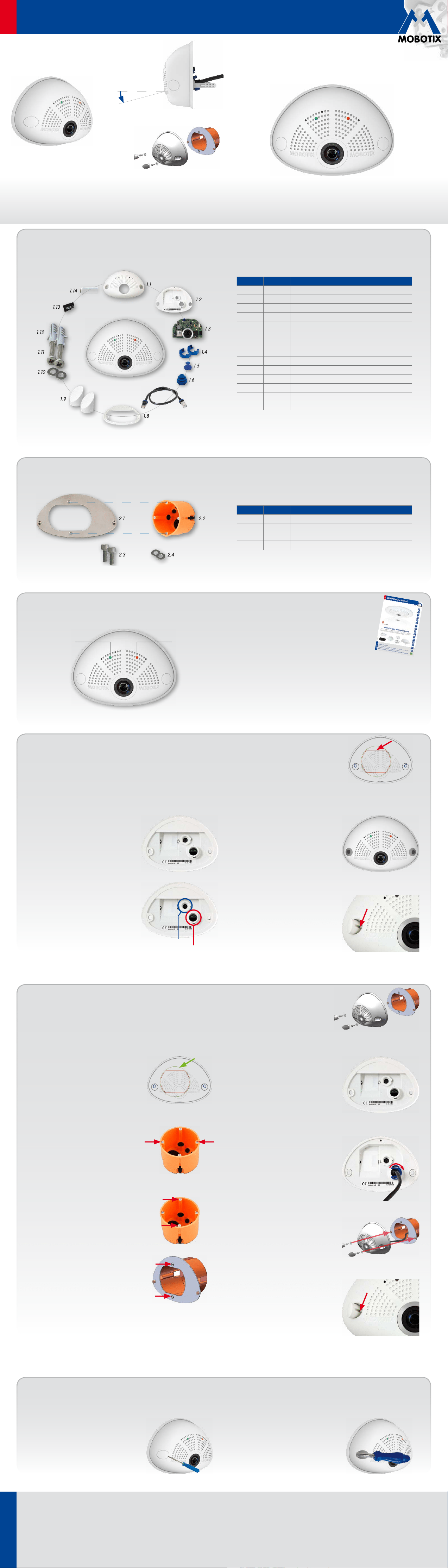
i25 Standard Delivery
1.2
1.1
1.13
1.14
1.3
1.5
1.6
1.9
1.8
1.12
1.11
1.10
1.7
1.4
Item Count Part Name
1.1 1 Housing (installed)
1.2 1 Back cover (installed)
1.3 1 Main board with lens L12 (installed)
1.4 2 Bayonet catch, blue (installed)
1.5 1 USB plug, blue (installed)
1.6 1 Ethernet plug, blue (installed)
1.7 1 Ethernet patch cable, 50cm/19.7in, black
1.8 1 Wall sealing
1.9 2 Screw plug, white
1.10 2 Washer Ø 4.3mm, stainless steel
1.11 2 Wood screw 4x40mm, stainless steel
1.12 2 Screw anchor S6
1.13 1 MicroSD card (installed)
1.14 1 Allen wrench 2.5mm
Standard Delivery i25 Cavity Wall Installation Set (Accessory)
2.22.1
2.42.3
Item Count Part Name
2.1 1 Mounting plate, stainless steel
2.2 1 Cavity wall socket
2.3 2 Allen screw M3x8mm, stainless steel
2.4 2 Washer Ø 3.2mm, stainless steel
Installation Without Cavity Wall Installation Set
Use the drilling template on the back for this step. Mark the holes for dowels or screws (blue) and the cut-out for the
cables (red). If required, drill the holes for the dowels, push them in and cut the cut-out for the cables. Guide the Ethernet
cable and any other cables that are to be connected through the cut-out.
1. Press wall sealing on i25
Press the wall sealing on the back of the i25
and make sure that it lies flat all around the
rim. Note that the labels of the sealing are
pointing towards the back of the camera.
2. Connect the cables
Insert the cables into the appropriate con-
nectors and fasten them using the blue
bayonet catches.
3. Install the i25
Press the camera and the wall sealing
against the wall and align the holes with
the holes for the dowels or screws. Insert
the screws with washers and tighten them
using a torque of 0.4Nm.
4. Apply screw plugs
Push in the screw plugs to close o the holes
with the screws. When doing so, make sure
that the notches in the plugs follow the guides.
Ethernet
USB
Connection and Initial Operation of the i25
Power/Status
"R" key
Recording
"L" key
For information on connecting the i25, please see the
Q25M Camera Manual,
Section 2.9, «Network and
Power Connection, Additional Cables»
.
Regarding the initial operation of the i25, please see
the Q25M Camera Manual,
Chapter 3, «Initial Operation»
.
Installation With Cavity Wall Installation Set (Accessory)
With this type of installation, the mounting plate of the Cavity Wall Installation Set is screwed onto a cavity wall socket.
The i25 itself is screwed onto the mounting plate using Allen screws. There is no drilling for dowels or screws required.
1.
Cut out the hole for the cavity wall socket
Mark the hole for the cavity wall socket
(green circle on drilling template) and cut
out the hole.
2. Insert the cavity wall socket
Insert the cavity wall socket and tighten the
two screws (red arrows) in order to fasten
the socket in the wall.
3. Remove the screws
Remove the two screws in the cavity wall
socket (red arrows), which are otherwise
used for fastening switches etc.
4. Attach the mounting plate
Use the two screws you just removed to
fasten the mounting plate onto the cavity
wall socket.
5. Press wall sealing on i25
Press the wall sealing onto the back of the
i25 and make sure that it lies flat all around
the rim. Note that the labels of the sealing
are pointing towards the back of the camera.
6. Connect the cables
Guide the cables of the camera from behind
through the cavity wall socket. Insert the Eth-
ernet cable and – if installed– the USB cable
into the corresponding sockets. Secure the
connectors using the blue bayonet catches.
7. Install the i25
Push the remaining cable into the cavity wall
socket, then press the camera and the wall
sealing onto the mounting plate. Use the
two Allen screws with the washers to fasten
the i25 onto the mounting plate (0.4Nm).
8. Apply screw plugs
Push in the screw plugs to close o the holes
with the screws. When doing so, make sure
that the notches in the plugs follow the guides.
Uninstalling the Camera
1. Remove the screw plugs
Remove the two white screw plugs using a
small flat-head screw driver, for example.
2. Remove the retaining screws
Remove the retaining screws using a suit-
able Allen wrench or screwdriver and take
o the entire camera.
Cavity Wall Installation Set (acces-
sory)
EN
www.mobotix.com
Innovations– Made in Germany
The German company MOBOTIX AG is known as the leading pioneer in network camera technology and its decentralized concept has made
high-resolution video systems cost-ecient.
MOBOTIX AG • D-67722 Langmeil • Phone: +49 6302 9816-103 • Fax: +49 6302 9816-190 • [email protected]
i25 Quick Install
Security-Vision-Systems
2014 • Declaration of Conformity: www.mobotix.com> Support> MX Media Library> Certificates
Copyright © MOBOTIX AG 2014 • Made in Germany • Technical information subject to change without notice.
Dimensions/Drilling Template
145mm/5.71in
107mm/4.21in
45mm/1.77in
107mm/4.21in
50mm/1.97in
145mm/5.71in
Hole for cables
10mm0.39in
Ø65mm/
2.56in
10mm0.39in
113mm/4.45in
Ø68mm/
2.68in
C
a
v
i
t
y
w
a
l
l
s
o
c
k
e
t
Important Notes
Safety Warnings
• This product must not be used in locations exposed to the dangers
of explosion.
• Make sure that you install this product as outlined in the installation
instructions above.
•
When installing this product, make sure that you are only using genuine
MOBOTIX parts and MOBOTIX connection cables.
• Only install this product on suitable, solid materials that provide for a
sturdy installation of the fixing elements used.
• Electrical systems and equipment may only be installed, modified and
maintained by a qualified electrician or under the direction and supervi-
sion of a qualified electrician in accordance with the applicable electri-
cal guidelines. Make sure to properly set up all electrical connections.
• The power consumption of all attached
MxBus modules
must
not
exceed 2.5W
. When attaching modules to the MxBus connector
and
the USB connector, the
power consumption of all attached modules
must not exceed 1W
.
• Due to the high performance of the i25, the area of the image sensor
can get quite hot, especially when the ambient temperature is also
high. This does not aect the proper functioning of the camera in any
way. This camera must not be installed within the reach of persons.
• Make sure the power supply to the camera is disconnected before
opening the camera housing (e.g., when exchanging the SD card).
• MOBOTIX products include all of the necessary configuration options
for operation in Ethernet networks in compliance with data protection
laws. The operator is responsible for the data protection concept across
the entire system. The basic settings required to prevent misuse can be
configured in the software and are password-protected. This prevents
unauthorized parties from accessing these settings.
•
Make sure that the operating temperature of 0 to +40 °C/+32 to +104 °F
is not exceeded.
Legal Notes
You must comply with all data protection regulations for video and sound
monitoring when using MOBOTIX products. Depending on national laws
and the installation location of the i25, the recording of video and sound
data may be subject to special documentation or it may be prohibited. All
users of MOBOTIX products are therefore required to familiarize themselves
with all valid regulations and comply with these laws. MOBOTIX AG is not
liable for any illegal use of its products.
Technical Specifications
Since the i25 is identical to the Q25M for the most part, the technical data listed in the Q25M Camera Manual in Section
Technical
Data
also applies to this product. You can find the Q25M Camera Manual as a PDF file on www.mobotix.com> Support> Manuals.
i25 (Dierences Compared to Q25M)
Lens Options
L12 (180°)
(horizontal field of view)
Audio features
Microphone is always installed and activated, speaker
depending on variant
Interfaces
Ethernet 10/100, IPv4/IPv6, MiniUSB;
MxBus and inputs/outputs using optional accessory
Power Consumption Typ. 4W
i25 (Dierences Compared to Q25M)
Operating Conditions
IP30 (DIN EN 60529)
0 to +40 °C/+32 to +104 °F (DIN EN 50155)
Dimensions Width 145mm, height 107mm, depth 45mm
Materials Housing: PBT GF30
Weight
approx. 222 g/0.49 lb (incl. 50cm Ethernet patch
cable)
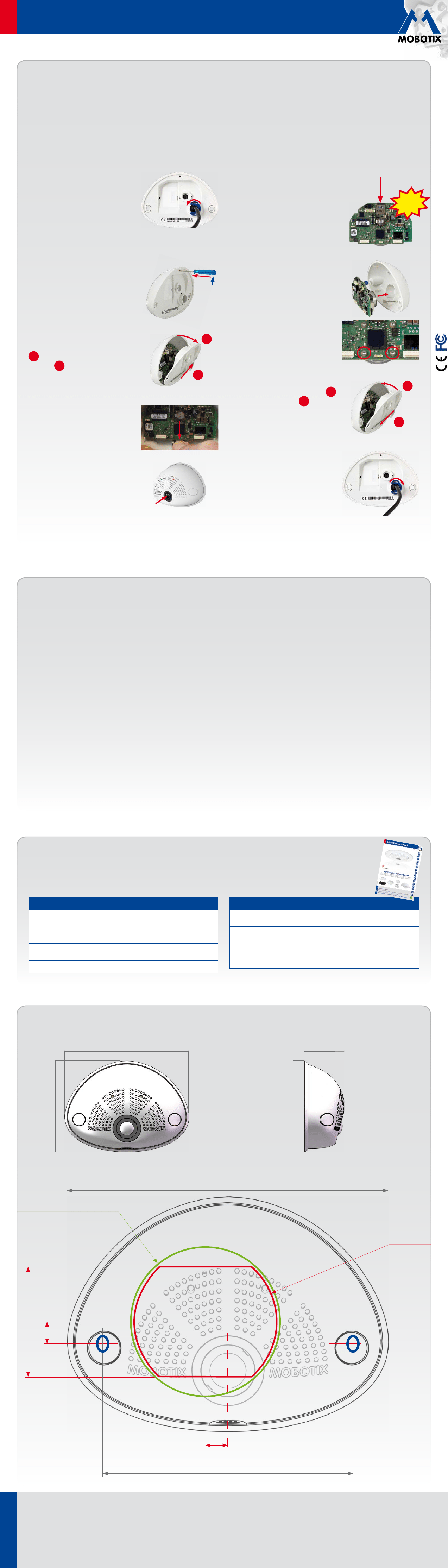
Inserting/Exchanging the SD Card
All camera models can use the integrated microSD card (SDXC) to record video data. In order to exchange the microSD card, please proceed as outlined
in the following instruction. For information on reliable SD cards, please see the MOBOTIX website www.mobotix.com> Support> MX Media Library>
Planning in the document
MicroSD Card Whitelist for MOBOTIX Cameras
. If the camera has already been installed, follow the instructions in section
«Uninstalling the Camera»
.
Caution: In order to avoid damage from electrostatic discharge, you should touch a grounded device before opening the housing of the camera (e.g.,
the blank metal at the back of a computer). This will remove any static electricity that may have built up.
1. Remove the cables on the back
Release the blue bayonet catch, then remove
the patch cable.
If a USB cable is attached, remove this cable
in the same way.
Lay aside the wall sealing of the camera.
2. Remove the back cover
Insert a suitable device into the hole at the
top of the back cover as shown until you
feel resistance.
In order to release the back cover,
cautiously
press upwards as indicated by the blue
arrow. If you are using a flat-head screw-
driver, simply turn the screwdriver.
Gently pull the back cover a bit backwards
1
, then lift the back cover upwards to
remove it
2
.
3. Remove the main board
Release the main board by
gently
pressing
the snap-fit hook beneath the main board
as indicated by the arrow.
Push the main board out of the housing
by gently applying pressure onto the lens
holder (push upwards, since the main board
is tilted downwards 15 degrees).
Take care that the lens holder does not catch
in the tunnel or the snap-fit hook.
4. Remove/insert SD card
If a microSD card has been installed, gently
press with your finger as indicated by the
arrow until you hear a
click
. Then release
the SD card. The card is protruding slightly
and can be easily removed.
Insert the new microSD card and gently
press with your finger as indicated by the
arrow until you hear the
click
.
5. Insert the main board
Insert the lens into the tunnel of the hous-
ing as shown.
Put your thumbs onto the two lower screws
of the main board (red circles) and cautiously
press on the screws until the main board
clicks into place.
6. Insert the back cover
Insert the back cover at the bottom
1
,
then push shut at the top
2
and press
until it clicks into place.
7. Re-connect the cables
Press the wall sealing onto the back of the
i25 and make sure that it lies flat all around
the rim. Note that the labels of the sealing
are pointing towards the back of the camera.
Insert the Ethernet cable and – if installed–
the USB cable into the corresponding sockets
and secure the connectors using the blue
bayonet catches.
1
2
Click!
2
1