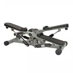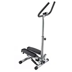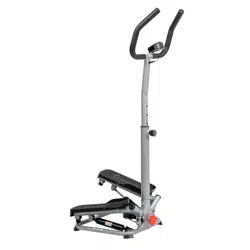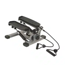
CLIMBER STEPPER WITH
HANDLEBAR
SF-S021001
USER MANUAL
IMPORTANT! Please retain owner’s manual for maintenance and adjustment instructions. Your
satisfaction is very important to us, PLEASE DO NOT RETURN UNTIL YOU HAVE CONTACTED
US: [email protected] or 1- 877 - 90SUNNY (877-907-8669).

1
IMPORTANT SAFETY INFORMATION
We thank you for choosing our product. To ensure your safety and health, please use this
equipment correctly. It is important to read this entire manual before assembling and using the
equipment. Safe and effective use can only be achieved if the equipment is assembled, maintained,
and used properly. It is your responsibility to ensure that all users of the equipment are informed of
all warnings and precautions.
1. Before starting any exercise program, you should consult your physician to determine if you
have any medical or physical condition that could put your health and safety at risk or prevent
you from using the equipment properly. Your physician’s advice is essential if you are taking
medication that affects your heart rate, blood pressure or cholesterol level.
2. Be aware of your body’s signals. Incorrect or excessive exercise can damage your health. Stop
exercising if you experience any of the following symptoms: pain, tightness in your chest,
irregular heartbeat, shortness of breath, lightheadedness, dizziness, or feelings of nausea. If
you do experience any of these conditions, you should consult your physician before continuing
with your exercise program.
3. Keep children and pets away from the equipment. The equipment is designed for adult use
only.
4. Use the equipment on a solid, flat level surface with a protective cover for your floor or carpet.
To ensure safety, the equipment should have at least 2 feet (60 cm) of free space all around it.
5. Ensure that all nuts and bolts are securely tightened before using the equipment. The safety of
the equipment can only be maintained if it is regularly examined for damage and/or wear and
tear.
6. Always use the equipment as indicated. If you find any defective components while assembling
or checking the equipment, or if you hear any unusual noises coming from the equipment
during exercise, discontinue use of the equipment immediately and do not use until the problem
has been rectified.
7. Wear suitable clothing while using the equipment. Avoid wearing loose clothing that may
become entangled in the equipment.
8. Do not place fingers or objects into the moving parts of the equipment.
9. The maximum weight capacity of this unit is 265 lbs (120kgs).
10. The equipment is not suitable for therapeutic use.
11. To avoid bodily injury and/or damage to the product or property, proper lifting and moving are
required.
12. Your product is intended for use in cool and dry conditions. You should avoid storage in
extremely cold, hot or damp areas as this may lead to corrosion and other related problems.
13. This equipment is designed for indoor and home use only; it is not intended for commercial
use.
2
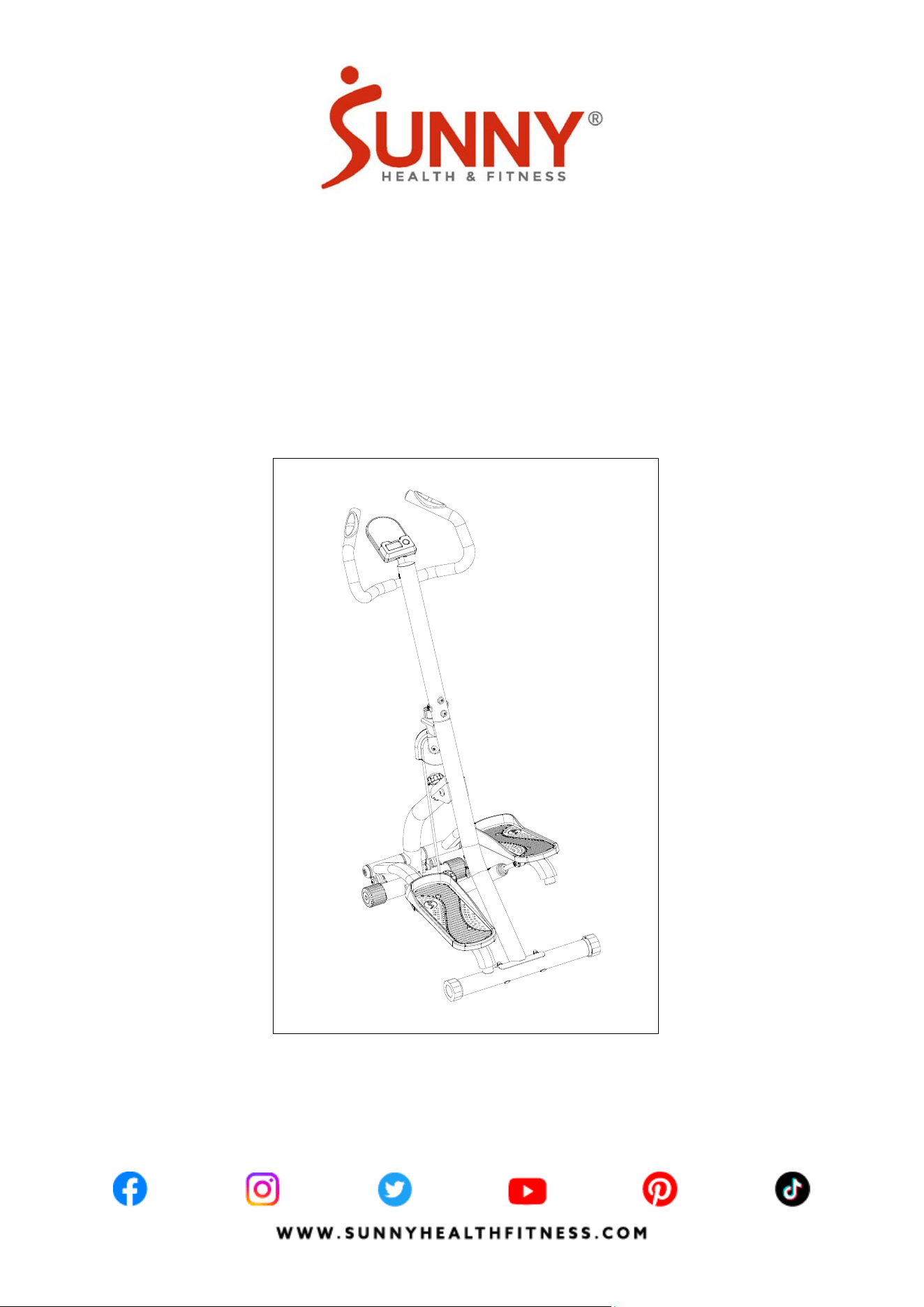
PRE-ASSEMBLY CHECK LIST
Before you start to assemble, please make sure all parts are included.
SF-S021001 HARDWARE PACKAGE
Step 1
Step 2
#63 M8 2PCS
#65 M8*65 2PCS
#31 Φ20 *2.0 2PCS
#30 M 8*16 6PCS
#31 Φ 20*2.0 6PCS
Step 3
#
3
8
M
8
*
4
5
4
P
C
S
#
5
4
Φ
1
6
*
Φ
8
*
1
.
5
4
P
C
S
#
3
7
M
8
4
P
C
S
67 S1 3-1 5-17 1PC
68 S5 1PC
Step 5
#
3
3
M10*50
1
P
C
66
64
3
50
39
UNNY
W W W.S U N N Y H E A L T H F I T N E S S.C O M
IMPORTANT! Please retain owner’s manual for maintenance and adjustment instructions . Your
satisfaction is very important to us, PLEASE DO NOT RETURN UNTIL YOU HAVE CONTACTED
US: support@sunnyhealthfi tness.com or 1-87 7-90SUNNY (877-907 -8669).
CLIMBER S TEPPER WITH
HANDLEBAR
SF-S021001
USER M ANUAL
H E A L T H & F I T N E S S
1
THANK
YOU
FOR YOUR PURCHASE
UNNY
No. Description Spec. Qty. No. Description Spec. Qty.
1 Rear Support Tube
1
66 Handlebar
1
3 Handlebar Post 1
A
Hardware Package 1
7 Computer BJHT-087 1 B Thank You Card
1
39 Left Pedal 354*140*46 1
C
Manual 1
50 Right Pedal 354*140*46 1
D
Battery 1.5V AAA
2
64 Rear Stabilizer 138*138*94 1
Ordering Replacement Parts (U.S. and Canadian Customers only)
Please provide the following information in order for us to accurately identify the part(s) needed:
The model number (found on cover of manual)
The product name (found on cover of manual)
The part number found on the “EXPLODED DIAGRAM” (page 12) and “PARTS LIST” (page 13)
Please contact us at support@sunnyhealthfitness.com or 1- 877 - 90SUNNY (877-907-8669).
3
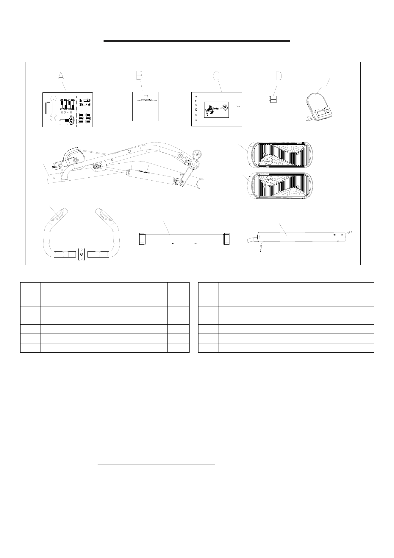
HARDWARE PACKAGE
Step 5
#
3
3
M10*50
1
P
C
#67 S13-15-17 1PC
#68 S5 1PC
Step 1
Step 2
#63 M8 2PCS
#65 M8*65 2PCS
#31 Φ20*2.0 2PCS
#30 M8*16 6PCS
#31 Φ20*2.0 6PCS
Step 3
#
3
8
M
8
*
4
5
4
P
C
S
#
5
4
Φ
1
6
*
Φ
8
*
1
.
5
4
P
C
S
#
3
7
M
8
4
P
C
S
SF-S021001 HARDWARE PACKAGE
4
ASSEMBLY INSTRUCTIONS
We value your experience using Sunny Health and Fitness products. For assistance with parts or
troubleshooting, please contact us at support@sunnyhealthfitness.com or 1-877-90SUNNY
(877-907-8669).
#65 M8*65 2PCS
#31 Φ20*2.0 2PCS
#63 M8 2PCS
#67 S13-15-17 1PC
#31 Φ20*2.0 6PCS
#30 M8*16 6PCS
#68 S5 1PC
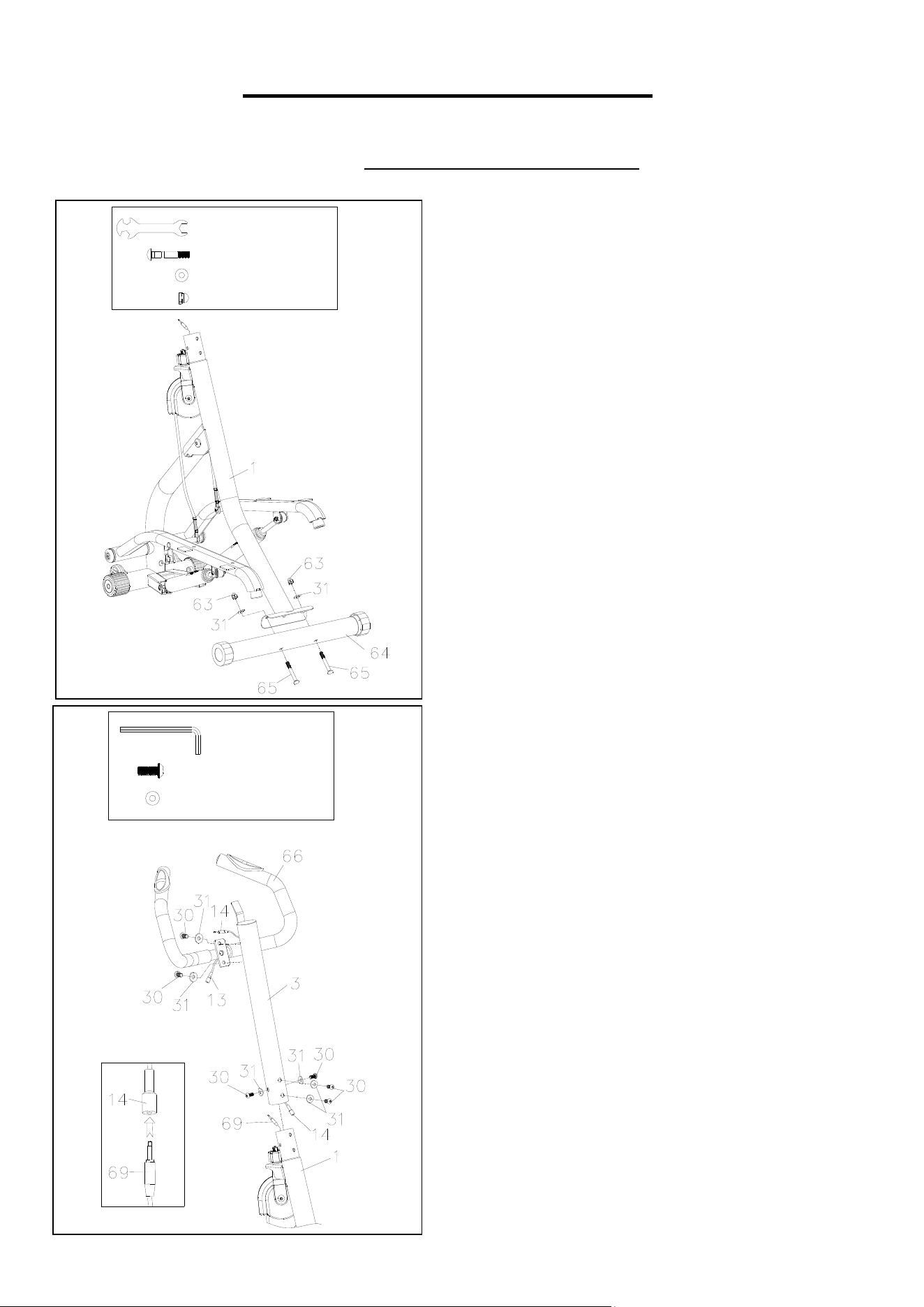
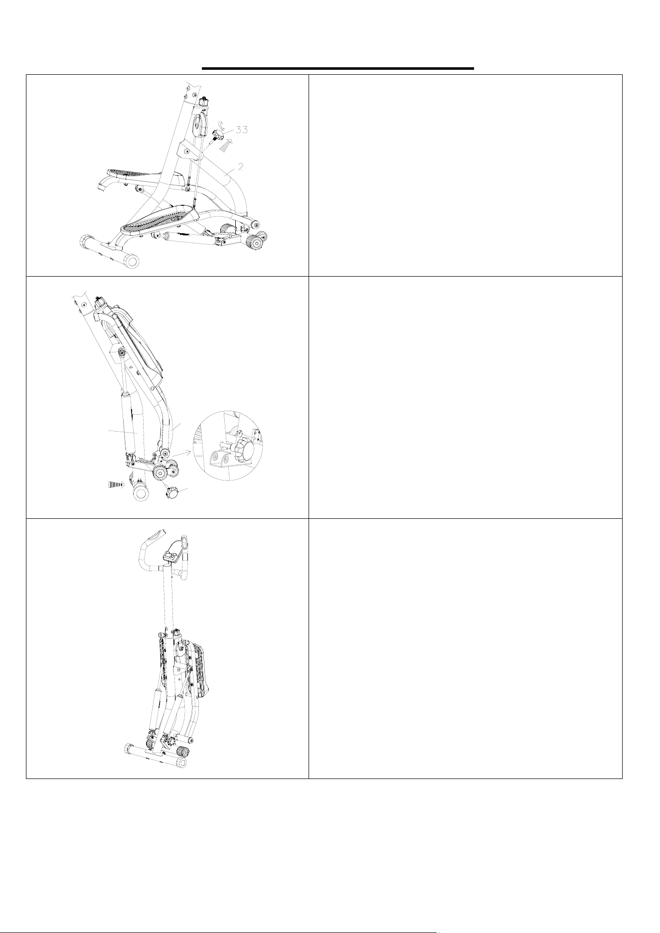
STEP 1:
Remove the Rear Support Tube (No. 1) from
the box. Open the Rear Support Tube (No. 1)
as shown in the picture on the left.
Attach the Rear Stabilizer (No. 64) to the Rear
Support Tube (No. 1) using 2 Bolts (No. 65), 2
Cap Nuts (No. 63) and 2 Arc Washers (No. 31).
Tighten and secure with the Spanner (No. 67).
STEP 2:
Connect the lower end of the Sensor Wire (No.
14) with the Extension Wire (No. 69).
Insert the Handlebar Post (No. 3) into the Rear
Support Tube (No. 1) with 4 Hexagon Bolts
(No. 30) and 4 Arc Washers (No. 31). Tighten
and secure with the Allen Wrench (No. 68).
Attach the Handlebar (No. 66) onto the
Handlebar Post (No. 3) with 2 Hexagon Bolts
(No. 30) and 2 Arc Washers (No. 31). Tighten
and secure with the Allen Wrench (No. 68).
5
We value your experience using Sunny Health and Fitness products. For assistance with parts or
troubleshooting, please contact us at support@sunnyhealthfitness.com or 1-877-90SUNNY
(877-907-8669).
#67 S13-15-17 1PC
#38 M8*45 4PCS
#54 Φ16*Φ8*1.5 4PCS
#37 M8 4PCS
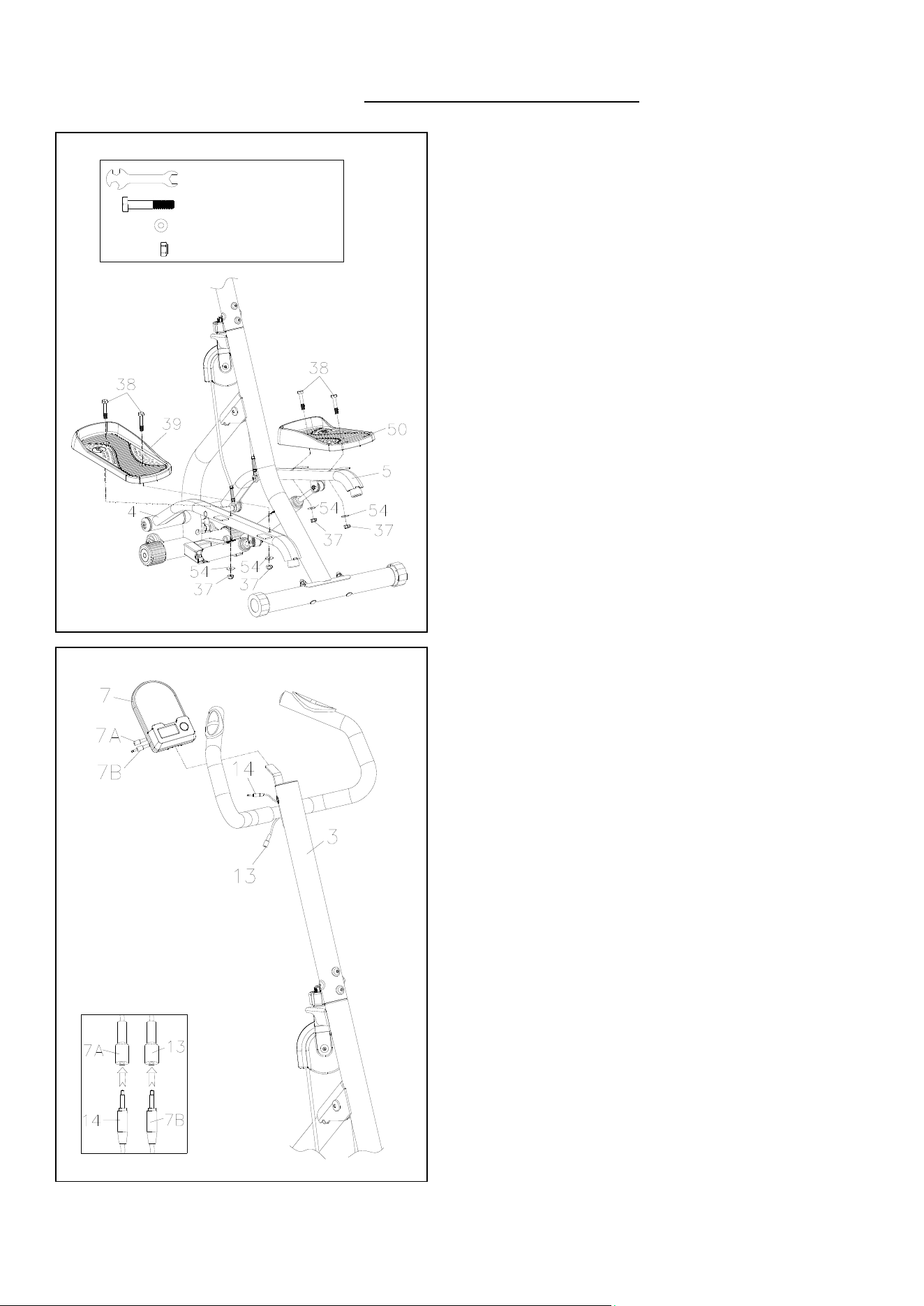
STEP 3:
Attach the Left Pedal (No. 39) onto the Left
Pedal Bar (No. 4) with 2 Nuts (No. 37), 2
Hexagon Bolts (No.38) and 2 Flat Washers
(No.54). Tighten and secure with the Spanner
(No. 67).
Attach the Right Pedal (No. 50) onto the Right
Pedal Bar (No. 5) with 2 Nuts (No. 37), 2
Hexagon Bolts (No.38) and 2 Flat Washers
(No.54). Tighten and secure with the Spanner
(No. 67).
STEP 4:
Connect the Computer Wire A (No. 7A) with the
Sensor Wire (No. 14).
Connect the Computer Wire B (No. 7B) with the
Pulse Wire (No. 13).
Insert the Computer (No. 7) onto the tab on the
Handlebar Post (No. 3).
6
We value your experience using Sunny Health and Fitness products. For assistance with parts or
troubleshooting, please contact us at support@sunnyhealthfitness.com or 1-877-90SUNNY
(877-907-8669).
#
3
3
M10*50
1
P
C
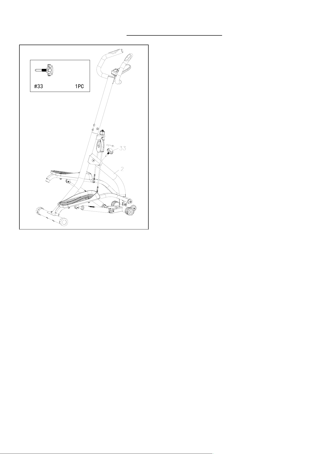
STEP 5:
Take out the Adjustment Knob (No. 33) from
the hardware package.
Then insert the Adjustment Knob (No. 33) into
the Front Support Tube (No. 2) and adjust the
tightness of the Adjustment Knob (No. 33) to
the desired position.
The assembly is complete
!
7
MAINTENANCE & ADJUSTMENT GUIDE
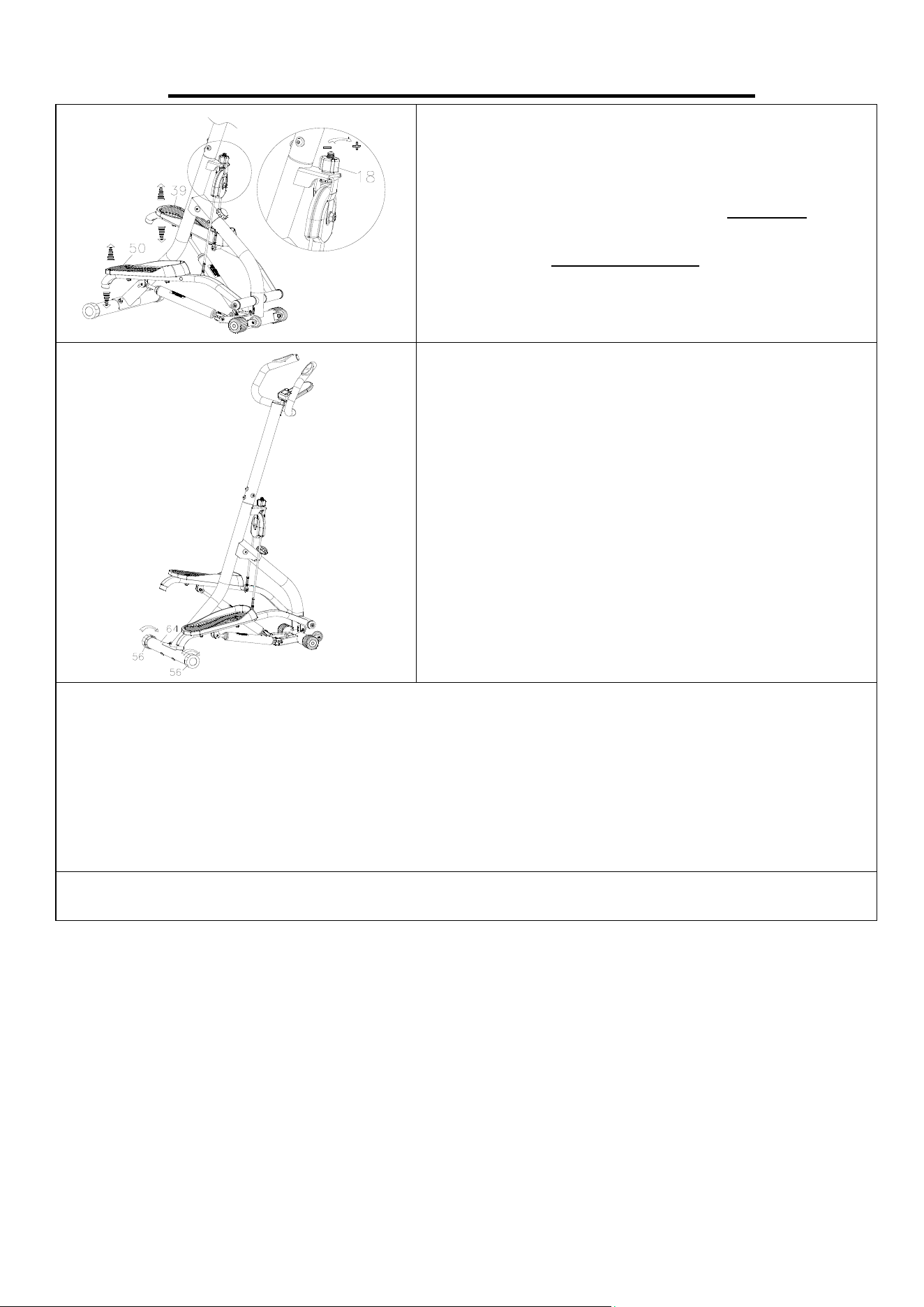
ADJUSTING THE PEDAL STEPPING HEIGHT
Before adjusting the stepping height, raise the Left
Pedal (No. 39) or Right Pedal (No. 50) first. Then
turn the Adjustment Knob (No. 18) clockwise to
increase the stepping height. Turn the Adjustment
Knob (No. 18) counter-clockwise to decrease the
stepping height.
ADJUSTING THE BALANCE
To achieve a smooth and comfortable use, you must
ensure that the stepper is stable and secured. If you
notice the stepper is unbalanced during use, adjust
the Adjustable Plug (No. 56) located on the Rear
Stabilizer (No. 64) until the stepper becomes levelled
with the floor surface.
CLEANING
The stepper can be cleaned with a soft, clean, and damp cloth. Do not use abrasives or solvents
on plastic parts. Please wipe your perspiration off the stepper after each use. Be careful not to get
excessive moisture on the computer display panel as this might cause electrical hazards or
electronics failure.
Please keep the stepper, especially the computer, out of direct sunlight to prevent screen damage.
Please inspect all assembly bolts and pedals on the stepper for proper tightness every week.
STORAGE
Store the stepper in a clean and dry environment, away from children.
NOTES:
The Hydraulic Cylinder (NO. 60) may become excessively hot after prolonged use and may be
dangerous to touch. Allow the Hydraulic Cylinder (NO. 60) to cool between uses.
8
FOLDING INSTRUCTIONS
A. Remove the Adjustment Knob (No. 33) from
the Front Support Tube (No. 2).
2
1
33
B. Bring the Rear Support Tube (No. 1) and the
Front Support Tube (No. 2) closer to each
other. Insert the Adjustment Knob (No. 33)
into the hole on the Rear Support Tube (No. 1),
tighten and secure with your hand.
C. The folding is complete!
9
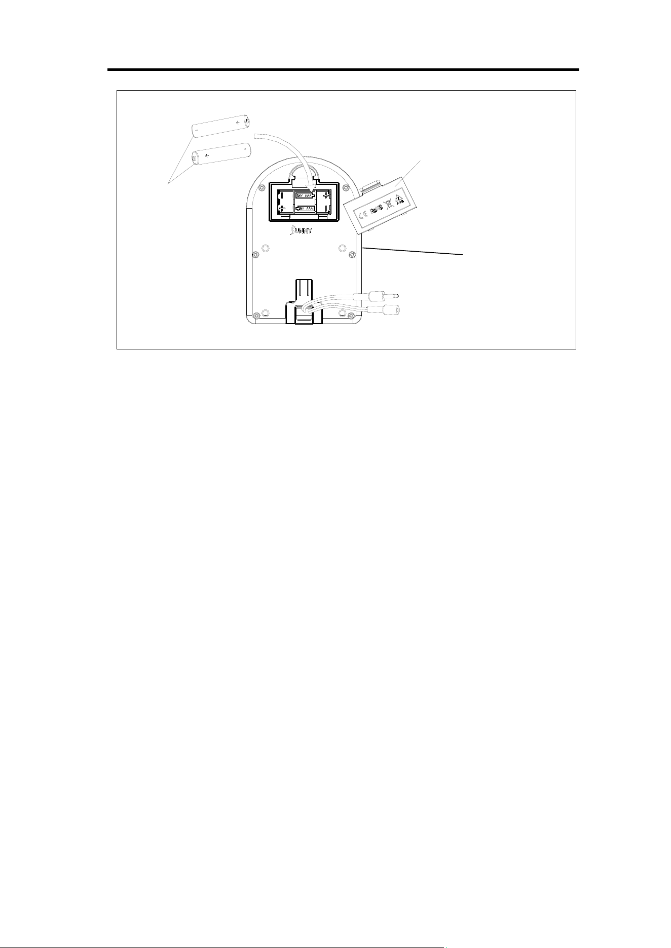
BATTERY INSTALLATION & REPLACEMENT
BATTERY INSTALLATION:
1. Take out 2 AAA batteries from computer box.
2. Press the buckle of battery cover on the back of the Computer (No. 7), then remove battery
cover.
3. Install 2 AAA batteries into the battery case on the back of the Computer (No. 7). Pay attention
to the battery + and – ends before installing.
4. Press the buckle of battery cover, then put the battery cover back to the back of the Computer
(No. 7).
The installation is complete!
BATTERY REPLACEMENT:
1. Press the buckle of battery cover on the back of the Computer (No. 7), then remove battery
cover.
2. Remove the 2 old AAA batteries in the battery case and install 2 new AAA batteries into the
battery case on the back of the Computer (No. 7). Pay attention to the battery + and – ends
before installing.
3. Press the buckle of battery cover, then put the battery cover back to the back of the Computer
(No. 7).
The replacement is complete!
BATTERY DISPOSAL
NOTE: Always change both batteries at the same time. Do not mix battery types and do not mix old
and new batteries. Dispose batteries according to your state and regional guidelines.
Battery Cover
Battery
7
10
EXERCISE COMPUTER
HEALTH & FITNESS
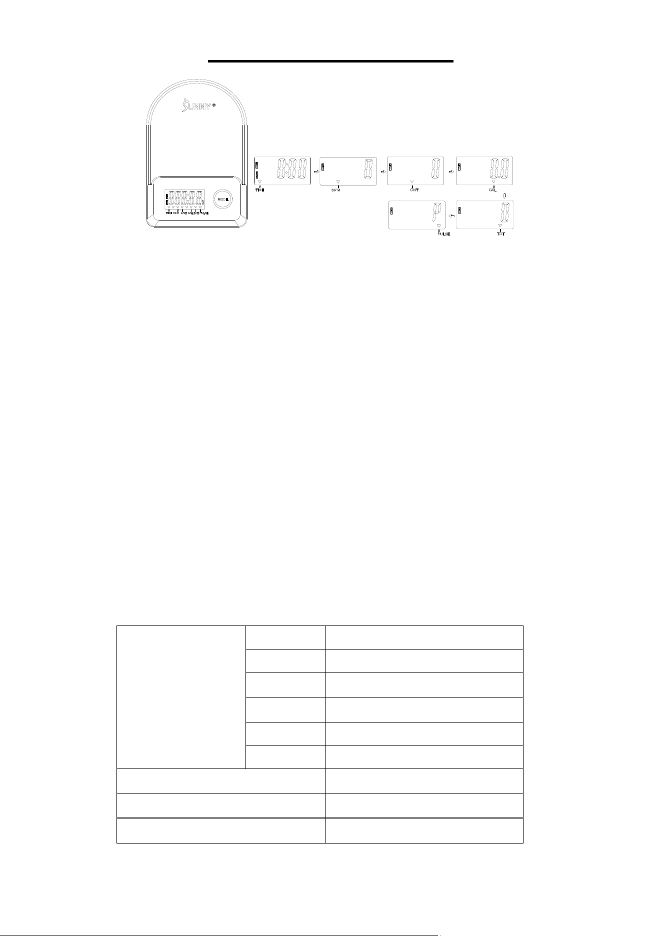
KEY FUNCTIONS:
Pressing the MODE key to select and lock on a function for following sequence:
TIME SPM CNTCALTOTPULSE.
Pressing and holding the MODE key for 3 seconds to reset the value to zero (without TOT).
SLEEP MODE:
The system turns on when the MODE key is pressed or system senses a signal input from the
sensor.
The system turns off automatically when the sensor has no signal input or no key is pressed for
approximately 4 minutes.
FUNCTIONS:
TIME: The total working times with starting exercise.
SPM: Number of strokes per minute, indicating the stroke speed during exercise.
CNT: The current count with starting exercise.
CAL: The calories burned with starting exercise.
TOT: The total count which this function refers to from battery capacity period runs.
PULSE: The current pulse rate with starting exercise.
SPECIFICATIONS:
FUNCTION
TIME
999:59M:S
SPM 0~199
CNT 0~99999
CAL 0.0~9999.9
TOT 0~99999
PULSE 40-240BPM
BATTERY SIZE-AAA *2
Operating temperature
0~40℃(32℉-104℉)
Storage temperature
-10~60℃(14℉-140℉)

11
APP CONNECTION:
Connect Smart Equipment to SunnyFit App:
1. Scan to download SunnyFit from the app store:
2. Ensure that the Bluetooth function is turned on from your mobile device.
3. If this is your first time using the SunnyFit app, follow the in-app instructions to register for your
free SunnyFit account and log in.
4. Begin any workout activity that matches your smart equipment, then follow the onscreen
prompts to search for and connect to your smart equipment.
5. When connected, your stats and records will be displayed at the end of your course/session,
and recorded in your account profile!
Troubleshooting:
If you are having trouble connecting your smart equipment, visit www.sunnyfit.com/guide or
scan the QR code below:
If you require additional support, please contact support@sunnyfit.com
12
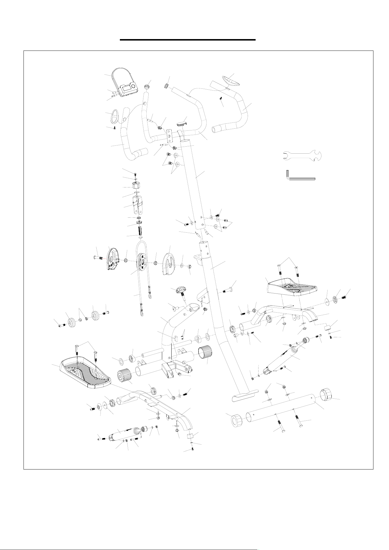
EXPLODED DIAGRAM
1
2
3
4
5
6
12
16
17
18
20
21
22
23
24
25
25
24
26
27
28
29
30
31
31
31
30
30
33
32
34
35
36
35
37
36
38
39
40
38
41
42
42
44
43
45
45
37
37
37
41
40
46
47
48
49
50
51
52
53
46
49
48
16
16
53
52
51
17
17
46
46
54
54
37
54
54
55
55
56
56
57
58
59
60
59
57
58
59
59
58
57
57
58
60
7
8
9
10
11
8
9
10
11
15
13
14
30
31
31
63
31
65
65
64
19
61
62
66
15
14
69
67
68
70
70
7A
7B

13
PARTS LIST
No. Description Spec. Qty.
No. Description Spec. Qty.
1 Rear Support Tube 1 35 Hexagon Bolt M8*35*S5 2
2 Front Support Tube 1 36 Roller Φ50*Φ8.6*20.5 2
3 Handlebar Post 1 37 Nut M8 6
4 Left Pedal Bar 1 38 Hexagon Bolt M8*45 4
5 Right Pedal Bar 1 39 Left Pedal 354*140*46 1
6 U-shaped Bracket 1 40 Flat Washer Φ38*Φ19.1*1.0 2
7 Computer BJHT-087 1 41 Spacer Φ38*Φ19.1 2
7A Computer Wire A 1 42 End Cap Φ50*1.5 2
7B Computer Wire B 1 43 Sensor Base 1
8 End Cap Φ25*1.5 2 44 Screw ST3.2*10 2
9 Grip Piece 2 45 Grommet Φ14.5*Φ12.2*Φ3.0 2
10 Screw ST4.2*19 2 46 Bushing Φ38*Φ19.1*12 4
11 Foam Grip Φ32*Φ24*460 2 47 Magnet 1
12
Handle Post End
Φ50*1.5 1 48 Hexagon Bolt M6*20*S5 2
13 Pulse Wire L500 1 49 Flat Washer D6*Φ18*2.0 2
14 Sensor Wire L500 1 50 Right Pedal 354*140*46 1
15 Grommet Φ14.5*Φ12*Φ4.0 2 51 Flat Washer D8*Φ38*2 2
16 Hexagon Bolt M5*10*S3 3 52 Cover Φ38*Φ8.2*7.5 2
17 Flat Washer D5.5*Φ12.5*1.0 3 53 Hexagon Bolt M8*20*S5 2
18 Adjustment Knob Φ38*29*M12 1 54 Flat Washer Φ16*Φ8*1.5 4
19 Flat Washer D13*Φ24*2.5 1 55 Cushion Φ30*20 2
20 Powder Metallurgy Φ19*Φ16*Φ12*6 1 56 Adjustable Plug Φ50 2
21 Bearing Φ26*Φ12*9 1 57 Nut M6 4
22 Hexagon Bolt M12*M5*60 1 58 Flat Washer D6*Φ12*1.2 4
23 Hexagon Bolt M10*45*15*S6 1 59 Hexagon Bolt M6*36*8*S4 4
24 Pulley Guard 119*114*19.5 2 60 Hydraulic Cylinder Φ38 2
25 Powder Metallurgy Φ21*Φ10*8 2 61 Magnet Cover Φ15*Φ3*3.5 1
26 Flat Washer D10*Φ22*2.0 1 62 Screw ST3*8 1
27 Nut M10 1 63 Cap Nut M8 2
28 Pulley Φ102.5*28 1 64 Rear Stabilizer 138*138*94 1
29 Wire Rope Φ6.5*795 1 65 Bolt M8*65 2
30 Hexagon Bolt M8*16 6 66 Handlebar 1
31 Arc Washer Φ20*2.0 8 67 Spanner S13-15-17 1
32 Bolt Φ12*22.5*M8 1 68 Allen Wrench S5 1
33 Adjustment Knob M10*50 1 69 Extension Wire 1
34 Bolt Φ12*32*M8 1 70 Powder Metallurgy Φ17*Φ10.1*6.5 2
Version: 1.3

14