

Commercial Pro Land Management System
5
0” Snow Plow Attachment
STARTING SERIAL # L120-001001
SWISHER ACQUISITION INC.
1602 Corporate Drive, Warrensburg Missouri 64093
Phone: 660-747-8183 FAX: 660-747-8650
Toll Free: 1-800-222-8183
Manufacturing quality lawn care equipment since 1945,
Celebrating over 75 years of innovation
22066 REV 20-001
Model #: VSP50
Safety S
et Up Maintenance Operation Parts Warranty
OWNER’S MANUAL
For use with model VT389H Versa Walk
Behind Tractor (sold separately).
Plow is also compatible with these other
Swisher Universal Plow Mount Kits:
2646 (ATV)
20096 (UTV)
10260 (ATV/UTV Front Hitch Receiver)
6/25/2020

INTRODUCTION 3
S
AFETY 4 - 6
DECALS 6
FEATURES, LOCATION 7
SPECIFICATIONS 7
UNCRATING & ASSEMBLY 8
CONNECTING AND DISCONNECT ATTACHMENT 9
CUSTOMER RESPONSIBILITY 10
OPERATOR PRESENCE SYSTEM 10
TRANSPORTING 10
MAINTENANCE SCHEDULE 10
OPERATION 10 - 13
STARTING 10
PLOW HEIGHT CONTROLS 11
TILT SPRING TENSIONING 11
PLOW TILT ADJUSTMENT 11
PLOW ANGLE ADJUSTMENT 12
SKID SHOE ADJUSTMENT 13
PLOW OPERATING TIPS AND INSTRUCTIONS 13
PARTS IDENTIFICATION 14 - 15
PLOW 14
PLOW MOUNT 15
PRODUCT IDENTIFICATION 16
CUSTOMER NOTES 17
TORQUE REFERENCE GUIDE 18
LIMITED WARRANTY 19
ACCESSORIES 20
SWISHER HISTORY 21
TABLE OF CONTENTS
2

蘀
Ң
Congratulations!
T
hank you for purchasing Swisher’s Versa Snow Plow Attachment! The VSP50 Snow
Plow is our Versa Land Management Systems latest addition for the VT389 Versa Tractor.
This manual is a valuable document. Following the instructions for use, service, maintenance, etc. can
greatly increase the performance and life of your machine.
General:
IMPORTANT!
In
this operator’s manual, left and right, backward and forward are used in relation to the normal operator’s
position on the tractor.
FIGURE
references used throughout reflect the page number as the first number (e.g. FIG. 20.1 is on page 20, FIG. 15.2 is on
page 15, etc.)
Read Before Operating:
This attachment is constructed for plowing snow. The manufacturer’s directions concerning operation, maintenance and
repairs must be carefully followed.
This machine must only be operated, maintained and repaired by persons who are familiar with the machine’s special
characteristics and who are well versed in safety instructions.
Accident prevention regulations, other general safety regulations, occupational safety rules and traffic regulations must be
followed without fail.
Unauthorized modifications to the design of the machine may absolve the manufacturer from liability for any resulting
personal injury or property damage and may void the warranty.
Read and observe all safety instructions represented on decals and in the manual.
Refer to your VT389H tractor manual for the following instructions:
Kn
ow how to set the parking brake – Push down on brake lever with foot until it locks in place.
Know how to stop the engine – Turn key to off or flip shut off switch down.
Know how to stop the unit – Return control handles to neutral.
WARNING: B
e sure all users have read and understand the Operators Manual for
the VT389H tractor before attempting to operate.
DANGER: Indicates an IMMINENTLY HAZARDOUS SITUATION! If not avoided, WILL result in death
or serious injury.
WARNING: Indicates a POTENTIALLY HAZARDOUS SITUATION! If not avoided, COULD
result in death or serious injury.
CAUTION: Indicates a POTENTIALLY HAZARDOUS SITUATION! If not avoided, MAY result in
minor or moderate injury. It may also be used to alert against unsafe practices.
THIS SAFETY ALERT SYMBOL IDENTIFIES AN IMPORTANT SAFE
TY MESSAGE IN THIS
MANUAL THAT HELPS YOU AND OTHERS AVOID PERSONAL INJUR
Y OR EVEN
DEATH. DANGER, WARNING, AND CAUTION ARE SIGNAL WORDS USED TO
IDENTIFY THE LEVEL OF HAZARD. HOWEVER, REGARDLESS OF THE HAZARD, BE
EXTREMELY CAREFUL.
INTRODUCTION
3

児
ҥ
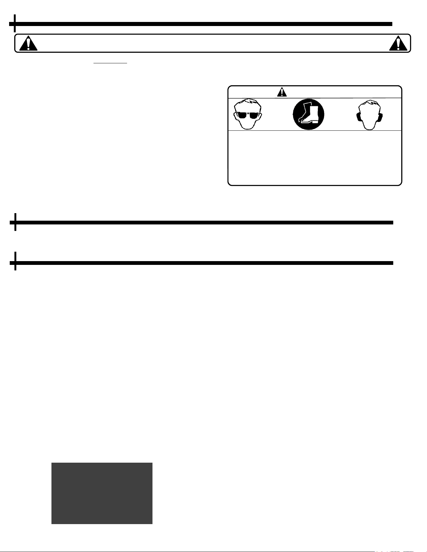
These instructions a
re for your safety. Read them thoroughly & carefully.
This Safety Alert Symbol indicates important messages in this manual. When you
see this symbol, carefully read the message that follows and be alert to the
possibility of personal injury.
Remember: The operator is responsible for
avoiding dangers or accidents.
Always make sure long hair is not left down when
servicing and/or operating the machine. Make sure hair
is out of the way of any moving parts or pinch points.
Inspect the attachment and tractor before each use.
Make sure all hardware is in place and tightened
properly.
Make sure this attachment is in good operating
condition and properly connected and secured.
Never use the machine when barefoot. Always wear
protective shoes or boots.
Always wear protective glasses or full visor and hearing
protection when assembling or operating.
Never wear loose clothing that can get caught in
moving parts.
Check that any safety or informational decals are in
place and legible. Replace any damaged decals.
Slope Operation:
I
nspect the area and remove obstacles such as stones,
tree branches, etc.
With walk behind machines, operate across slopes, not
up and down.
Never drive the machine on terrain that slopes more
than 15 degrees.
Avoid starting or stopping on a slope. If the tires begin
to slip, drive slowly straight down the slope.
Always drive evenly and slowly on slopes.
Do not make sudden changes in speed or direction.
Avoid unnecessary turns on slopes. If it becomes
necessary, turn slowly and gradually downward if
possible.
Watch for holes, ruts or bumps. On uneven terrain, the
machine can tip more easily. Deep snow or other debris
can hide obstacles.
Drive slowly and use small movements of the steering
controls.
Do not plow snow or ice covered slopes. It is slippery,
and the tires can lose their traction, allowing the
machine to slide down the slope.
Safety instructions continue on next page….
General Use:
R
ead all instructions in this operator’s manual and on
the machine before starting it. Ensure that you
understand them and then abide by them. Be prepared
to stop the engine quickly in an emergency.
Learn how to use the machine, operate its controls
safely, how to stop quickly and recognize safety decals.
Only allow the machine to be used by adults who are
familiar with its use and operation. If there are any
questions about safety do not operate or allow others
to operate this machine.
Make sure nobody else is in the area of the machine
when you start the engine, engage the drive or operate
the machine.
Stop the machine if someone enters the work area.
Clear the area of any objects such as stones, toys, etc.
that may be struck by the plow.
DO NOT use this machine without the Guards or Belt
Covers in place.
St
op the engine and disconnect the spark plug before
performing maintenance checks.
Never attempt to inspect the PTO shaft with the engine
running and always remove the ignition key and spark
plug wires before clearing debris.
Never take passengers. The machine is only intended
for use by one person.
Always look around before and during reversing
maneuvers.
Slow down before turning.
Be careful when rounding fixed obstacles.
Keep the machine a safe distance from holes or other
irregularities in the ground.
Never use the machine if you are tired, if you have
consumed alcohol or if you are taking other drugs or
medications that can affect your vision, judgment or
coordination.
Beware of traffic and pedestrians when working near or
crossing roads, walkways, or parking lots.
Never leave the machine unsupervised with the engine
running.
Always disengage the blades, engage the parking
brake, stop the engine and remove the ignition key
before leaving the machine.
Never allow children or other persons not trained in the
use of the machine to use or service it. Local laws may
regulate the age of the user.
SAFETY PRECAUTIONS
4

児
ҥ
Children:
C
hildren are often attracted to power equipment.
Serious accidents may occur if you fail to be on guard
for children in the area of the machine.
Never assume that children will stay put where you last
saw them.
Keep children away from the work area and under
close supervision by another adult.
Shut off the machine if children enter the work area.
Never allow a child to ride with you.
Never allow children to operate the machine.
Be extra cautious near corners, bushes, trees or other
objects that
block your view.
Operating Safely:
N
EVER
Ride, Sit, or Stand on the plow. Do not allow
others to do so.
Snow and Ice is extremely slick. Use extreme caution
when operating to avoid falling!
If you do lose your footing while operating, release
the directional controls immediately to avoid losing
control of the machine or causing unintentional
movements.
Before using, always visually inspect to see that all
parts are not worn or damaged. Replace worn or
damaged parts immediately.
Before using, always visually inspect to see that all
bolts and nuts are secure.
Never plow in the direction of people or property.
Debris could be thrown out of the front that can
cause serious injury and property damage.
Keep a safe distance away from other operator if
working together.
Do not operate the machine in a confined space. The
gasoline engine exhaust is harmful and can kill.
Always disengage PTO, set parking brake, turn the
engine off and remove the key when leaving the
machine during operations.
Never operate the machine near bodies of water,
retaining walls, cliffs or tall curbs. Give the machine
ample room to operate and turn around.
Never operate the machine with defective guards or
without safety protective devices in place.
Safety instructions continue on next page….
SAFETY PRECAUTIONS
5
O
perating Safely:
D
isengage the PTO switch, set the brake, stop the
engine, remove the ignition key and disconnect the
spark plug wires:
Before checking, clearing or working on the
machine.
After striking a foreign object, inspect the
machine for damage and make repairs before
restarting and operating the equipment.
If the machine starts to vibrate abnormally (check
immediately).
Before making height adjustment unless
adjustment can be made from the operator’s
position.
Maintenance & Storage:
K
eep all nuts, bolts and screws tight to be sure the
equipment is in safe working condition.
Park machine on level ground.
Disconnect the spark plug wires before doing any
maintenance work.
If storing equipment over long periods of time clean
build up and debris from the equipment to prevent
corrosion.
Stop the engine and allow it to cool before storing,
Drain the fuel tank outdoors only.
Store fuel in approved containers away from anything
that can create a flame or sparks and could ignite the
gasoline fumes.
Replace worn or damaged parts for continued safe
operation.
When machine is to be parked, stored or left
unattended the parking brake should be set.
Remove the ignition key to prevent unauthorized use.
WARNING
TO CHECK OR ADD FUEL:
D
O IT OUTDOORS
STOP ENGINE AND ALLOW IT TO COOL.
DO NOT SMOKE.
DO NOT OVERFILL.
These instructions are for your safety. Read them thoroughly & carefully.
ҥ
Training:
W
ear appropriate clothing, including safety goggles or
safety glasses, footwear and long pants. Do not
operate barefoot or while wearing sandals. Long hair,
jewelry and loose clothing can become entangled in
moving parts.
Hearing protection should be worn.
Rotating parts can kill or cause severe injury. Keep
hands and feet away.
All users should seek and obtain professional and
practical instruction. Such instruction should
emphasize:
Th
e need for care and concentration when
working with walk behind machines.
How to properly connect and disconnect the
tractor and attachments.
How to properly drive, control and operate a
ride-on or walk behind machine with an
attachment connected.
SAFETY PRECAUTIONS
6
W
hen using the machine, approved personal
protective equipment shall be used. Personal
protective equipment cannot eliminate the risk
of injury, but it will reduce the degree of injury if
an accident does occur. Ask your retailer for
help in choosing the right equipment.
WARNING
Serial # ID Tag
OD33 Decal - 5 MPH
OD99125 Decal - Swisher Logo
19976 Decal - Made in USA
19988 Decal -
M
ade in Missouri
19977 Decal - Commercial Pro
OD19-A Decal – Danger Snow Blade Info
S
AFETY OPERATION PRODUCT INFORMATION
DECA
LS
These i
nstructions are for your safety. Read them thoroughly & carefully.
1
2
3
4
5
6
7
8
9
1
0
11
12
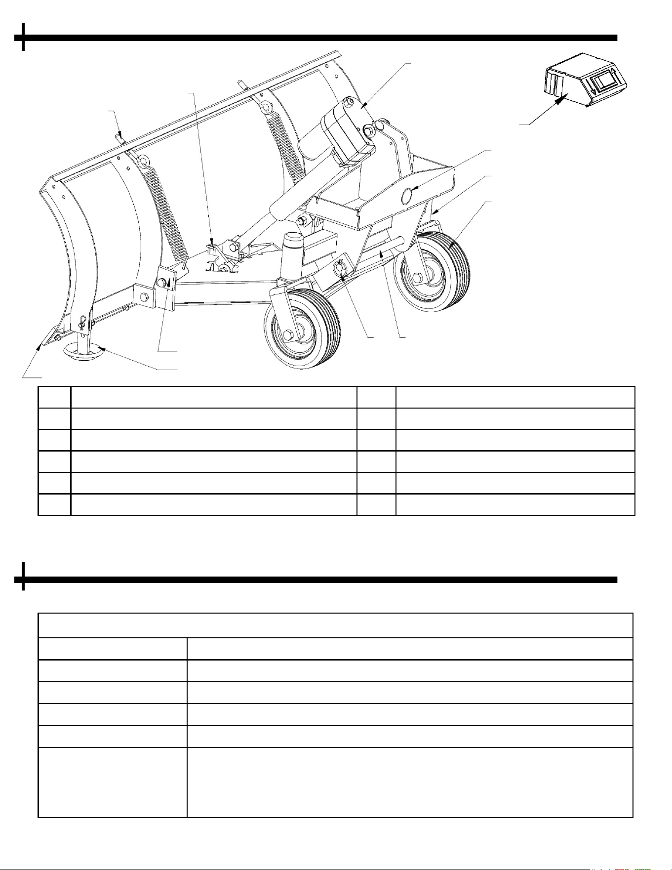
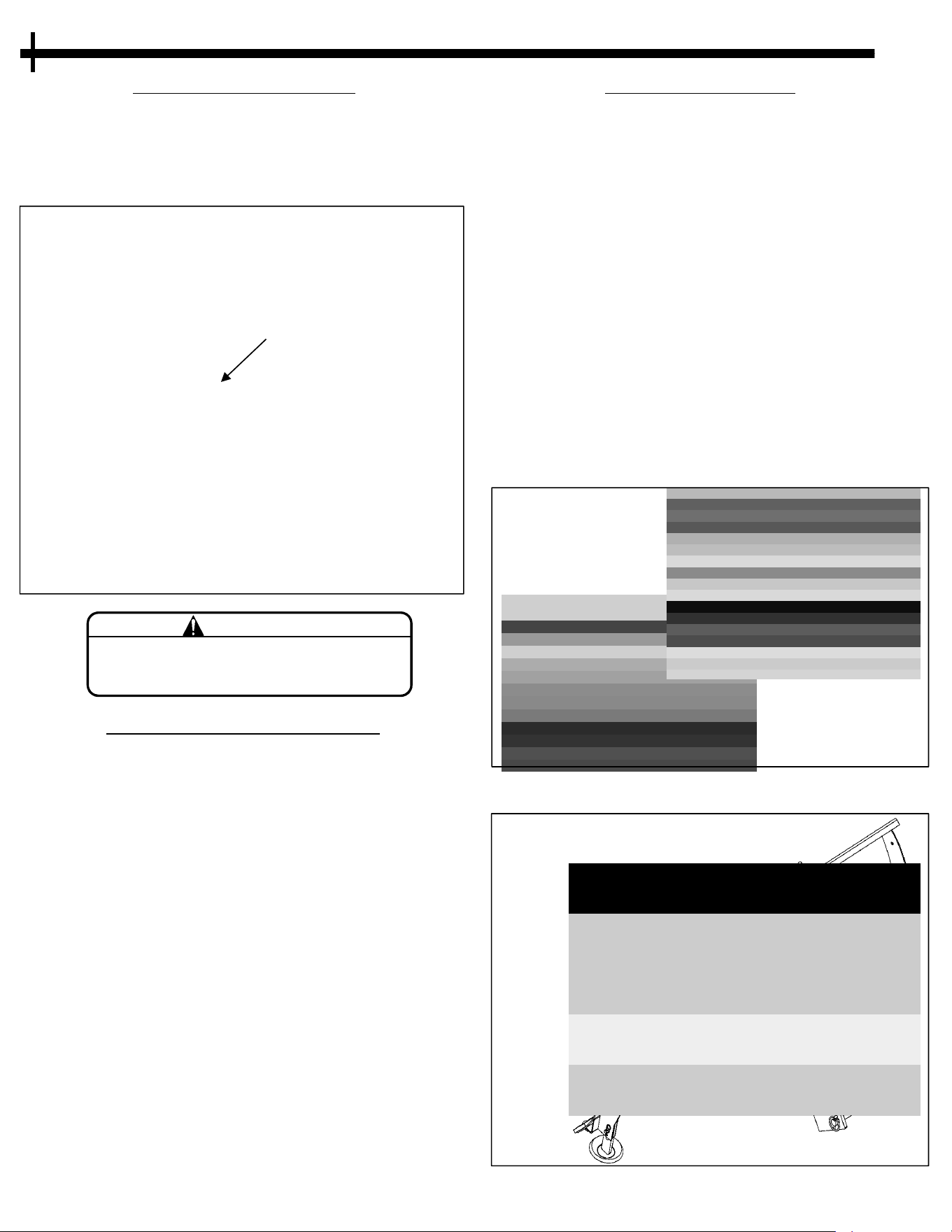
1 Adjustable Spring Tension 7
Pin Lock
2 Plow Side-Angle Locking Lever 8 Quick Attach Pin
3 Heavy Duty Lift Actuator 9 Premium Flat Free Tires
4 Replaceable Plow Edge 10 Sealed Ball Bearing Caster
5 Adjustable Height Skid Shoes 11 Quick Mount Receiver
6 Tilt Block (Plow tilt angle adjustment) 12 Plow Height Control Switch
FEATURES L
OCATION
7
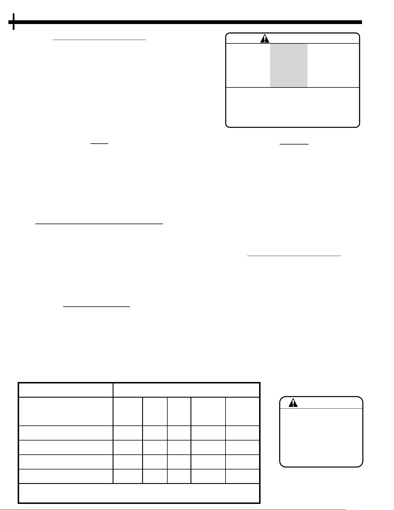
SPECIFICATIONS
P
LOW WIDTH 50 INCH
PLOW FORWARD TILT MANUAL - ADJUSTABLE
PLOW ANGLE MANUAL – ADJUSTMENT, 5 POSITION – 15° INCREMENTS
TIRE SIZE (Plow Mount) 8 X 3 SOLID, FLAT FREE RUBBER, 5/8” BEARING BORE
PLOW HEIGHT ADJUSTABLE - ELECTRIC ACTUATOR, 6” STROKE
UNIT MEASUREMENTS LENGTH: 29”
WIDTH: 50”
HEIGHT: 20”
WEIGHT: 159 lbs.
Fig. 7.1
SPECIFICATIONS
UNCRATING AND ASSEMBLY
8
Qty. Size
(2) 9/16”
(
2) 3/4”
Pry Bar
S
afety
Glasses
Gloves
Use care
w
hen
uncrating.
Claw
H
ammer
GENERAL RECOMMENDATIONS
• Use at least two people to uncrate & assemble the unit. Some components are heavy.
•
Refer to page 18 for recommended hardware torque values.
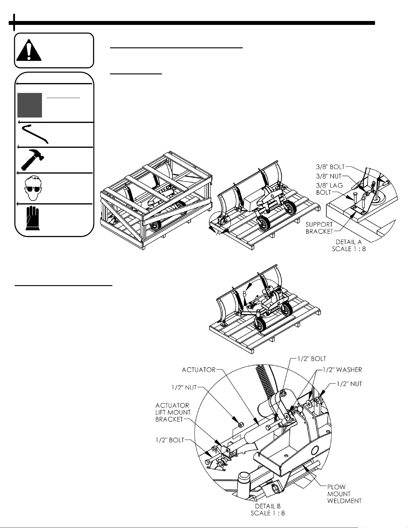
UNCRATING
• Always wear gloves and safety glasses when disassembling the crate.
•
Using a hammer and pry bar, separate the crate top, sides and ends. Use caution to
not damage the equipment inside the crate.
• Staples are used to fasten the crate together and are sharp. Use Caution!
• Remove all zip ties holding the unit to the crate base.
• Using 9/16” wrenches, remove the 3/8” Nut and Bolt and 3/8” Lag Bolts that fasten
the Support Brackets on each side of the Plow as shown in Fig. 8.1.
ASSEMBLY DIRECTIONS
1. Using 3/4” wrenches, remove the 1/2”
N
ut and Bolt from the Actuator Lift
Mount Bracket and set aside.
2. Using 3/4” wrenches, remove the 1/2”
Nut, Bolt and Washers from the Plow
Mount Weldment and set aside.
3. Remove the Actuator from the box and
assemble it using the hardware from the
previous two steps as shown in Fig. 8.2.
4. Use at least two people to carefully roll
the assembled unit off of the crate base.
Fig. 8.1
Fig. 8.2
Locking Collar
&
Pin
Pivot Shaft
Connecting and Disconnecting I
mplements
A
lways make sure that the tractor and attachment are both
on flat ground before attempting to connect or disconnect
the units.
Always check that there are no children around that can be
harmed when connecting or disconnecting units.
Always check that there are no other persons around the
immediate area that could potentially activate the tractor.
Connecting
1. Align and insert the PIVOT SHAFT of the tractor in to the
R
ECEIVER TUBE of the attachment. The tractor can be
driven to maneuver it into position or it may be necessary
to assist the connection by applying the brake to the
tractor and sliding the attachment onto the shaft.
2. Once the pivot shaft and receiver tube are fully engaged,
secure the attachment by installing the locking collar and
pin onto the pivot shaft. (See FIG. 9.1)
3. Slide the CONTROL SWITCH over the edge of the tractor
console and route the Battery wire harness lead with the
2–Pin molded connector thru the access hole in the
console base located just above the engine choke control
knob. (See FIG. 9.2)
4. To reduce the risk of short circuiting the battery for the
next step, remove the battery cover and disconnect the
BLACK
–
(negative) ground cable and wires from the
battery first and keep all cables/wires together.
5. Connect the short battery wire harness with the 2-Pin
molded connector and ring terminals to the battery.
Connect the RED +(Positive) lead first. The ring terminal on
the RED wire should connect to the battery
+
(P
ositive)
post.
6. The ring terminal on the BLACK wire should connect to
the battery
-
(Negative) post along with the main ground
cable and black wires that were disconnected in step
4
.
7. Replace the battery cover and connect the molded
connectors from the short battery wire harness to the
molded connector from the plow control switch.
8. To connect the Electric Actuator on the plow to the
Control Switch first route the remaining lead from the
control switch with the plastic connector over the console
and along the right hand side of the engine OPPOSITE OF
THE EXHAUST. Connect the plastic connector to the
mating connector of Electric Actuator. (See FIG. 9.2 & 9.3)
Disconnecting
1. On level ground, adjust the height of the plow blade so it
i
s resting on the ground and the tractor is level.
2. Unplug the control switch from the molded connector
harness for the 12V battery. Remove the switch from the
tractors console. The switch can remain connected to the
electric actuator on the plow.
3. Fold the kickstand of the tractor to the down position if
desired or if not immediately reconnecting the tractor to
another attachment.
4. Unpin the locking collar and remove it from the pivot shaft.
5. Carefully slide the tractor and attachment apart. The
tractor can be running and driven away from the
attachment if necessary.
Receiver Tube
UNCRATING AND ASSEMBLY
9
C
ontrol Switch
Control Switch
Harness lead from switch to
Ele
ctric Actuator.
Harness lead from switch
t
o Battery
Fig. 9.1
F
ig. 9.2
Harness lead from
switch to Electric
Actuator
Fig. 9.3
Operator Presence System:
R
efer to you owner’s manual for the VT389H tractor and
be sure to check that the operator presence and interlock
systems are working properly before every use. If your
Tractor does not function as described, repair the
problem immediately.
The Control Levers must be in the neutral position in
order for the machine to start. If the controls are not
exactly at neutral the unit will not start.
The snow plow does not require a PTO shaft, activating
the PTO control switch with the plow attached should
have no effects and the PTO clutch should not activate.
Tires:
M
aintain proper air pressure in all tires (SEE VT389H
operators manual SPECIFICATIONS section).
Keep tires free of gasoline, oil or insect control chemicals
which can harm rubber.
Avoid stumps, stones, deep ruts, sharp objects and other
hazards that may cause tire damage.
If operating in an area with thorns, it is recommended to
fill the tires with sealant.
Driving & Transport on Public Roads:
C
heck applicable road traffic regulations before driving
and transporting on public roads.
If the machine is transported, you should always use
adequate fastening equipment such as chains and or
nylon ratchet straps and ensure that the machine is well
anchored to the towing vehicle or trailer.
The plow attachment should also be lowered to the
lowest position and the parking brake engaged during
transport.
Plow M
aintenance:
K
eep all hardware tightened securely.
Thoroughly clean the plow attachment to remove
debris build up, especially if used in an area where ice-
melt salts have been used to prevent corrosion and
rust.
Grease the Pivot Tube using a good quality trailer
bearing grease to prevent corrosion and reduce wear.
Rotate or replace the plow edge as needed to prevent
damage to the plow frame.
WARNING
STOP THE ENGINE
AND DISCONNECT
THE SPARK PLUGS
BEFORE MAKING ANY
ADJUSTMENTS TO
THE MACHINE!
CUSTOMER RESPONSIBILITIES O
PERATION
10
VSP50
H
ours
Maintenance Schedule
Before
Each
Use
25 100
Season
Before
Storage
Check for Loose Fasteners
X X X
Grease Pivot Tube
X
1
X
Cle
an off Any Dirt or Debris
X
2
X X
Check Plow Edge for Wear
X
1 – Service more often when operating in wet, dirty or dusty conditions.
2 – Clean off more frequent when operating in corrosive conditions.
Starting:
R
efer to the VT389H owner’s manual for complete
instructions.
Before starting the tractor, be sure the area is clear of any
people or animals.
Control handles must be in the neutral lockout position.
PTO switch must be in the disengaged position
(pushed down).
Turn ignition key until engine starts. If the engine
struggles to start, engage the choke until the engine
fires, then disengage the choke when the engine
warms up.
Once started, increase the engine RPM to desired speed.
Before Operating the Plow
B
efore operating this plow attachment make sure you are
familiar and comfortable with the tractor controls and
operation and have read the tractor owner’s manual.
Make sure there are no bystanders in the area.
It is recommended to first drive around in a clear level
area to become familiar with the operation and feel of the
machine. This machine is heavy and will effect
maneuvering at different speeds.
The correct ground speed for plowing depends on the
terrain conditions and material density. Traveling too fast
can cause a loss of control and traction.
Always be aware of your surroundings while operating
the plow.
Inspect the work area before operating to make sure
there are no hidden obstacles.
A running engine gives off carbon
mo
noxide, a poisonous gas that can
kill you. Do not operate the engine in
an enclosed area. Only operate in a
well ventilated area.
DANGER
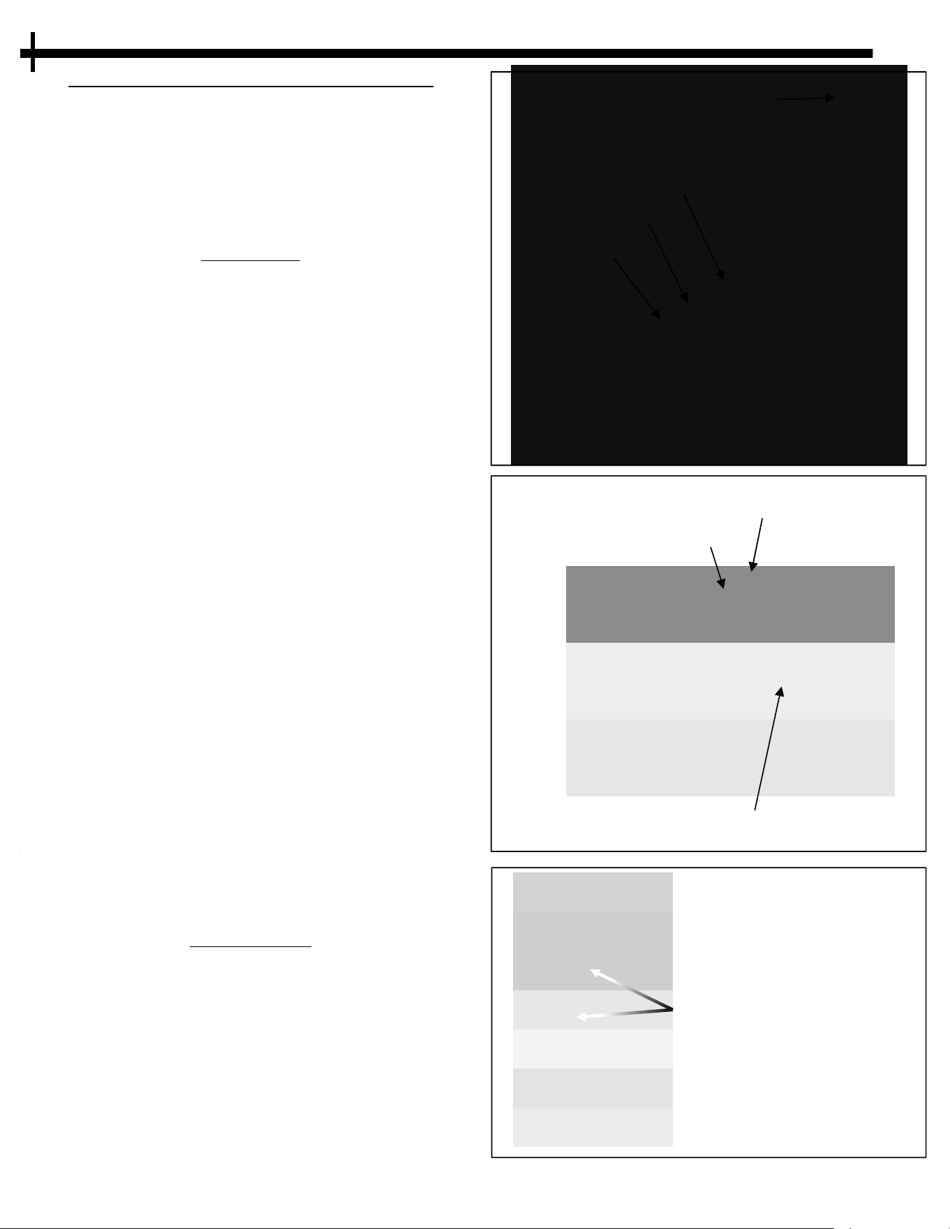
Adjusting t
he Plow Height
T
he control switch for the electric actuator should be
placed on the front hand guard (console) of the tractor
steering controls. (Fig. 11.1)
To raise and lower the plow depress the rocker switch in
the direction indicated next to the switch.
Electric actuator control
s
witch location
OPERATION
1
1
Down
Lowers Plow
Up
Raises Plow
Adjusting the Plow Tilt
T
he forward tilt angle of the plow can be set to 4
different angles. There is a Tilt Block located on both
sides of the plow. (See features on page 7, Item
number 6 & Fig 11.2).
Changing the angle will effect how the material rolls
off of the plow blade and also how aggressively the
plow “digs” under the snow. Change the angle to
suit the conditions and your preference.
1. Loosen the retaining bolt and nut enough to allow
the Tilt Blocks to rotate.
2. Once the bolt has been loosened the plow blade
can be pulled forward from the top of the plow to
extend the springs.
3. Rotate the block to set the desired tilt angle. The
hole in the block is offset in two directions allowing
a different angle according to which side of the
block is used to stop the plow blade rotation toward
the springs.
4. Retighten the retaining bolt.
Plow Springs are under tension.
Use extreme caution when working
near or on the Plow Springs!
CAUTION
Fig. 11.1
F
ig. 11.2
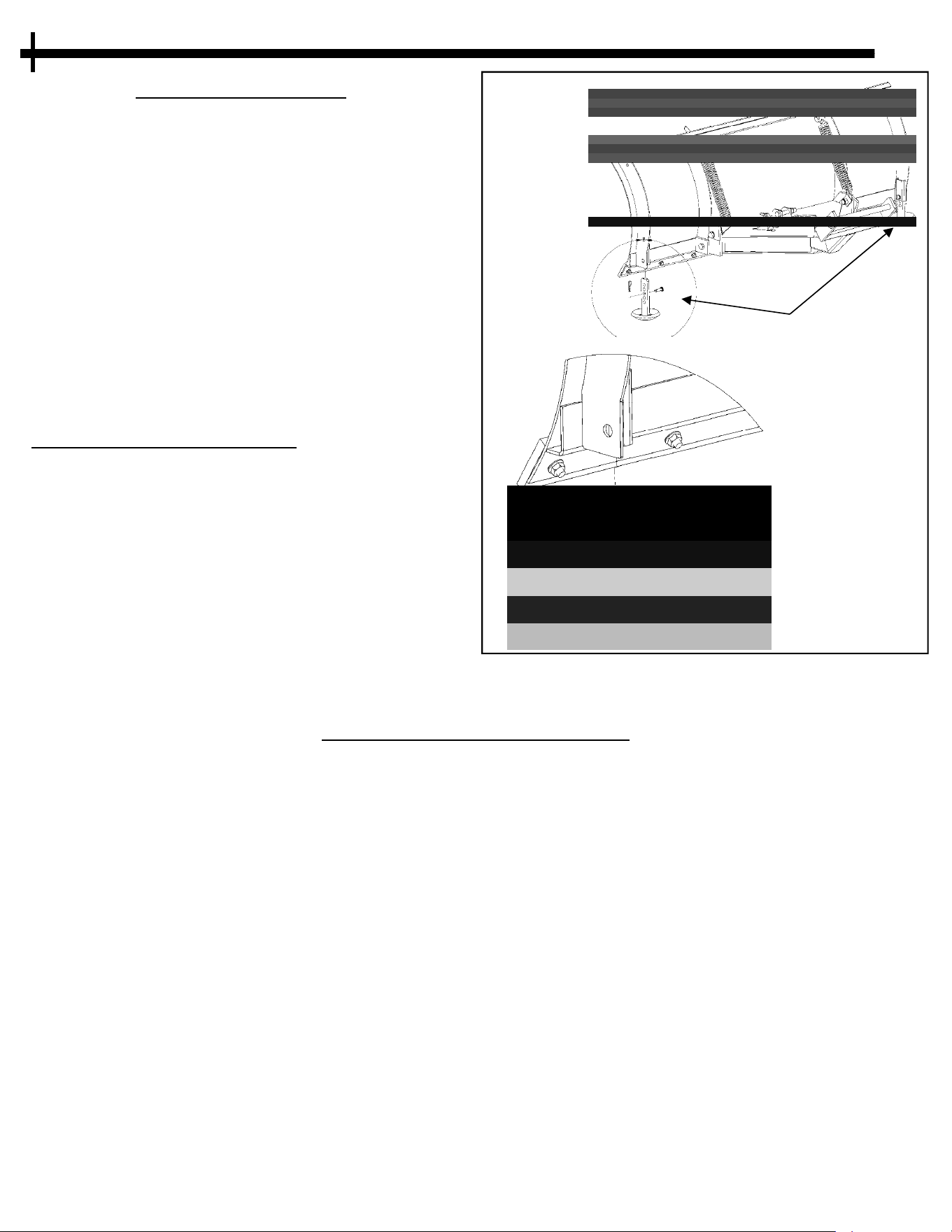
Adjusting the Tilt Spring Tension
T
he Tilt Springs allow the blade to “Trip” or “break over”
forward in the event that the plow strikes and unseen
crack, curb, or other unseen obstacle. This helps prevent
damage and causing the operator to come to an
unexpected stop. If “tripped”, back up slightly and the
plow will return when the pressure is released.
Loosening or tightening the tension on the springs will
change how much force it takes to “trip’ the plow blade.
(Refer to FIG. 11.3)
1. Remove the Thread Cap.
2. Loosen the Top Lock Nut and the Bottom Nut.
3. To INCREASE the tension and increase the force needed
to trip the plow blade, run both nuts down the eyebolt
towards the spring. To DECREASE the tension, run both
nuts up the eyebolt away from the spring.
4. Adjust both springs the same amount. You can measure
the length of the threaded eyebolt above the top lock
nut as a reference.
5. Securely tighten the nuts and replace the thread cap
Thread Cap
T
op Lock Nut
Washer
Bottom Nut
Eyebolt
Tilt Spring
Fig. 11.3
OPERATION
1
2
Locking Lever
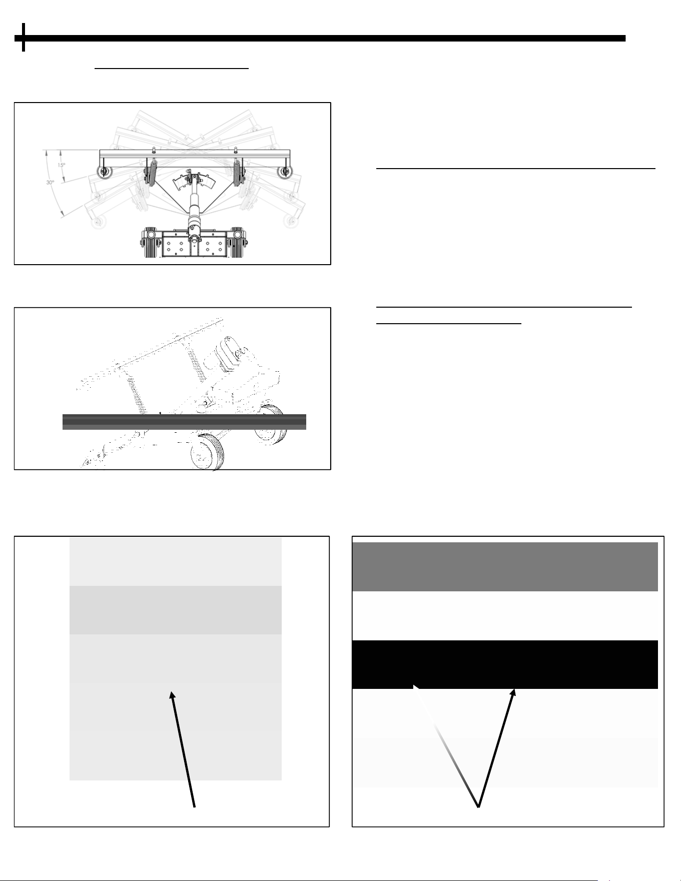
Adjusting the Plow Angle
T
he angel of the plow can be adjusted straight ahead or
in 15° degree increments to the left or to the right.
Fig. 12.2
Optional Tether
I
f using the option Tether, it should be tied to the steel
loop provided on the Locking lever. The Tether should
then be routed along the Right-Hand side of the tractor
(opposite of the engine exhaust and can be tied to the
lower handle of the console. (See FIG. 12.3 & 12.4).
To Change the Plow Angle without the tether:
1. Raise the plow above the ground so it will pivot freely.
2
. Set the Parking Brake.
3. Use one hand to pull back the Locking Lever and use
your other hand to pivot the plow blade to the desired
position.
4. Release the Locking Lever and make sure it engages
the associated slot to lock the plow in place.
5. Release the Parking Brake.
To Change the Plow Angle from operators
position with the t
ether:
1. Lower the plow so it is touching the ground.
2
. Pull the tether to release the Locking Lever and place
you hands on the tractor controls (still holding tension
on the tether). Steer the Tractor left or right. Release
the tether at the desired angle and the locking lever
will latch back in to the desired angled slot.
The angle of the plow is locked in place by a spring
loaded Locking Lever. (See FIG. 12.2)
An optional tether is supplied with the plow to allow the
operator to release the locking lever from the operator’s
position if desired. (FIG. 12.3)
Optional Tether
Fig. 12.4
Fig. 12.1
Fig. 12.3
OPERATION
1
3
Adjusting The Skid Shoes
S
kid shoes located on both ends of the plow are
adjustable and are designed to limit how close the plow
edge is to the surface you are plowing.
Skid shoes may be removed to plow smooth surfaces
with out large cracks or gravel but it is recommended
they are used to reduce wearing the plow edge and also
to prevent the plow edge from damaging the surface or
catching on cracks or embedded rocks which could
cause the plow to trip forward. Catching a large crack in
concrete or asphalt surfaces may also cause the plow to
damage the edge of the concrete/asphalt causing the
crack to become larger. Caution should be used to
prevent damaging the surface you are plowing.
Using the skid shoes to plow gravel surfaces such as
driveways can help keep the gravel in the driveway and
not become pushed off in to the grass or ditches.
To Adjust the Skid Shoe Height:
1. Refer to FIG. 7.1 item number 5 & FIG. 12.2 for skid
s
hoe location.
2. Raise the plow high enough to allow the skid shoes to
be lowered to the desired position.
3. Remove the pins from the skid shoe that hold them in
place.
4. Raise or lower the skid shoe to the desired position.
5. Replace the pins.
6. Repeat the steps for the skid shoe on the opposite end
of the plow.
Fig. 12.2
S
kid Shoe Locations
T
his plow is intended to move fresh fallen snow.
Plow after every 3” of heavy snowfall. Snow may
accumulate rapidly and make it more difficult to plow if
you wait until the snow has stopped.
Avoid ramming the plow into piles of snow.
When plowing large areas, angle the plow to one side
and create a single path in the center. Push the snow to
the outer edges in successive passes.
In deep or heavier “wet” snow, use only ½ to ¾ of the
plow bade length and overlap each pass to help keep
traction as well as to keep snow from falling outside of
the plow edge.
When done with a plowing pass, back up slightly from
the snow pile before raising the plow blade.
The plow cannot break through ice.
Use the “Straight Position” to plow straight paths and
leave the pile of snow at the end of each row.
Be aware of immovable objects that could be hidden
from view.
Plowing Instructions and Guidelines:
1. B
egin plowing by adjusting the plow to the best angle
so the snow rolls off the plow to the side in the desired
direction.
2. Lower the plow so it contacts the surface and will follow
the ground contour, the front caster wheels may raise
up off of the ground giving the plow extra down
pressure.
3. Clear the area by pushing the snow to the ends of drives
or around perimeters.
4. Treat the surface after plowing with snow and ice melt
materials as needed.
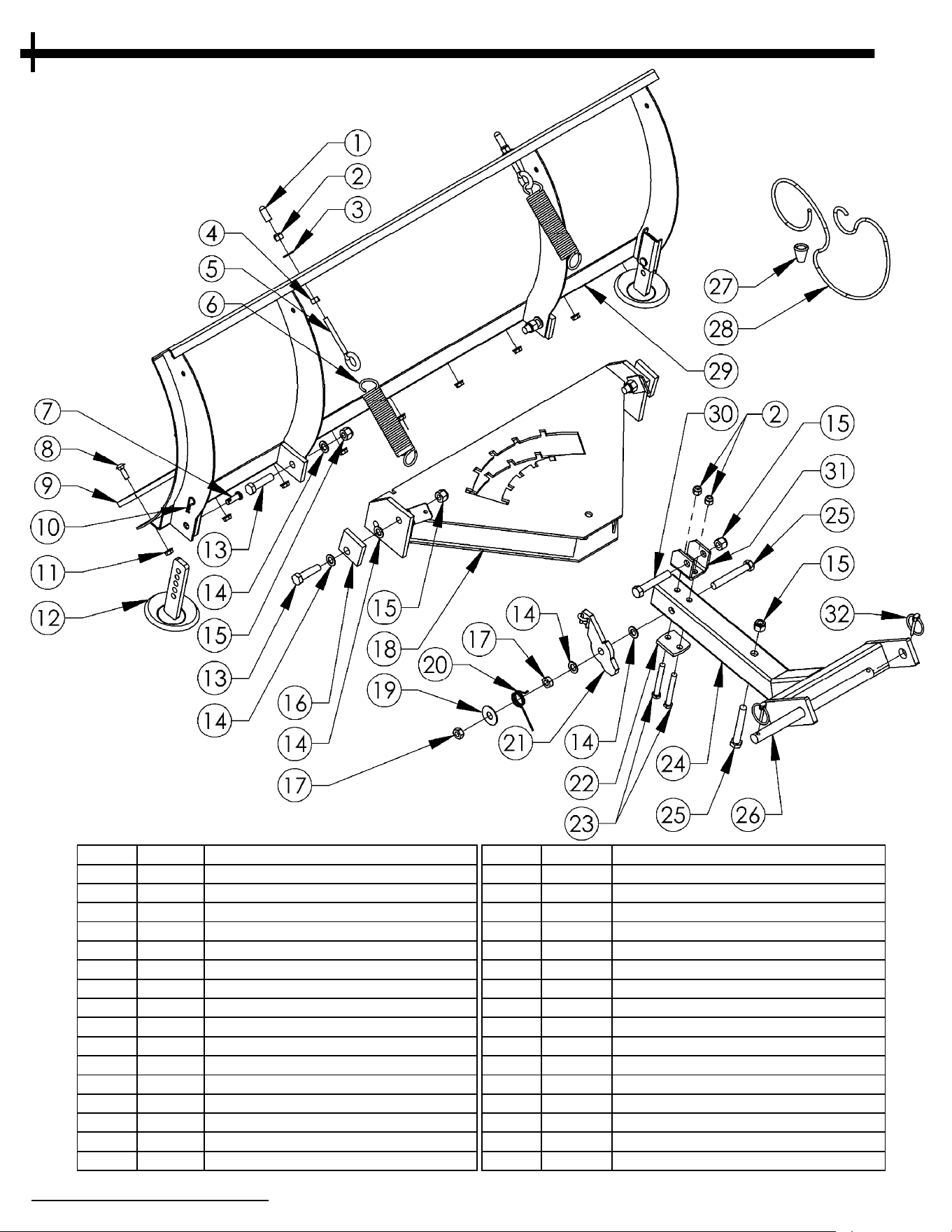
PARTS IDENTIFICATION
1
4
Item # Part # Description Item # Part # Description
1 AS125 Cap - Round Vinyl, Black 17 NB121 Nut - Jam Lock, 1/2-13 2-Way
2 NB182 Nut - Nyloc 3/8-16 18 2323* Pivot - Weldment
3 NB272 Washer - SAE Flat 3/8 19 TR150W Washer - .531 X 1 1/2 X .062
4 NB212 Nut - HNC, 3/8-16 20 2336 Spring - Pivot
5 NB635 Eyebolt - Turned 3/8-16 X 3 21 2319* Latch - Lever Assembly
6 2335 Spring - Tilt 22 2310* Bracket - Support; Plow
7 NB300 Pin - Clevis, 3/8 X 1 1/8 23 NB150 Bolt - 3/8-16 X 3 HCC
8 10197 Bolt - Carriage 5/16-18 X 1 24 2588* Mount - Plow Weldment
9 20084* Edge - Cut, Reversable .375 X 2.5 X 50 25 NB577 Bolt - 1/2-13 X 3 1/2
10 NB127 Pin - Hair, #39 26 2642* Pin - Plow Mount, 3/4 X 12
11 NB170 Nut - Serrated Flange 5/16-18 27 H7K Knob - Rope
12 10068* Skid - Weldment 28 H9B Rope - Red
13 NB509 Bolt - 1/2-13 X 2 HCC 29 2150* Blade - Rolled Weldment, 50
14 NB177 Washer - Mach 1/2 30 NB131 Bolt - 1/2-13 X 3 HCC
15 NB281 Nut - Nyloc 1/2-13 31 22131* Bracket - Actuator Lift Mount
16 2331* Block - Tilt 32 NB506 Pin - Lynch, 3/16
When ordering replacement parts
*USE PAINT CODE: GT=GREY TK=BLACK
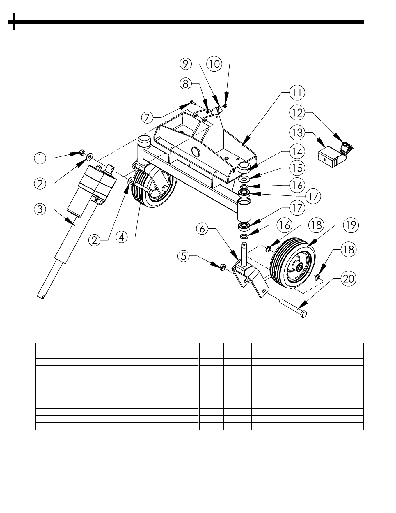
PARTS IDENTIFICATION
1
5
When ordering replacement parts
*USE PAINT CODE: GT=GREY TK=BLACK
ITEM
NO.
PART # DESCRIPTION
ITEM
NO.
PART # DESCRIPTION
1 NB281 Nut - Nyloc 1/2-13 11 22052* Plow Mount Weldment
2 NB555 Washer - USS Flat, 1/2 ZY 12 19978 Switch - DPDT, 30A, On-Off-On MOM
3 22130 Actuator-12VDC,20:1, 6",1000#,17.7x23.7 13 22062* Switch Box
4 NB131 Bolt - 1/2-13 X 3 HCC 14 094618 Bearing Cap
5 NB595 Nut - Lock Jam, 5/8-11 2 Way Grade A 15 17X195 Washer - .768 X 1.814 X .060
6 22060* Caster Weldment 16 NB195 Washer - 13/16 X 1 1/4 X 1/8 ZY
7 NB690 Bolt - Serr Flange, 1/4-20 X 3/4 GR5 ZY 17 B98 Bearing, 6204-2RS, 20mm Bore
8 15355 Fitting - Grease Zerk 18 NB149 Washer - 5/8 ID X 1 OD 14 GA ZY
9 14316 Wire Clamp, 3/8" x 1/4" Hole 19 21284 Tire/Wheel With Bearing - 8 X 3, Solid
10 NB524 Nut - Serr Flange, 1/4-20 Grade 5 ZY 20 19642 Bolt - 5/8-11 X 5 GR5 ZY

Attachment I
dentification
Each attachment has its own model number
and serial number. The number for the
attachment can be found on the side of the
upper mounting plate for the electric actuator
(refer to Symbols & Decal section for reference).
All parts listed herein may be ordered directly
from Swisher or your nearest Swisher dealer.
WHEN ORDERING PARTS, PLEASE HAVE THE FOLLOWING INFORMATION AVAILABLE:
•M
ODEL NUMBER - __________________________________________________________
•SERIAL NUMBER - __________________________________________________________
•DATE PURCHASED - ________________________________________________________
•PURCHASE FROM - _________________________________________________________
•PART NUMBER (W/ PAINT CODE) - ____________________________________________
•PART DESCRIPTION - _______________________________________________________
www.swisherinc.com
TE
LEPHONE - 1-800-222-8183
FAX - 1-660-747-8650
S.A.I.
1602 CORPORATE DRIVE
WARRENSBURG, MO 64093
Unauthorized Replacement Parts
Use only Swisher replacement parts. The
re
placement of any part on this unit with
anything other than a Swisher authorized
replacement part may adversely affect the
performance, durability and safety of this unit
and may void the warranty. Swisher disclaims
liability for any claims or damages, whether
warranty, property damage, personal injury or
death arising out of the use of unauthorized
replacement parts.
cust.[email protected]
PRODUCT IDENTIFICATION
1
6

Ҧ
NOTES
17

TORQUE REFERENCE GUIDE
1
8

The manufacturer’s warranty to the original consumer purchaser is:
T
his product is free from defects in materials and workmanship for a period of three (3) years for
residential use and one (1) year for commercial use from the date of purchase by the original
consumer purchaser.
We will repair or replace, at our discretion, parts found to be defective due to materials or
workmanship. This warranty is subject to the following limitations and exclusions:
1) Limitations
This warranty applies only to products which have been properly assembled, adjusted, and
operated in accordance with the instructions contained within this manual. This warranty
does not apply to any product of Swisher that has been subject to alteration, misuse, abuse,
improper assembly or installation, shipping damage, or to normal wear of the product.
2) Exclusions
Excluded from this warranty are normal wear, normal adjustments, normal maintenance,
In the event you have a claim under this warranty, you must deliver the product to an authorized
service dealer. All transportation charges, damage or loss incurred during transportation of parts
submitted for replacement or repair under this warranty shall be borne by the purchaser. Should
you have any questions concerning this warranty, please contact us toll-free at 1-800-222-8183.
The model number, serial number, date of purchase and the name of the authorized Swisher
dealer from whom you purchased the mower will be needed before any warranty claim can be
processed.
THIS WARRANTY DOES NOT APPLY TO ANY INCIDENTAL OR CONSEQUENTIAL DAMAGES AND
ANY IMPLIED WARRANTIES ARE LIMITED TO THE SAME TIME PERIODS STATED HEREIN FOR
ALL EXPRESSED WARRANTIES. Some states do not allow the limitation of consequential damages
or limitations on how long an implied warranty may last, so the above limitations or exclusions
may not apply to you. This warranty gives you specific legal rights and you may have other rights,
which vary from state-to-state. This is a limited warranty as defined by the Magnuson-Moss Act of
1975.
LIMITED WARRANTY
1
9
Ҧ
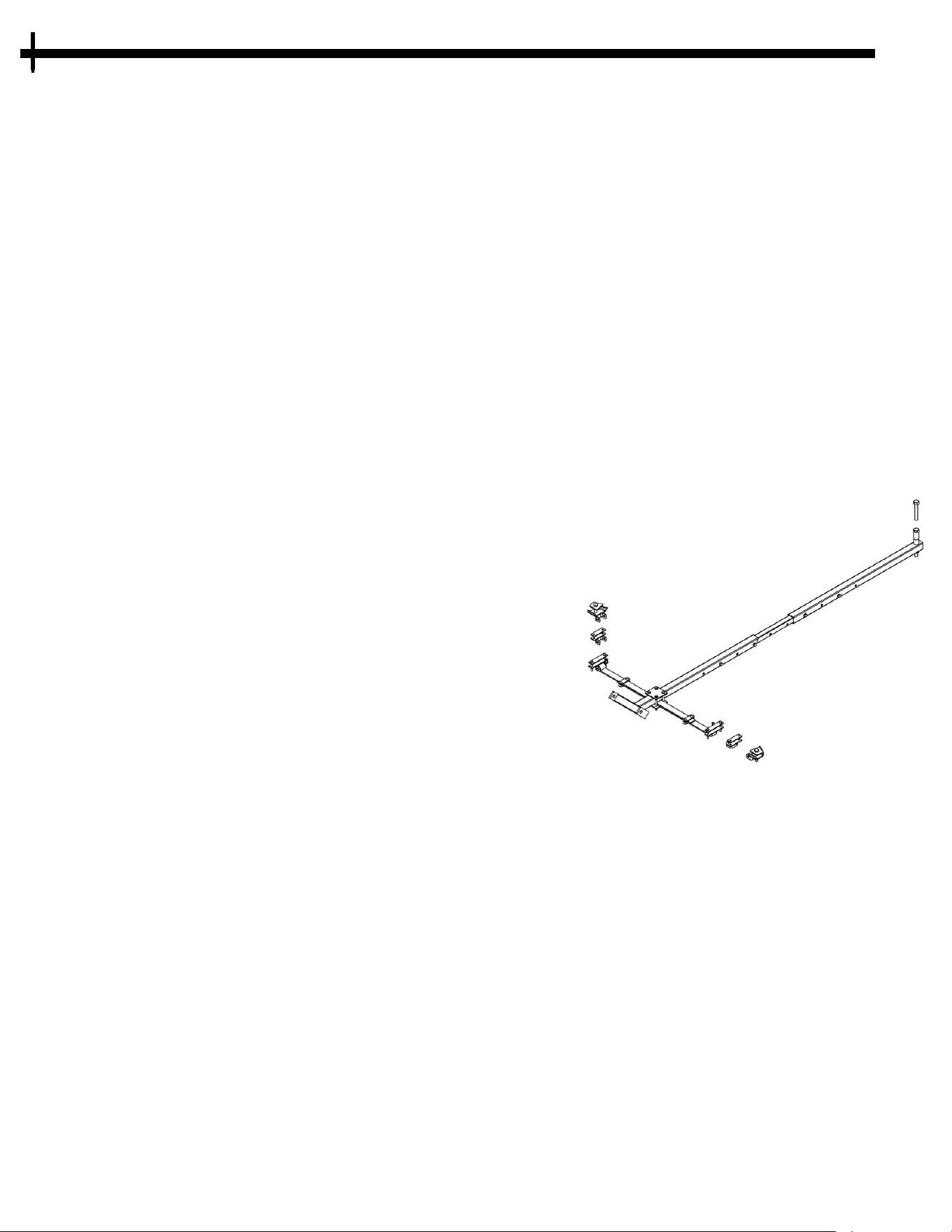
20
Accessories
U
niversal Mounting Kit 2646
Fits most ATV's
Leaf spring frame
Attaches to rear hitch and front A-arms
Frame is super-duty steel square tubing
No ground clearance issues
Durable powder coat finish
Used in conjunction with Swisher Plow Blades
or Swisher Dump Bucket .
The plow of the VERSA VSP50 may be disconnected form the mount by removing the Quick
Attach Pin And the bottom actuator bolt to be used on these other quality mounting system for
your ATV or UTV.
Universal Mount Kit, UTV Comm. Pro - 2
0096
Fits most UTV's
Leaf spring frame
Attaches to rear hitch and front A-arms
Frame is super-duty steel square tubing
No ground clearance issues
Durable powder coat finish
Used in conjunction with Swisher Plow Blades or Swisher Dump Bucket.
UTV Universal Mounting Kit 10260
A
ttaches to atv or UTV front 2"x2" receiver hitch
Heavy duty steel tubing
Tough powder coat finish
One pin attachment to interchange accessories

Back before electricity came to rural Missouri Max Swisher was producing lawn
m
owers from his mother’s chicken house. Max never liked to mow grass. He
installed a gearbox on his family’s lawn mower creating a self-propelled unit. By tying
one end of a rope to the mower and the other end to a tree in the center of the yard
the mower circled the tree, shortening the rope and guiding the mower in concentric
circles. Max enjoyed relaxing under a shade tree while his invention did all the work.
Max had designed his first self-propelled rotary lawn mower to do his dirty work for
him. Neighbors noticed his new invention and began asking him to make more.
Today, over 70 years later, Swisher is still producing innovative lawn and garden and
ATV/UTV equipment designed to give us all more “relaxing in the shade” time.
Swisher products have been featured nationally on television programs such as Regis
and Kathie Lee and seen in publications like ATV Magazine, Country Journal, Popular
Mechanics Magazine and others. In January 2000 Popular Mechanics Magazine
named Max’s zero turning radius riding mower one of the 20
t
h
century’s top
household inventions.
Swisher offers value and function in its products to meet your grounds maintenance
needs.
CELEBRATING 75 YEARS OF INNOVATION
SINCE 1945
SWISHER HISTORY
21

Each attachment has its own model number. The model
n
umber for the VSP50 Plow System can be found on the
side of the upper mounting plate for the electric
actuator . All attachments parts listed herein may be
ordered directly from Swisher or your nearest Swisher
dealer.
WHEN ORDERING PARTS, PLEASE HAVE THE
FOLLOWING INFORMATION AVAILABLE:
PRODUCT – VSP50 Plow Attachment
SERIAL NUMBER -
MODEL NUMBER -
PART NUMBER -
PART DESCRIPTION -
TELEPHONE - 1-800-222-8183
FAX - 1-660-747-8650
SWISHER ACQUISITION INC.
1602 CORPORATE DRIVE
WARRENSBURG, MO 64093
www.swisherinc.com
OWNER’S
MA
NUAL
www.swisherinc.com
CHANGING YOUR LANDSCAPE SINCE 1945
IMPORTANT
R
ead and follow all
Safety Precautions
and Instructions
before operating this
equipment.
MODEL NO.
VSP50
Commercial Pro Land
Ma
nagement System
50” Snow Plow Attachment
