Caution:
Read and fol low
all Safety Rules
and In struc tions
Be fore Op er at ing
This Equip ment
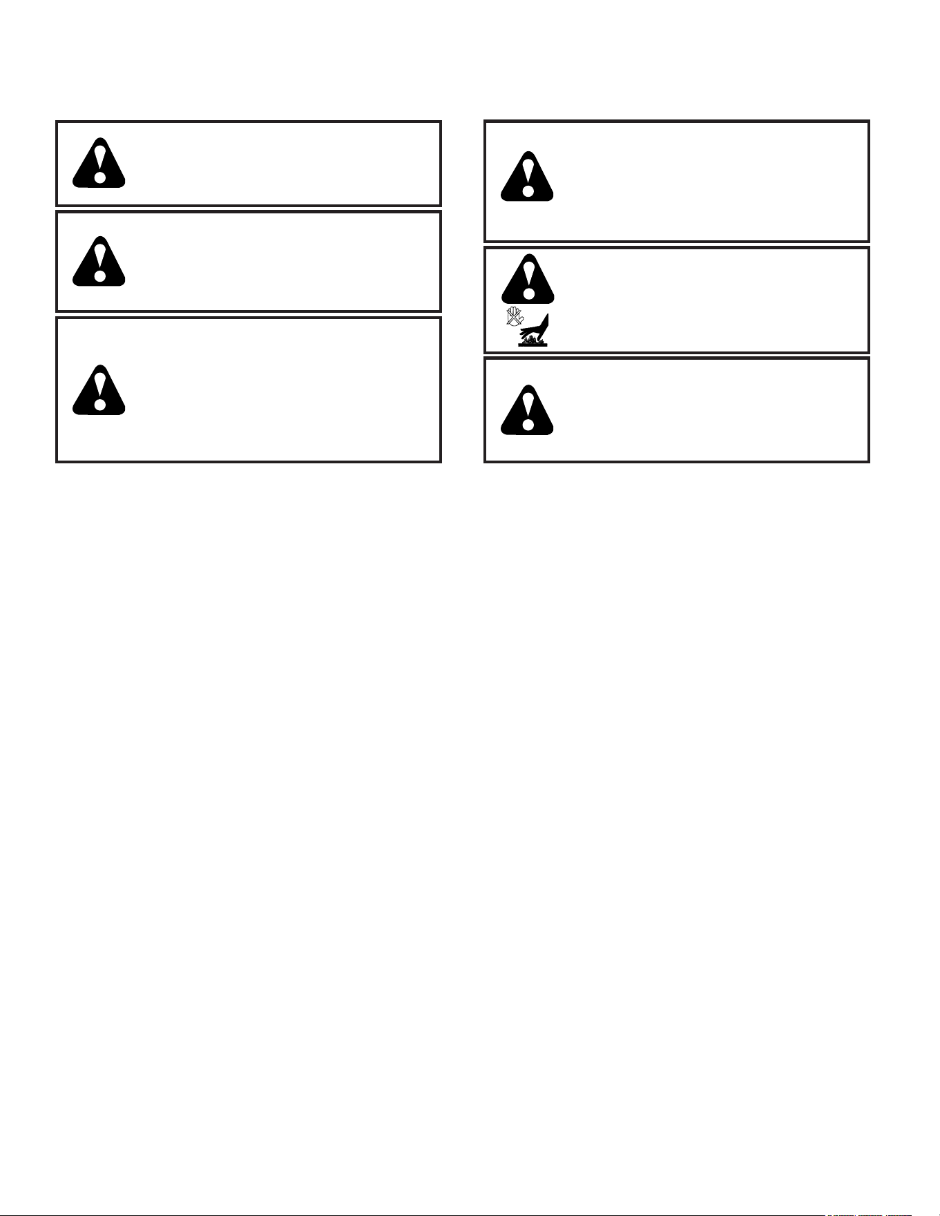
MODEL NO.
944.103251
OWNER’S
MANUAL
• Assembly
• Operation
• Maintenance
• Service and Adjustments
• Repair Parts
1150 SERIES B&S ENGINE
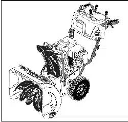
27" TWO-STAGE
POWER-PROPELLED
SNOW THROWER
Sears Canada, Inc., Toronto, Ontario M5B 2B8
589430501
Gasoline containing up to 10% ethanol (E10) is acceptable for use in this machine.
The use of any gasoline exceeding 10% ethanol (E10) will void the product warranty.
2
IMPORTANT
Safe Operation Practices for Walk-Behind Snow Throwers
This snow thrower is capable of amputating hands and feet and throwing objects.
Failure to observe the following safety instructions could result in serious injury.
WARNING: This snow thrower is for
use on sidewalks, driveways and other
ground level surfaces. Caution should
be exercised while using on sloping
surfaces. Do not use snow thrower on
surfaces above ground level such as
roofs of residences, garages, porch es
or other such structures or buildings.
WARNING: Snow throwers have ex-
posed rotating parts, which can cause
severe injury from contact, or from ma-
terial thrown from the discharge chute.
Keep the area of operation clear of all
persons, small children and pets at all
times including startup.
WARNING: Always disconnect spark
plug wire and place it where it can not
con tact plug in order to pre vent ac ci-
den tal start ing when setting up, trans-
port ing, ad just ing or making re pairs.
Look for this symbol to point out im-
por tant safety precautions. It means
CAUTION!!! BE COME ALERT!!! YOUR
SAFE TY IS IN VOLVED.
CAUTION: Muffler and other engine
parts become extremely hot during
operation and remain hot after engine
has stopped. To avoid severe burns on
contact, stay away from these areas.
WARNING: Engine exhaust, some of
its con stit u ents, and certain vehicle
com po nents contain or emit chem i-
cals known to the State of Cal i for nia
to cause can cer and birth defects or
oth er re pro duc tive harm.
(f) Keep the nozzle in contact with the rim of the fuel
tank or container opening at all times, until refueling
is complete. Do not use a nozzle lock-open device.
(g) Replace gasoline cap securely and wipe up spilled
fuel.
(h) If fuel is spilled on clothing, change clothing im-
mediately.
5. Use extension cords and receptacles as specified by
the manufacturer for all units with electric drive motors
or electric starting motors.
6. Adjust the collector housing height to clear gravel or
crushed rock surface.
7. Never attempt to make any adjustments while the
engine (motor) is running (except when specifically
recommended by manufacturer).
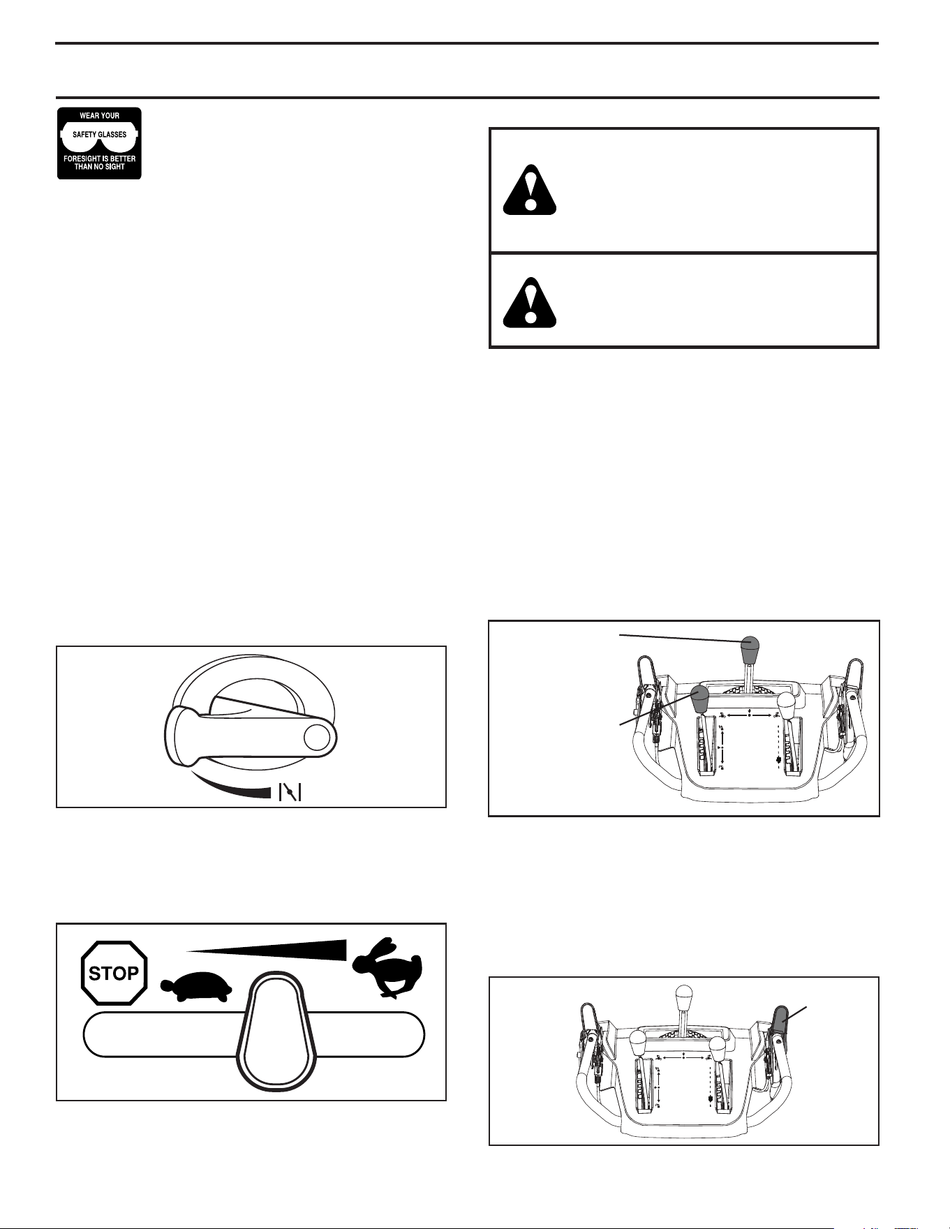
8. Always wear safety glasses or eye shields during op-
eration or while performing an adjustment or repair to
protect eyes from foreign objects that may be thrown
from the machine.
Operation
1. Do not put hands or feet near or under rotating parts.
Keep clear of the discharge opening at all times.
2. Exercise extreme caution when operating on or cross-
ing gravel drives, walks, or roads. Stay alert for hidden
hazards or traffic.
3. After striking a foreign object, stop the engine (motor),
remove the wire from the spark plug, disconnect the
cord on electric motors, thoroughly inspect the snow
thrower for any damage, and repair the damage before
restarting and operating the snow thrower.
4. If the unit should start to vibrate abnormally, stop the
engine (motor) and check immediately for the cause.
Vibration is generally a warning of trouble.
5. Stop the engine (motor) whenever you leave the oper-
ating position, before unclogging the collector/impeller
housing or discharge chute, and when making any
repairs, adjustments or inspections.
Training
1. Read, understand and follow all instructions on the
machine and in the manual(s) before operating this
unit. Be thoroughly familiar with the controls and the
proper use of the equipment. Know how to stop the
unit and disengage the controls quickly.
2. Never allow children to operate the equipment. Never
allow adults to operate the equipment without proper
instruction.
3. Keep the area of operation clear of all persons, par-
ticularly small children.
4. Exercise caution to avoid slipping or falling, especially
when operating the snow thrower in reverse.
Preparation
1. Thoroughly inspect the area where the equipment is
to be used and remove all doormats, sleds, boards,
wires, and other foreign objects.
2. Disengage all clutches and shift into neutral before
starting the engine (motor).
3. Do not operate the equipment without wearing adequate
winter garments. Avoid loose fitting clothing that can
get caught in moving parts. Wear footwear that will
improve footing on slippery surfaces.
4. Handle fuel with care; it is highly flammable
(a) Use an approved fuel container.
(b) Never add fuel to a running engine or hot engine.
(c) Fill fuel tank outdoors with extreme care. Never fill
fuel tank indoors.
(d) Never fill containers inside a vehicle or on a truck
or trailer bed with a plastic liner. Always place
containers on the ground, away from your vehicle,
before filling.
(e) When practical, remove gas-powered equipment
from the truck or trailer and refuel it on the ground.
If this is not possible, then refuel such equipment
on a trailer with a portable container, rather than
from a gasoline dispenser nozzle.

3
6. When cleaning, repairing or inspecting the snow thrower,
stop the engine and make certain the collector/impel-
ler and all moving parts have stopped. Disconnect
the spark plug wire and keep the wire away from the
plug to prevent someone from accidentally starting the
engine.
7. Do not run the engine indoors, except when starting
the engine and for transporting the snow thrower in or
out of the building. Open the outside doors; exhaust
fumes are dangerous.
8. Exercise extreme caution when operating on slopes.
9. Never operate the snow thrower without proper guards,
and other safety protective devices in place and working.
10. Never direct the discharge toward people or areas
where property damage can occur. Keep children and
others away.
11. Do not overload the machine capacity by attempting
to clear snow at too fast a rate.
12. Never operate the machine at high transport speeds
on slippery surfaces. Look behind and use care when
operating in reverse.
13. Disengage power to the collector/impeller when snow
thrower is transported or not in use.
14. Use only attachments and accessories approved by
the manufacturer of the snow thrower (such as wheel
weights, counterweights, or cabs).
15. Never operate the snow thrower without good visibility
or light. Always be sure of your footing, and keep a firm
hold on the handles. Walk; never run.
16. Never touch a hot engine or muffler.
Clearing a Clogged Discharge Chute
Hand contact with the rotating impeller inside the discharge
chute is the most common cause of injury associated with
snow throwers. Never use your hand to clean out the dis-
charge chute. To clear the chute:
1. SHUT THE ENGINE OFF!
2. Wait 10 seconds to be sure the impeller blades have
stopped rotating.
3. Always use a clean-out tool, not your hands.
Maintenance and Storage
1. Check shear bolts and other bolts at frequent intervals
for proper tightness to be sure the equipment is in safe
working condition.
2. Never store the machine with fuel in the fuel tank inside
a building where ignition sources are present such as
hot water heaters, space heaters, or clothes dryers.
Allow the engine to cool before storing in any enclosure.
3. Always refer to operator’s manual for important details
if the snow thrower is to be stored for an extended
period.
4. Maintain or replace safety and instruction labels, as
necessary.
5. Run the machine a few minutes after throwing snow
to prevent freeze-up of the collector/impeller.
MAINTENANCE ..................................................... 14-15
SERVICE AND AD JUST MENTS ........................... 16-18
STORAGE ................................................................... 19
TROU BLE SHOOT ING ................................................ 20
REPAIR PARTS ..................................................... 22-42
ENGINE BREAKDOWN ......................................... 43-47
SAFETY RULES ........................................................ 2-3
PRODUCT SPECIFICATIONS ...................................... 3
CUSTOMER RESPONSIBILITIES ................................ 3
WARRANTY .................................................................. 4
ASSEMBLY / PRE-OPERATION ............................... 5-7
OPERATION ............................................................ 8-13
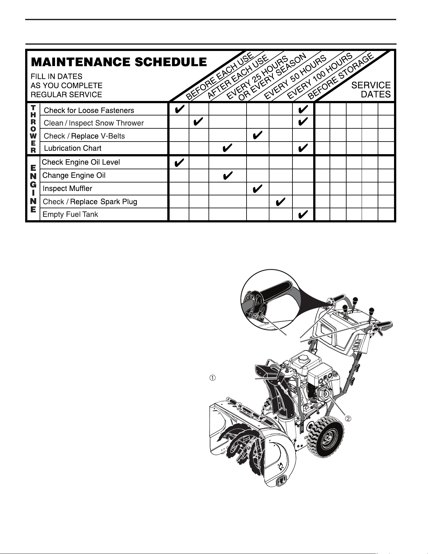
MAINTENANCE SCHEDULE ..................................... 14
TABLE OF CONTENTS
CONGRATULATIONS on your purchase of a new snow
thrower. It has been designed, engineered and man u fac-
tured to give best possible dependability and per for mance.
Should you experience any problem you cannot easily
remedy, please contact your nearest authorized service
center. We have competent, well-trained tech ni cians and
the proper tools to service or repair this unit.
Please read and retain this manual. The instructions will
enable you to assemble and maintain your snow thrower
prop er ly. Always observe the “SAFETY RULES”.
SERIAL NUMBER: ___________________________
DATE OF PURCHASE: _______________________
THE MODEL AND SERIAL NUMBERS WILL BE FOUND
ON A DECAL ATTACHED TO THE REAR OF THE SNOW
THROWER HOUSING.
YOU SHOULD RECORD BOTH SERIAL NUMBER AND
DATE OF PURCHASE AND KEEP IN A SAFE PLACE
FOR FUTURE REFERENCE.
CUSTOMER RESPONSIBILITIES
• Read and observe the safety rules.
• Follow a regular schedule in maintaining, caring for
and using your snow thrower.
• Follow the instructions under “Maintenance” and “Stor-
age” sec tions of this own er’s manual.
PRODUCT SPECIFICATIONS
Gasoline Capacity 0.8 Gallons (3,0 Liters)
and Type: Unleaded Regular only
Oil Type SAE 5W-30 or 10W-30
(API SG–SL): Synthetic SAE 5W-30
Oil Capacity: 20 Ounces (0,6 Liters)
Spark Plug: Champion QC12YC
Gap: 0.030" (0,762 mm)

4
GENERAL: Craftsman products are warranted to be free from defects in materials or workmanship for a specific time period
as set-out below (the “Warranty Period”). Warranties extend to the original purchaser of a Craftsman product only. Purchases
made through an online auction or through any website other than www.sears.ca are excluded. The relevant Warranty Period
commences on the original date of purchase. Within this period, SEARS CANADA, Inc. will, at its sole option, repair or replace
any products or components which fail in normal use. Such repairs or replacement will be made at no charge to the customer for
parts or labor, provided that the customer shall be responsible for any transportation cost.
EXCLUSIONS: This warranty does not cover failures due to normal wear, abuse, misuse, neglect (including but not limited to
the use of stale fuel, dirt, abrasives, moisture, rust, corrosion, or any adverse reaction due to improper storage or use habits),
improper maintenance or failure to follow maintenance guidelines and/or instructions, failure to operate the product in accordance
with the owner’s manual or any additional instructions or information provided at the time of purchase or in subsequent
communications with the original purchaser, accident or unauthorized alterations or repairs made or attempted by others. Also
excluded from warranty coverage - except as provided below - are the following: maintenance, adjustments, components subject
to wear including but not limited to: cosmetic components, belts, blades, blade adapters, bulbs, tires, filters, guide bars, lubricants,
seats, grips, recoil assy’s, saw chains and bars, trimmer lines and spools, spark plugs, starter ropers and tines, and discoloration
resulting from ultraviolet light. Any product missing the model and/or serial number identification label will be disqualified from
coverage under this warranty.
REPAIRS: Repairs have a 90 day warranty. If the defective product is still within the Warranty Period, then the new warranty is 90
days from the date of repair or to the end of the original Warranty Period, whichever period is longer.
DISCLAIMERS: THE WARRANTIES AND REMEDIES CONTAINED HEREIN ARE EXCLUSIVE AND IN LIEU OF ALL OTHER
WARRANTIES, WHETHER ORAL OR WRITTEN (OTHER THAN AS STATED HEREIN), AND WHETHER EXPRESS, IMPLIED
OR STATUTORY, INCLUDING BUT NOT LIMITED TO ANY. THIS WARRANTY GIVES YOU SPECIFIC LEGAL RIGHTS, WHICH
MAY VARY FROM PROVINCE TO PROVINCE.
IN NO EVENT SHALL SEARS BE LIABLE FOR ANY INCIDENTAL, SPECIAL, INDIRECT OR CONSEQUENTIAL DAMAGES,
WHETHER RESULTING FROM THE USE, MISUSE OR INABILITY TO USE THE PRODUCT OR FROM DEFECTS IN THE
PRODUCT. THE EXCLUSIONS IN THIS PARAGRAPH SHALL NOT APPLY IN JURISDICATIONS WHERE APPLICABLE LAW
DOES NOT ALLOW FOR THE EXCLUSION OF INCIDENTAL OR CONSEQUENTIAL DAMAGES. IN SUCH JURISDICTIONS,
THIS PARAGRAPH SHALL NOT APPLY, BUT THE REMAINING PROVISIONS OF THIS DOCUMENT SHALL REMAIN VALID.
SEARS retains the exclusive right to repair or replace the product or offer a full refund of the purchase price at its sole discretion.
SUCH REMEDY SHALL BE YOUR SOLE AND EXCLUSIVE REMEDY FOR ANY BREACH OF WARRANTY.
CUSTOMER RESPONSIBILITIES: In additional to complying with all suggested maintenance guidelines and instructions,
customers’ obligations shall include but shall not be limited to: operating the product in accordance with the owner’s manual or
any additional instructions or information provided at the time of purchase or in subsequent communications to the purchaser from
time to time, exhibit reasonable care in the use, operation, maintenance, general upkeep and storage of the product. Failure to
comply with these requirements will void any applicable warranty.
LIST OF APPLICABLE WARRANTY PERIODS: The following list contains the applicable Warranty Period for your Craftsman
product and is based on a combination of the type of product or component and the intended and actual use of the product or
component:
1. 90 DAYS: Craftsman products intended for use or actually used for commercial, institutional, professional or income-
producing purposes
2. 2 YEARS: Craftsman riding lawn mowers, yard and garden tractors, walk behind mowers, tillers, brush cutters,
snow blowers, handheld blowers, backpack blowers, hedge trimmers and electrical products for noncommercial,
nonprofessional, non-institutional, or non-income-producing use, except for those components which are part of engine
systems manufactured by third party engine manufacturers for which the purchase has received an separate warranty with
product information supplied at the time of purchase.
3. 1 YEAR: Craftsman power cutters, stump grinders, pole pruners, gas chain saws, electric chain saws, trimmer
attachments, baggers and pole saws for noncommercial, nonprofessional, non-institutional, or non-income-producing use.
4. 90 DAYS: All defective batteries, which will be replaced during this 90-day Warranty Period.
5. 60 DAYS: Additional Warranty Period of 60 days will apply to adjustments and worn products or components BUT DOES
NOT INCLUDE WEAR OR ADJUSTMENTS for products used for commercial, institutional, professional or income-
producing purposes. Wear items include but are not limited to: belts, blades, tires, spark plugs, air filters, chains, shear
bolts, skid plates, scraper bars, drift cutters, ropes, tines, collection bags and pulleys.
As the Warranty Period runs from the date of purchase and NOT from the date that a product is delivered, opened, assembled or
first used, please ensure during this time period that your product or component has been assembled and tested for correction
operation regardless of when you intend to actually use it. Claims made after the Warranty Period has expired will not be
honored.
PROOF OF PURCHASE/DOCUMENTATION: Warranty coverage is conditioned upon the original purchaser furnishing SEARS
CANADA or its authorized third party service provider if applicable, with the original sales receipt or other adequate written proof
of the original purchase date and identification of the product. In the event that the original purchaser is unable to provide a
company of the original sales receipt, SEARS CANADA Inc. reserves the right to determine in its sole discretion what other written
proof of the original purchase date and identification of the product is acceptable.
5
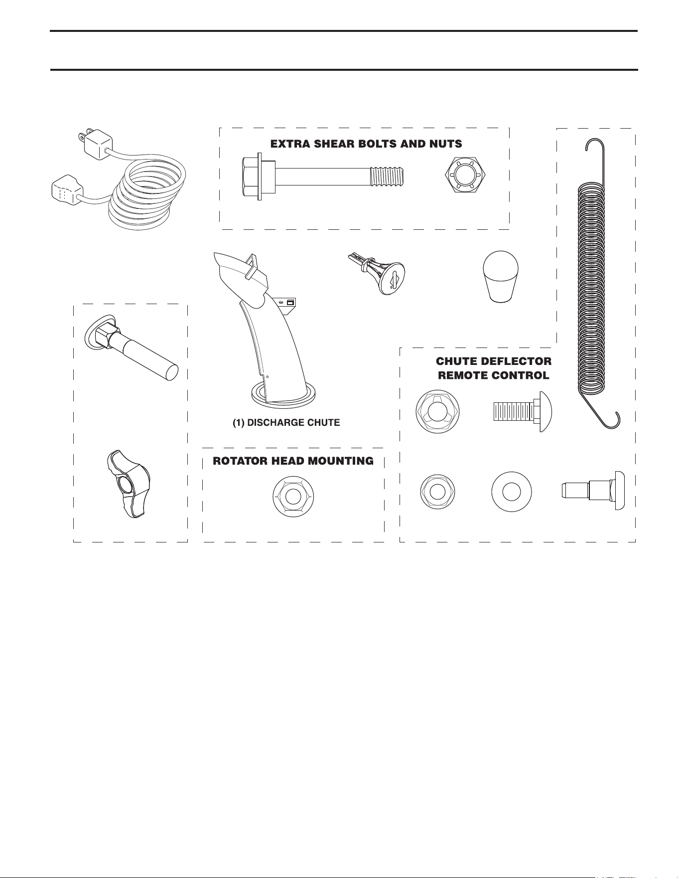
PARTS PACKED SEPARATELY IN CARTON
(1) LOCKNUT
5/16-18
(1) CARRIAGE BOLT
5/16-18 x 5/8
(1) LOCKNUT
1/4-20
(1) SHOULDER
BOLT 1/4-20
(1) SPRING
(2) SHEAR BOLTS 1/4-20 x 1-3/4
(2) LOCKNUTS
1/4-20
(1) LOCKNUT 3/8
(3) KNOB
SAFTEY IGNITION KEY (S)
(2) CARRIAGE BOLTS
5/16-18 x 2 1/4”
(2) HANDLE KNOBS
(1) POWER CORD
(1) NYLON
WASHER
6
ASSEMBLY / PRE-OPERATION
Read these instructions and this manual in its entirety before you attempt to assemble or operate your new snow
thrower. Reading the entire manual will familiarize you with the unit, which will assist you in assembly, operation
and maintenance of the product.
Your new snow thrower has been as sem bled at the factory with the ex cep tion of those parts left unassembled for shipping
purposes. All parts such as nuts, washers, bolts, etc., necessary to com plete the as sem bly have been placed in the parts
bag. To ensure safe and proper operation of your snow thrower, all parts and hard ware you assemble must be tightened
se cure ly. Use the correct tools as nec es sary to ensure proper tightness.
FIG. 1
REMOVE SNOW THROWER FROM CAR TON
1. Remove all accessible loose parts and parts boxes
from carton.
2. Cut down all four corners of carton and lay panels flat.
3. Remove the two (2) screws securing the auger housing
to the pallet and remove additional steel brackets from
skid plate if equipped.
4. Remove all packing materials.
5. Remove plastic ties securing the snow thrower to the
pallet.
6. Remove snow thrower from carton and check carton
thor ough ly for ad di tion al loose parts.
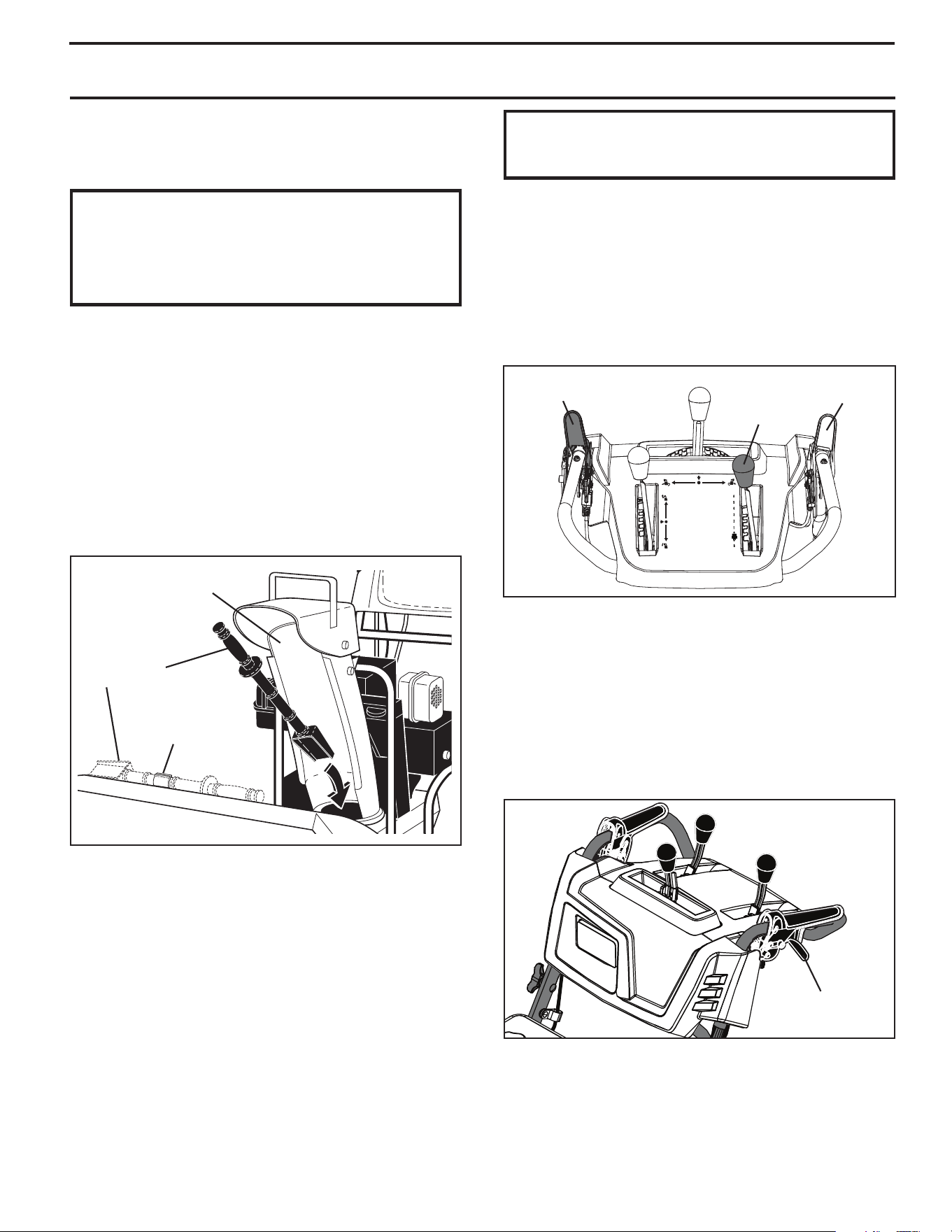
HOW TO SET UP YOUR SNOW THROWER
Store the extra shear bolts and nuts provided in parts bag.
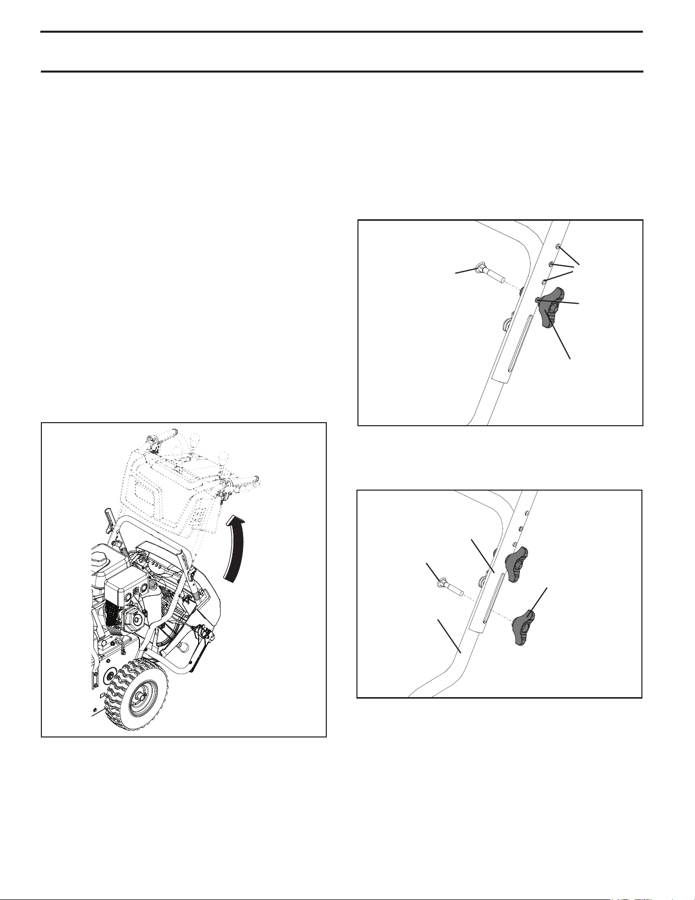
UNFOLD UPPER HANDLE (See Figs. 1-3)
1. Raise upper handle to the operating position.
2. Adjust the handle height to desired position using the
appropriate mounting holes and tighten lower handle
knobs securely.
3. Install the additional carriage bolts and handle knobs
that are supplied in the bag of parts to secure upper
handle to lower handle.
HANDLE
KNOB
LOWER
HANDLE
CARRIAGE
BOLT
UPPER
HANDLE
FIG. 3
HANDLE
KNOB
MOUNTING
HOLES
MOUNTING
BOLT
FIG. 2
CARRIAGE
BOLT
7
ASSEMBLY / PRE-OPERATION
CHECK TIRE PRESSURE
The tires on your snow thrower were overinflated at the fac-
tory for shipping purposes. Correct and equal tire pres sure
is important for best snow throwing performance.
• Reduce tire pressure to 14-17 PSI.
CONTROL LEVER
KNOB KNOB
FIG. 7
FIG. 4
CHUTE
ROTATOR
HEAD
LOCKNUT
THREADED
STUD
PIN
ROTATOR HEAD
MOUNT ING
BRACKET
CHUTE
BRACKET
ALIGN BEFORE
TIGHTENING LOCKNUT
FIG. 5
ROTATOR
CABLES
ROTATOR
CABLES
DOUBLE
CLIP
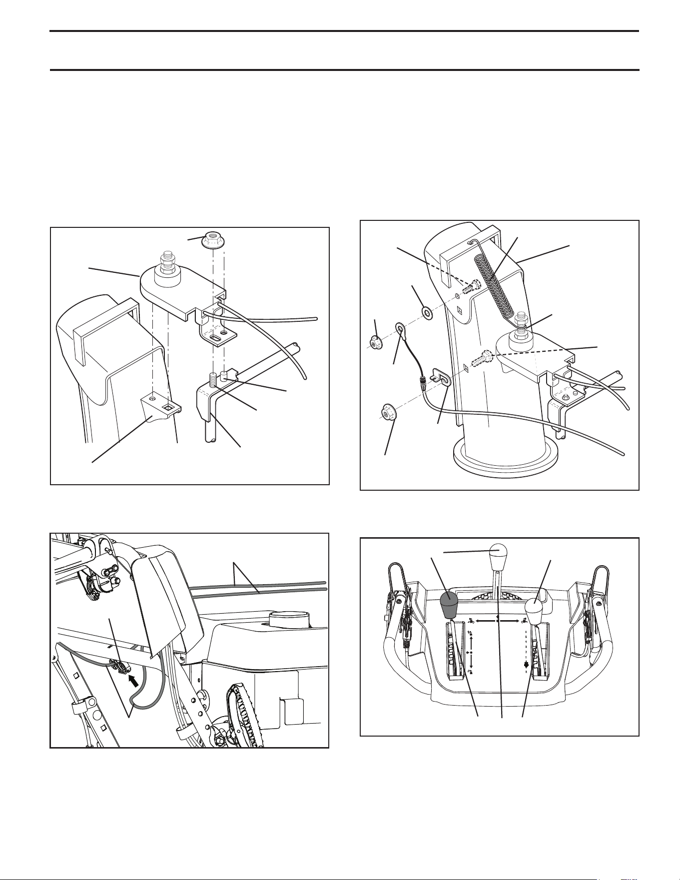
5. Secure cables to the lower handle using the double
clip.
INSTALL DISCHARGE CHUTE / CHUTE ROTATOR HEAD
(See Fig. 4 and 5)
1. Place discharge chute assembly on top of chute base
with discharge opening toward front of snow thrower.
2. Position chute rotator head over chute bracket. If nec es-
sary, rotate chute assembly to align square and pin on un-
der side of chute rotator head with holes in chute brack et.
3. With chute rotator head and chute bracket aligned,
po si tion chute rotator head on pin and threaded stud
of mounting bracket.
4. Install locknut on threaded stud and tighten securely.
INSTALL CHUTE DEFLECTOR REMOTE CONTROL
(See Figs. 6 and 7)
1. Install remote cable bracket to discharge chute with
5/16-18 carriage bolt and 5/16-18 locknut as shown.
Tighten securely.
2. Install remote cable eyelet to chute deflector with
1/4-20 shoulder bolt, nylon washer and 1/4-20 locknut
as shown. Tighten nut securely. Eyelet will be loose
on shoulder bolt.
3. Install spring hooks between hex nuts on chute rotator
head and into hole in chute deflector as shown.
4. Install all control lever knobs by pressing them down
onto the control levers.
FIG. 6
HOOK
BE TWEEN
HEX NUTS
ON CHUTE
ROTATOR
HEAD
SPRING
CHUTE
DE FLEC TOR
5/16-18
CARRIAGE
BOLT
5/16-18
LOCKNUT
REMOTE
CABLE
BRACKET
1/4-20
LOCK NUT
CABLE
EYELET
1/4-20
SHOULDER
BOLT
NYLON
WASHER
8
OPERATION
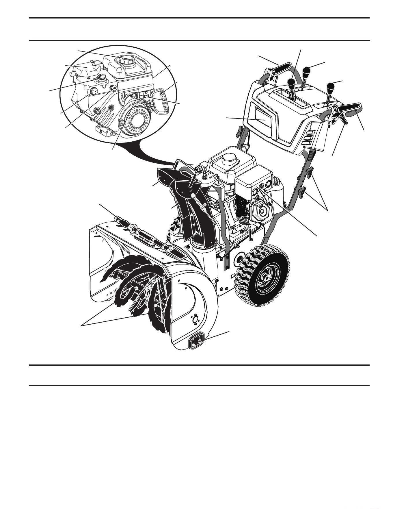
KNOW YOUR SNOW THROWER
READ THIS OWNER'S MANUAL AND ALL SAFETY RULES BEFORE OPERATING YOUR SNOW THROWER. Compare
the illustrations with your snow thrower to familiarize yourself with the location of various controls and adjustments. Save
this manual for future reference.
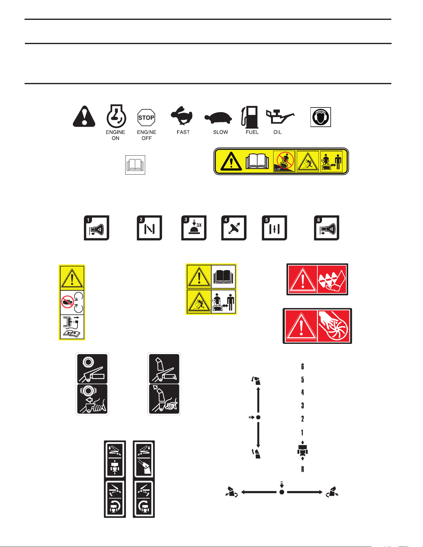
These symbols may appear on your snow thrower or in literature supplied with the product. Learn and understand
their meaning.
READ AND FOLLOW ALL SAFETY INFORMATION
AND INSTRUCTIONS BEFORE USE OF THIS PRODUCT.
KEEP THESE INSTRUCTIONS FOR FUTURE REFERENCE.
EAR PROTECTION
RECOMMENDED
DANGER
OR WARNING
SNOW
DISCHARGE
TRACTION
DRIVE CONTROL
DISENGAGED
ENGAGED
ROTATE LEFT ROTATE RIGHT
CHUTE
ROTATION
IGNITION KEY. INSERT
TO START AND RUN
CHOKE CLOSED
(START)
RECOIL START
CHOKE OPEN
(RUN)
PRIMER
IGNITION KEY. PULL
OUT TO STOP
UP
CHUTE
DEFLECTOR
DOWN
FORWARD
REVERSE
DANGER, KEEP FEET AWAY
DANGER, KEEP HANDS AWAY
READ OPERATORS MANUAL
DANGER
DO NOT OPERATE ON STEEP SLOPES
WATCH FOR THROWN OBJECTS
OPERATE AT A SAFE DISTANCE FOR OTHER PEOPLE
DO NOT PLACE HANDS
NEAR BLADES
DANGER
REMOVE SPARK
PLUG WIRE BEFORE
PERFORMING
MAINTENANCE
READ OPERATORS MANUAL
DANGER
WATCH FOR THROWN OBJECTS
OPERATE AT A SAFE DISTANCE FROM OTHER PEOPLE
STEER LEFT STEER RIGHT
TRACTION
DRIVE CONTROL
SNOW
DISCHARGE
9
ELECTRIC
START
BUTTON
RECOIL
STARTER
HANDLE
ON / OFF
SWITCH
SAFETY
IGNITION
KEY
PRIM ER
CHOKE
CON TROL
MUF FLER
GAS O LINE
FILLER CAP
THROTTLE
MEETS A.N.S.I. SAFETY REQUIREMENTS
Our snow throwers conform to the standards of the American National Standards Institute.
FIG. 8
OPERATION
LH and RH turn triggers - used to steer the snow thrower.
Traction drive control lever - used to engage power-
pro pelled for ward or reverse motion of snow thrower.
Auger control lever - used to engage auger motion (throw
snow).
Discharge chute control lever - used to change the di rec-
tion the snow is thrown.
Deflector remote control lever - used to change the
dis tance the snow is thrown.
Skid plate - used to adjust height of scraper bar from the
ground.
Safety ignition key - must be inserted for the engine to
start and run. Remove when snow thrower is not in use.
Electric start button - used for starting the engine.
Recoil starter handle - used for start ing en gine.
Primer - pumps additional fuel from the carburetor to the
cylinder for use when starting a cold engine.
Choke Control - used for starting a cold engine.
ON / OFF switch - used to STOP the engine.
Throttle- used to se lect FAST or SLOW engine speeds.
Drive speed control lever - used to select forward or
reverse motion and speed of snow thrower.
DEFLECTOR
REMOTE
CONTROL
LEVER
TRACTION
DRIVE
CONTROL
LEVER
DISCHARGE CHUTE CONTROL LEVER
DRIVE SPEED
CON TROL LEVER
AUGER
CONTROL
LEVER
MUF FLER
HANDLE KNOB
SKID PLATE
CHUTE
DE FLEC TOR
DISCHARGE
CHUTE
AU GERS
NOTE: ITEMS ABOVE
ARE SHOWN IN
THEIR TYPICAL
LOCATION ON THE
ENGINE. ACTUAL
LOCATION MAY
VARY WITH THE
ENGINE ON YOUR
UNIT.
CLEAN-OUT
TOOL
LH TURN
TRIGGER
LIGHT
10
OPERATION
TO CONTROL SNOW DISCHARGE (See Fig. 11)
WARNING: Snow throwers have ex-
posed rotating parts, which can cause
severe injury from contact, or from ma-
terial thrown from the discharge chute.
Keep the area of operation clear of all
persons, small children and pets at all
times including startup.
WARNING: If the discharge chute or
au ger become clogged, shut-off en gine
and wait for all moving parts to stop. Use
the clean-out tool, NOT YOUR HANDS,
to un clog the chute and/or auger.
FIG. 11
DISCHARGE CHUTE
CONTROL LEVER
CHUTE DEFLECTOR
REMOTE CONTROL
LEVER
TO THROW SNOW (See Fig. 12)
The auger rotation is controlled by the auger control lever
located on the right side handle.
• Squeeze auger control lever to handle to engage the
auger and throw snow.
• Release the auger control lever to stop throwing snow.
AUGER
CONTROL
LEVER
FIG. 12
The DIRECTION in which snow is to be thrown is controlled
by the discharge chute control lever.
• To change the discharge chute position, pull backward
on discharge chute control lever and move lever left
or right until chute is in desired position. Be sure lever
springs back and locks into desired position.
The DISTANCE that snow is thrown is controlled by the
position of the chute deflector. Set the deflector low to
throw snow a short distance; set the deflector higher to
throw snow farther.
• Push right on chute deflector control lever and move
lever forward to lower the deflector and decrease the
distance. Move lever back to raise the deflector and
increase the distance. Be sure lever springs back and
locks into desired position.
FIG. 9
FULLOFF
TO USE CHOKE CON TROL (See Fig. 9)
The choke con trol is located on the en gine. Use the choke
control when ev er you are starting a cold en gine. Do not
use to start a warm en gine.
• To engage choke, turn knob counterclockwise. Slowly
turn knob clockwise to disengage.
TO USE THROTTLE CONTROL (See Fig. 10)
The throttle control is located on the engine. Always op er ate
the snow thrower with the engine at full throttle. Full throttle
offers the best snow thrower performance.
FIG. 10
SLOW FAST
The operation of any snow thrower can result
in foreign objects thrown into the eyes, which
can result in severe eye damage. Always wear
safety glasses or eye shields while operating
your snow thrower or performing any ad just-
ments or repairs. We recommend standard safe ty glasses
or a wide vision safety mask worn over spectacles.
HOW TO USE YOUR SNOW THROWER
Know how to operate all controls before adding fuel or
attempting to start the engine.
STOPPING
TRACTION DRIVE
• Release traction drive control lever to stop the forward
or reverse movement of the snow thrower.
AUGER
• Release the auger control lever to stop throwing snow.
ENGINE
1. Move ON / OFF switch to “OFF” position.
2. Remove (do not turn) safety ignition key to prevent
unauthorized use.
NOTE: Never use choke to stop engine.
11
TO MOVE FORWARD AND BACKWARD (See Fig. 14)
SELF-PROPELLING, forward and reverse movement of
the snow thrower, is controlled by the traction drive control
lever located on the left side handle.
• Squeeze traction drive control lever to handle to en gage
the drive system.
• Release traction drive control lever to stop the forward
or reverse movement of the snow thrower.
SPEED and DIRECTION are controlled by the drive speed
control lever.
• Push right on the speed control lever and move lever to
de sired po si tion BE FORE engaging the trac tion drive
control lever. Be sure lever springs back and locks into
desired position.
OPERATION
USING THE CLEAN-OUT TOOL (See Fig. 13)
In certain snow conditions, the discharge chute may
become clogged with ice and snow. Use the clean-out tool
to dislodge this blockage.
When cleaning, repairing, or in spect ing, make
certain all controls are disengaged and the
auger/impeller and all moving parts have
stopped. Disconnect the spark plug wire and
keep the wire away from the spark plug to
prevent accidental starting.
• Release the auger control lever and shut off the engine.
• Remove the clean-out tool from its mounting clip.
Grasp the tool firmly by the handle while pushing and
twisting the tool into the discharge chute to dislodge
the blockage.
After the packed snow has been dislodged, return the
clean-out tool to it's mounting clip by pushing it into the clip.
• Make sure the discharge chute is pointed in a safe
direction (no vehicles, buildings, people, or other objects
are in the direction of discharge) before restarting engine.
• Restart the engine, then squeeze the auger control lever
to the handle to clear snow from the auger housing and
the discharge chute.
CLEAN-OUT
TOOL
FIG. 13
MOUNTING
CLIP
DISCHARGE CHUTE
DRIVE
SPEED
CONTROL
LEVER
TRACTION DRIVE
CONTROL LEVER
FIG. 14
AUGER
CONTROL
LEVER
POWER STEERING OPERATION (See Fig. 15)
Steering triggers are used to assist in steering your snow
thrower. The triggers are located on the underside of each
handle. When a trigger is squeezed, it disengages the drive
wheel on that side of snow thrower and allows it to turn in
that direction.
• To turn left – squeeze left side trigger.
• To turn right – squeeze right side trigger.
FIG. 15
CAUTION: Do not move speed con trol le ver
when traction drive control lever is en gaged.
Damage to the snow thrower can result.
• Slower speeds are for heavier snow and faster speeds
are for light snow and transporting the snow thrower. It
is recommended that you use a slower speed until you
are familiar with the operation of the snow thrower.
NOTE: When both traction drive and auger control levers
are engaged, the traction drive control lever will lock the
auger control lever in the engaged position. This will allow
you to release your right hand from the handle and adjust
the discharge chute direction without interrupting the snow
throwing process.
LH TURN
TRIGGER
12
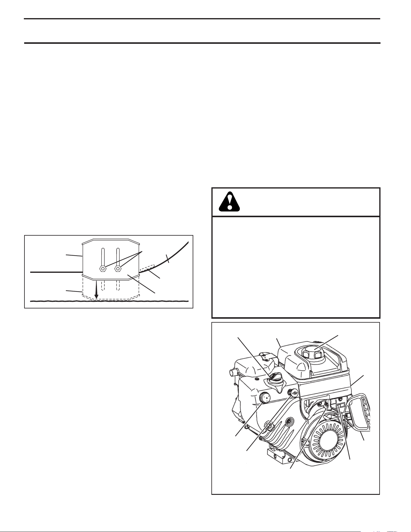
TO ADJUST SKID PLATES (See Fig. 16)
NOTE: The wrench provided in your parts bag may be
used to adjust the skid plates.
Skid plates are located on each side of the auger housing
and adjust the clearance between the scraper bar and the
ground surface. Adjust skid plates evenly to proper height
for current surface conditions. For removal of snow in
normal con di tions, such as a paved driveway or side walk,
place skid plates in the highest position (lowest scraper
clear ance) to give a 1/8" clearance between the scraper
bar and the ground. Use a middle position if the surface
to be cleared is uneven.
NOTE: It is not recommended to operate the snow thrower
over gravel or rocky surfaces. Objects such as gravel, rocks
or other debris, can easily be picked up and thrown by the
impeller, which can cause serious personal injury, property
dam age or damage to the snow thrower.
• If snow thrower must be operated over gravel surface,
use extra caution and be sure skid plates are adjusted
to lowest (highest scraper clear ance) position.
1. Shut off engine and wait for all moving parts to stop.
2. Adjust skid plates by loosening the 1/2" hex nuts, then
moving skid plate to desired position. Be sure both
plates are adjusted evenly. Tighten securely.
OPERATION
BEFORE STARTING THE ENGINE
CHECK ENGINE OIL LEVEL (See Fig. 17)
The engine on your snow thrower has been shipped from
the factory already filled with oil.
1. Check engine oil with snow thrower on level ground.
2. Remove oil fill cap/dipstick and wipe clean, reinsert
the dipstick and screw tight, wait for a few seconds,
remove and read oil level. If necessary, add oil until
“FULL” mark on dipstick is reached. Do not overfill.
• To change engine oil, see “TO CHANGE ENGINE OIL”
in the Main te nance sec tion of this manual.
ADD GASOLINE (See Fig. 17)
• Fill fuel tank to bottom of tank filler neck. Do not over-
fill. Use fresh, clean, regular unleaded gasoline with
a minimum of 87 octane. Do not mix oil with gasoline.
Purchase fuel in quan ti ties that can be used within 30
days to assure fuel freshness.
WARNING: Wipe off any spilled oil or
fuel. Do not store, spill or use gasoline
near an open flame.
CAUTION: Alcohol blended fuels (called gas o-
hol or using ethanol or methanol) can attract
moisture which leads to separation and for ma-
tion of acids dur ing storage. Acidic gas can
damage the fuel system of an engine while in
storage. To avoid engine problems, the fuel
system should be emptied be fore stor age of
30 days or longer. Drain the gas tank, start
the engine and let it run until the fuel lines
and carburetor are empty. Use fresh fuel next
season. See Storage In struc tions for ad di tion al
information. Never use engine or car bu re tor
cleaner products in the fuel tank or per ma nent
damage may occur.
SCRAPER BAR (See Fig. 16)
The scraper bar is not adjustable, but is reversible. After
con sid er able use it may become worn. When it has worn
almost to the edge of the housing, it can be reversed,
providing additional service before requiring replacement.
Replace a dam aged or worn scrap er bar.
SKID PLATE
LOW POSITION
(HIGH GROUND
CLEAR ANCE)
HEX
NUTS
HIGH POSITION
(LOW GROUND
CLEARANCE)
AUGER
HOUSING
FIG. 16
SCRAPER
BAR
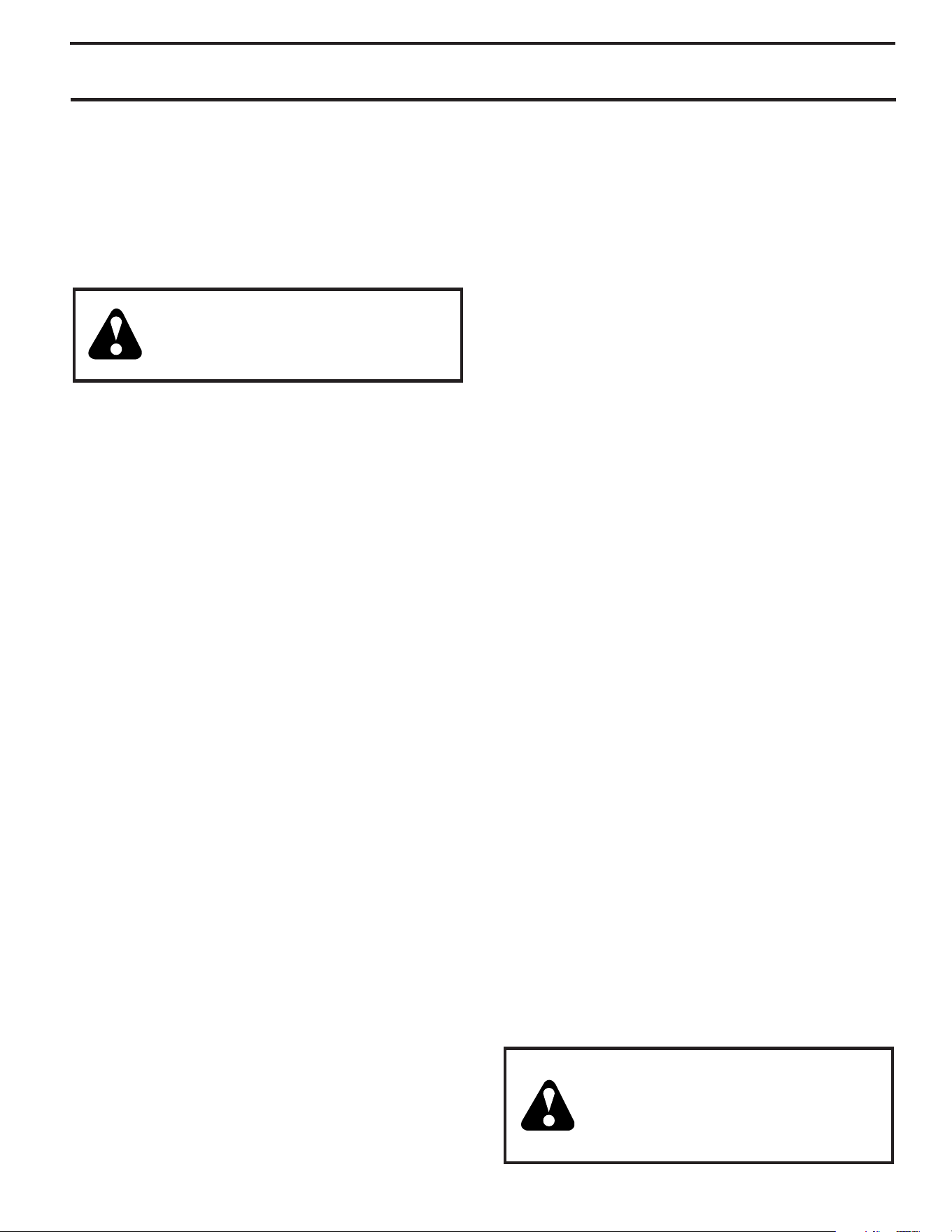
ENGINE OIL
FILL CAP / DIPSTICK
PRIM ER
SAFETY
IG NI TION
KEY
ON / OFF
SWITCH
STARTER
BUTTON
RECOIL
STARTER
HANDLE
GAS O LINE
FILLER CAP
NOTE: ALL ITEMS ARE SHOWN IN THEIR TYPICAL LOCATION.
ACTUAL LOCATION MAY VARY WITH ENGINE ON YOUR UNIT.
FIG. 17
CHOKE
CONTROL
THROT TLE
13
OPERATION
SNOW THROWING TIPS
• Always operate the snow thrower with the engine at
full throttle. Full throttle offers the best performance.
• Go slower in deep, freezing or heavy wet snow. Use the
drive speed control, NOT the throttle, to adjust speed.
• It is easier and more efficient to remove snow im me-
di ate ly after it falls.
• The best time to remove snow is the early morning.
At this time the snow is usually dry and has not been
exposed to the direct sun and warming tem per a tures.
• Slightly overlap each successive path to ensure all
snow will be removed.
• Throw snow downwind whenever possible.
• Ad just the skid plates to proper height for current snow
con di tions. See “TO ADJUST SKID PLATES” in this
section of this manual.
• For extremely heavy snow, re duce the width of snow
removal by over lap ping previous path and moving
slowly.
• Keep engine clean and clear of snow during use. This
will help air flow and extend engine life.
• After snow-throwing is completed, allow engine to run
for a few minutes to melt snow and ice off the engine.
• Clean the entire snow thrower thoroughly after each
use and wipe dry so it is ready for next use.
WARNING: Do not operate snow
thrower if weather conditions im pair
visibility. Throwing snow dur ing a
heavy, windy snowstorm can blind
you and be hazardous to the safe
operation of the snow thrower.
TO START ENGINE
Your snow thrower engine is equipped with both a 120 Volt
A.C. electric starter and a recoil starter. The electric starter
is equipped with a three-wire power plug and is designed
to operate on 120 Volt A.C. household current.
• Ensure your house is a 120 Volt A.C. three-wire
ground ed system. If you are uncertain, consult a
li censed electrician.
NOTE: Use an extension cord recommended for outdoor
use that is not longer than 50 feet (15 m).
WARNING: Do not use the electric
start er if your house is not a 120 Volt A.C.
three-wire grounded system. Se ri ous
per son al injury or damage to your snow
thrower could result.
COLD START - ELECTRIC STARTER
1. Insert safety ignition key (tied to recoil start cord) into
ignition slot until it clicks. DO NOT turn the key. Keep
the extra safety ignition key in a safe place.
2. Place throttle control in “FAST” position.
3. Place ON / OFF switch in “ON” position.
4. Rotate choke control to “FULL” position.
5. Push the primer three (3) times.
NOTE: Over priming may cause flooding, preventing the
engine from starting. If you do flood the engine, wait a few
minutes be fore at tempt ing to start and DO NOT push the
primer.
6. Connect the extension cord to the engine.
7. Plug the other end of the extension cord into a three-
hole grounded 120 Volt A.C. receptacle.
8. Push starter button until engine starts.
IMPORTANT: Do not crank engine more than five con tin u-
ous seconds between each time you try to start. Wait 5 to
10 seconds between each attempt.
9. When the engine starts, release the starter button and
slowly move the choke control to the “OFF” position.
10. Disconnect the extension cord from the receptacle first,
then from the engine.
Allow the engine to warm up for a few minutes. Engine will
not develop full power until it has reached normal operating
temperature.
WARM START - ELECTRIC STARTER
Follow the steps above, keeping the choke control in the
“OFF” position.
COLD START - RECOIL STARTER
1. Insert safety ignition key (tied to recoil start cord) into
ignition slot until it clicks. DO NOT turn the key. Keep
the extra safety ignition key in a safe place.
2. Place throttle control in “FAST” position.
3. Place ON / OFF switch in “ON” position.
4. Rotate choke control to “FULL” position.
5. Push the primer three (3) times.
NOTE: Over priming may cause flooding, preventing the
engine from starting. If you do flood the engine, wait a few
minutes be fore at tempt ing to start and DO NOT push the
primer.
6. Pull recoil starter handle quickly. Do not allow starter
rope to snap back.
7. When the engine starts, release the recoil starter
han dle and slowly move the choke control to the “OFF”
position.
Allow the engine to warm up for a few minutes. Engine will
not develop full power until it has reached normal operating
temperature.
WARM START - RECOIL STARTER
Follow the steps above, keeping the choke in the “OFF”
position. DO NOT push the primer.
BEFORE STOPPING
Run the engine for a few minutes to help dry off any moisture
on the engine.
IF RECOIL STARTER HAS FROZEN
If the recoil starter has frozen and will not turn the engine,
proceed as follows:
1. Grasp the recoil starter handle and slowly pull as much
rope out of the starter as possible.
2. Release the recoil starter handle and let it snap back
against the starter.
If the engine still fails to start, repeat the above steps or
use the electric starter.
14
MAINTENANCE
LUBRICATION CHART
GENERAL REC OM MEN DA TIONS
The warranty on this snow thrower does not cover items
that have been sub ject ed to operator abuse or negligence.
To receive full value from the warranty, operator must
maintain snow thrower as in struct ed in this manual. Some
ad just ments will need to be made periodically to properly
maintain your snow thrower.
All adjustments in the Service and Ad just ments section of
this manual should be checked at least once each season.
• Once a year, you should replace the spark plug and
check belts for wear. A new spark plug will help your
engine run better and last longer.
• Follow the maintenance schedule in this manual.
NOTE: Use only Original Equipment Manufacturer (OEM)
parts to service this unit. Failure to do so can cause the
unit to malfunction and pose a risk of injury to the operator.
BEFORE EACH USE
1. Check engine oil level.
2. Check for loose fasteners.
3. Check controls to be sure they are functioning properly.
LUBRICATION
Keep your snow thrower well lubricated
(See “LU BRI CA TION CHART”).
At the beginning of each season, or every 25 hours of
use, apply a small amount of white lithium grease to the
interlock bosses.
➀
SAE 5w30 Motor Oil
➁
See “Engine” in Maintenance section
➂
White Lithium Grease
Engine oil
Pivot points
➂
Interlock
bosses
15
CLEANING
IMPORTANT: For best performance, keep snow thrower
housing free of any dirt or trash. Clean the outside of your
snow thrower after each use.
WARNING: Remove safety ignition key
and disconnect spark plug wire from
spark plug. Place wire where it can not
come in contact with spark plug.
• Keep finished surfaces/wheels free of gasoline, oil, etc.
• We do not recommend using a garden hose to clean
your snow thrower unless the electrical system, muffler
and carburetor are covered to keep water out. Water
in engine can result in shortened engine life.
MAINTENANCE
BELTS
Check belts for deterioration and wear after every 50 hours
of operation and replace if necessary. The belts are not
ad just able. Replace belts if they begin to slip from wear.
(See “TO REMOVE BELT COVER” in the Service and
Adjustments section of this manual).
The belts on your snow thrower are of special con struc tion
and should be replaced by original equipment man u fac tur er
(OEM) belts avail able from your nearest dealer. Using other
than OEM belts can cause personal injury or damage to
the snow thrower.
SNOW THROWER
Always observe the safety rules when performing any
main te nance.
TIRES
• Maintain proper air pressure in both tires (14–17 PSI).
• Keep tires free of gasoline and oil, which can harm rubber.
NOTE: To seal tire punctures and prevent flat tires due
to slow leaks, tire sealant may be purchased from your
local parts dealer. Tire sealant also prevents tire dry rot
and cor ro sion.
AUGER GEAR CASE
• The gear case was filled with lubricant to the proper level
at the factory. The only time the lubricant needs atten-
tion is if service has been performed on the gear case.
• If lubricant is required, use only Ronex ED #1 grease.
TRACTION DRIVE SYSTEM
DO NOT lubricate the drive components inside the snow
thrower. The sprockets, hex shafts, drive disc and friction
wheel require no lubrication. The bearings and bushings
are lifetime lubricated and require no maintenance.
CAUTION: Any lubricating of the above com po-
nents can cause contamination of the friction
wheel and damage to the drive system of your
snow thrower.
ENGINE
See engine manual.
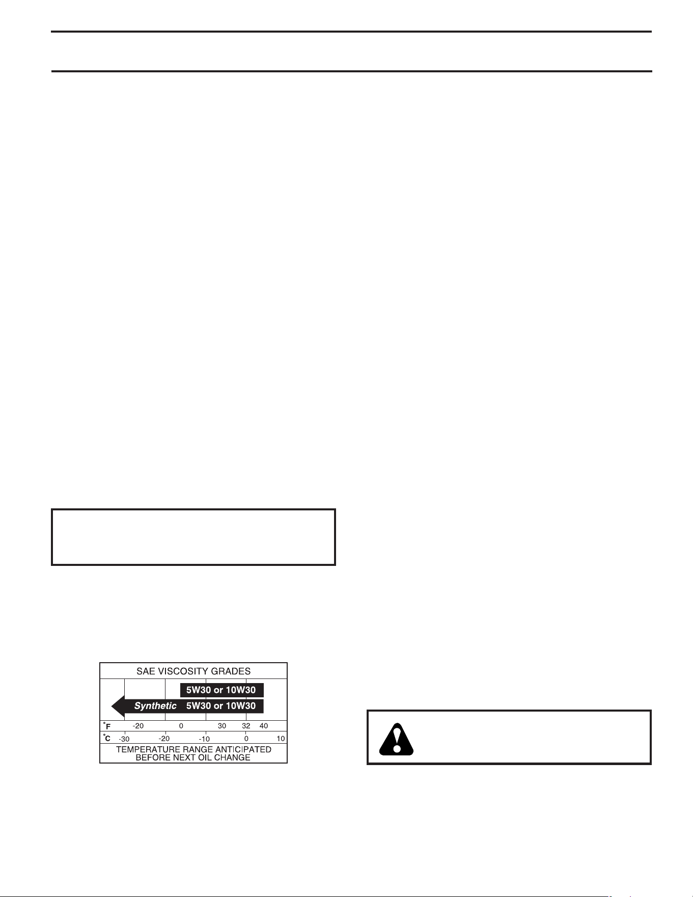
LUBRICATION
Use only high quality detergent oil rated with API service
classification SG–SL. Select the oil's SAE viscosity grade
according to your expected operating temperature.
NOTE: Although multi-viscosity oils (5W30, 10W30 etc.)
improve starting in cold weather, these multi-viscosity oils
will result in increased oil consumption when used above
32°F. Check your engine oil level more frequently to avoid
possible engine damage from running low on oil.
Change the oil after every 25 hours of operation or at least once
a year if the snow thrower is not used for 25 hours in one year.
MUFFLER
Inspect and replace corroded muffler as it could cre ate a
fire haz ard and/or dam age.
SPARK PLUG
Replace spark plug at the beginning of each season or after
every 100 hours of operation, whichever occurs first. Spark
plug type and gap setting are shown in the “PROD UCT
SPEC I FI CA TIONS” section of this manual.
Check the crankcase oil level before starting the engine
and after each five (5) hours of continuous use. Tighten oil
fill cap / dipstick securely each time you check the oil level.
TO CHANGE ENGINE OIL
Determine temperature range anticipated before next oil
change. All oil must meet API service classification SG–SL.
• Be sure snow thrower is on level surface.
• Oil will drain more freely when warm.
• Catch oil in a suitable container.
NOTE: A wheel may be removed from snow thrower for
easier access to the oil drain plug and place ment of a
suitable container.
1. Remove safety ignition key and disconnect spark plug
wire from spark plug. Place wire where it cannot come
in contact with spark plug.
2. Clean area around drain plug.
3. Remove drain plug and drain oil in a suitable container.
4. Install drain plug and tighten securely.
5. Wipe off any spilled oil from snow thrower and engine.
6. Install left wheel (if removed for draining oil). Be sure
to install wheel pin and retainer pin into proper hole
in wheel axle (See “TO REMOVE WHEELS” in the
Service and Adjustments section of this manual).
7. Remove oil fill cap/dipstick. Be careful not to allow dirt
to enter the engine.
8. Refill engine with oil through oil dipstick tube. Pour
slowly. Do not overfill. For approximate capacity see
“PRODUCT SPECIFICATIONS” section of this man u al.
9. Use gauge on oil fill cap/dipstick for checking level.
Be sure dipstick cap is tightened securely for accurate
reading. Keep oil at “FULL” line on dipstick.
10. Wipe off any spilled oil.
16
SERVICE AND ADJUSTMENTS
WARNING: To avoid serious injury, before
performing any service or ad just ments:
1. Be sure the on/off switch is in the
OFF position.
2. Remove safety ignition key.
3. Make sure the augers and all mov ing
parts have completely stopped.
4. Disconnect spark plug wire from
spark plug and place wire where it
can not come in contact with plug.
SNOW THROWER
TO ADJUST SNOW THROWER HEIGHT
See “TO ADJUST SKID PLATES” and “SCRAPER BAR”
in the Operation section of this manual.
CHUTE DEFLECTOR
The chute deflector, attached to the top of the discharge
chute, is provided to direct discharging snow away from
the operator. If the deflector becomes damaged, it should
be re placed.
WARNING: To avoid serious injury,
nev er operate your snow thrower with
the deflector removed or damaged.
• To change direction and/or distance snow is dis charged,
see “TO CONTROL SNOW DISCHARGE” in the Op-
er a tion section of this manual.
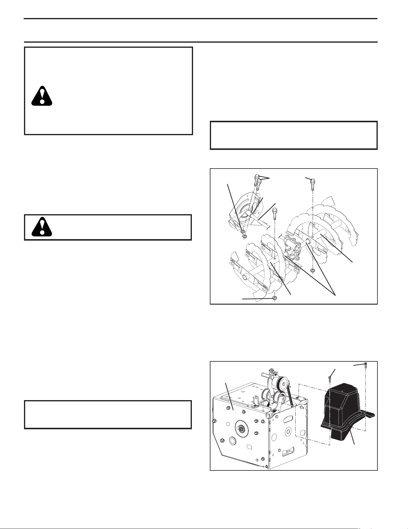
SHEAR BOLTS (See Fig. 18)
AUGER SHEAR BOLTS
Both right and left-hand augers are secured to the auger
shaft with a shear bolt and hex nut. Should a foreign ob-
ject or ice become lodged in the augers, the shear bolts
are designed to break, preventing damage to any other
com po nents. If one or both augers do not turn when auger
control lever is engaged, check to see if one or both of the
bolts have sheared. To replace the shear bolts:
1. Disengage all controls and move throttle control to
STOP position. Wait for all moving parts to stop.
2. Remove safety ignition key and disconnect spark plug
wire from spark plug. Place wire where it cannot come
in contact with spark plug.
3. Align hole in auger hub with hole in auger shaft and
install a new 1/4-20 x 2" shear bolt. Install 1/4-20
lock nut and tighten securely.
CAUTION: Do not sub sti tute. Use only original
equip ment shear bolts as sup plied with your
snow thrower.
4. Insert safety ignition key and reconnect spark plug wire
to spark plug.
IMPELLER SHEAR BOLTS
The impeller is secured to the impeller shaft with two (2)
shear bolts and hex nuts. Should a foreign object or ice
become lodged in the impeller, the shear bolts are de signed
to break, preventing damage to any other com po nents. If
impeller does not turn when auger control lever is engaged,
check to see if the shear bolts have sheared.
AUGER SHAFT
1/4-20 x 2
SHOULDER /
SHEAR BOLT
1/4-20
LOCK NUT
IMPELLER
SHAFT
1/4-20
LOCKNUT
IMPELLER HUB
AUGER
HUB
AUGER HUB
FIG. 18
To replace the shear bolts:
1. Disengage all controls and move throttle control to
STOP position. Wait for all moving parts to stop.
2. Remove safety ignition key and disconnect spark plug
wire from spark plug. Place wire where it cannot come
in contact with spark plug.
3. Align holes in impeller hub with holes in impeller shaft
and install two (2) new 2" shear bolts. Install 1/4-20
locknuts and tighten securely.
CAUTION: Do not substitute. Use only original
equip ment capscrew/shear bolts as sup plied
with your snow thrower.
4. Insert safety ignition key and reconnect spark plug wire
to spark plug.
TO REMOVE BELT COVER (See Fig. 19)
1. Loosen the two (2) screws securing belt cover to frame.
2. Remove belt cover.
• Replace belt cover by installing cover and tightening
screws.
BELT
COVER
SCREWS
FRAME
FIG. 19
17
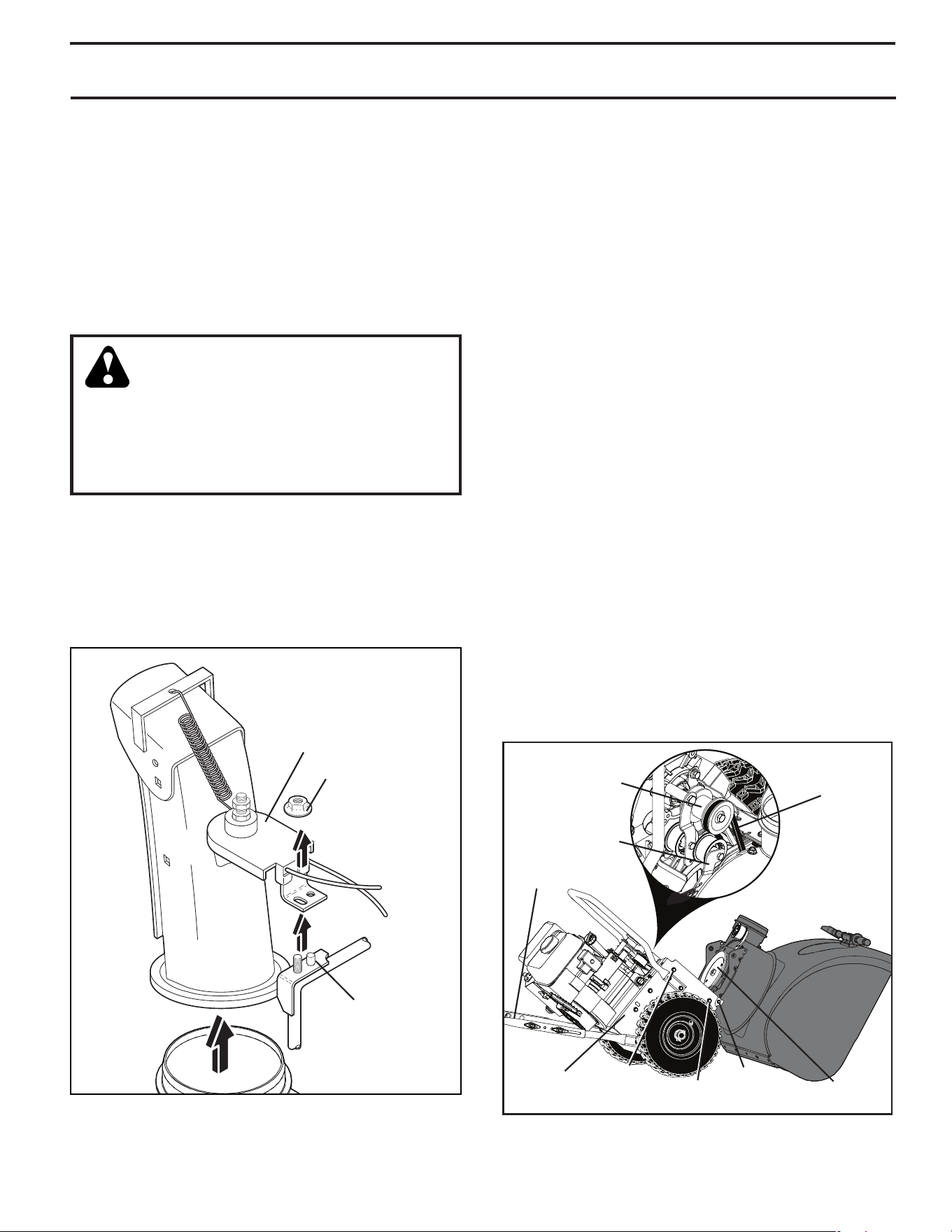
SERVICE AND ADJUSTMENTS
FIG. 20
LOCK NUT
MOUNTING
BRACKET
CHUTE ROTATOR HEAD
TO REPLACE BELTS
The auger and traction drive belts are not adjustable. If the
belts are damaged or begin to slip from wear, they should
be replaced. It is recommended that the belt(s) be replaced
by a service center/department.
NOTE: It is recommended that both the auger and traction
drive belt be replaced at the same time.
The V-belts on your snow thrower are of special con struc-
tion and should be replaced by original equipment man u-
fac tur er (OEM) belts avail able from your nearest service
center/department. Using other than OEM belts can cause
personal injury or damage to the snow thrower.
WARNING: Belt replacement requires
separation of the snow thrower. While
separating the auger housing from the
frame assembly, it is important that an
assistant stand in the operating po si tion
and hold the snow thrower han dles. Serious
personal injury and/or damage to the unit
could occur if the snow thrower should fall
during the belt chang ing process.
BEFORE REPLACING BELTS
1. REMOVE GASOLINE FROM FUEL TANK - Drain
gasoline from fuel tank into a suitable container, outdoors,
away from fire or flame. Wipe up any spilled gasoline.
2. REMOVE DISCHARGE CHUTE - Remove lock nut
securing chute rotator head to mounting bracket to allow
chute rotator head to be raised and discharge chute to
be removed from snow thrower. See Fig. 20.
3. REMOVE BELT COVER - See “TO REMOVE BELT
COVER” in this section of this manual.
AUGER BELT REPLACEMENT (See Fig. 21)
TO REMOVE AUGER BELT
1. Remove upper 5/16” bolts and lower 1/4” bolts from
both sides of the frame assembly. Do not discard bolts.
2. Loosen but DO NOT REMOVE lower 5/16” bolts on
both sides of the frame assembly.
3. Remove the auger belt from the engine pulley.
4. Tip the back section down. The front section will tip
forward at the same time, as the bottom bolt acts as a
hinge between the front and back sections. Use a block
under the hinge point to secure the snow thrower in the
tipped position as shown.
5. Move auger belt tensioner arm and remove auger belt
from around the arm.
TO INSTALL AUGER BELT
1. Move belt tensioner arm and place auger belt around
and inside groove of the auger pulley.
NOTE: Ensure the belt is not pinched between the frame
and auger housing as you bring the unit back together.
2. Remove block from under the snow thrower. Lift the
handles to tip the back section up. The front section
will tip back and pivot to rejoin the back section.
3. Ensure belt is routed inside auger pulley groove properly.
4. Install the previously removed and loosened 5/16” bolts,
and tighten securely. (8-12 Ft. Lbs. / 11-16 Nm).
Install the previously removed 1/4” bolts, and tighten
securely. (4-6 Ft. Lbs. / 5-8 Nm).
5. Install auger belt onto engine pulley. Ensure belt is
routed correctly around idler pulley and seated properly
in engine pulley groove.
6. Operate all controls to ensure belts are installed properly
and that all components are moving correctly.
Continue with “AFTER REPLACING BELTS” instructions.
FIG. 21
AUGER BELT
TENSIONER ARM
ENGINE PULLEY
AUGER
BELT
LOWER
5/16" BOLT
UPPER
5/16"
BOLT
LOWER
1/4" BOLT
AUGER
PULLEY
HANDLE
FRAME
ASSEMBLY
18
SERVICE AND ADJUSTMENTS
ENGINE
SEE ENGINE MANUAL
CARBURETOR
Your carburetor is not adjustable. Engine performance
should not be affected at altitudes up to 2,134 meters. If
your engine does not operate properly due to suspected
carburetor problems, take your snow thrower to a service
center/department.
ENGINE SPEED
Never tamper with the engine governor, which is factory set
for proper engine speed. Overspeeding the engine above
the factory high speed setting can be dangerous and will
void the warranty. If you think the engine-governed high
speed needs adjusting, contact a service center/depart-
ment, which has the proper equipment and experience to
make any necessary ad just ments.
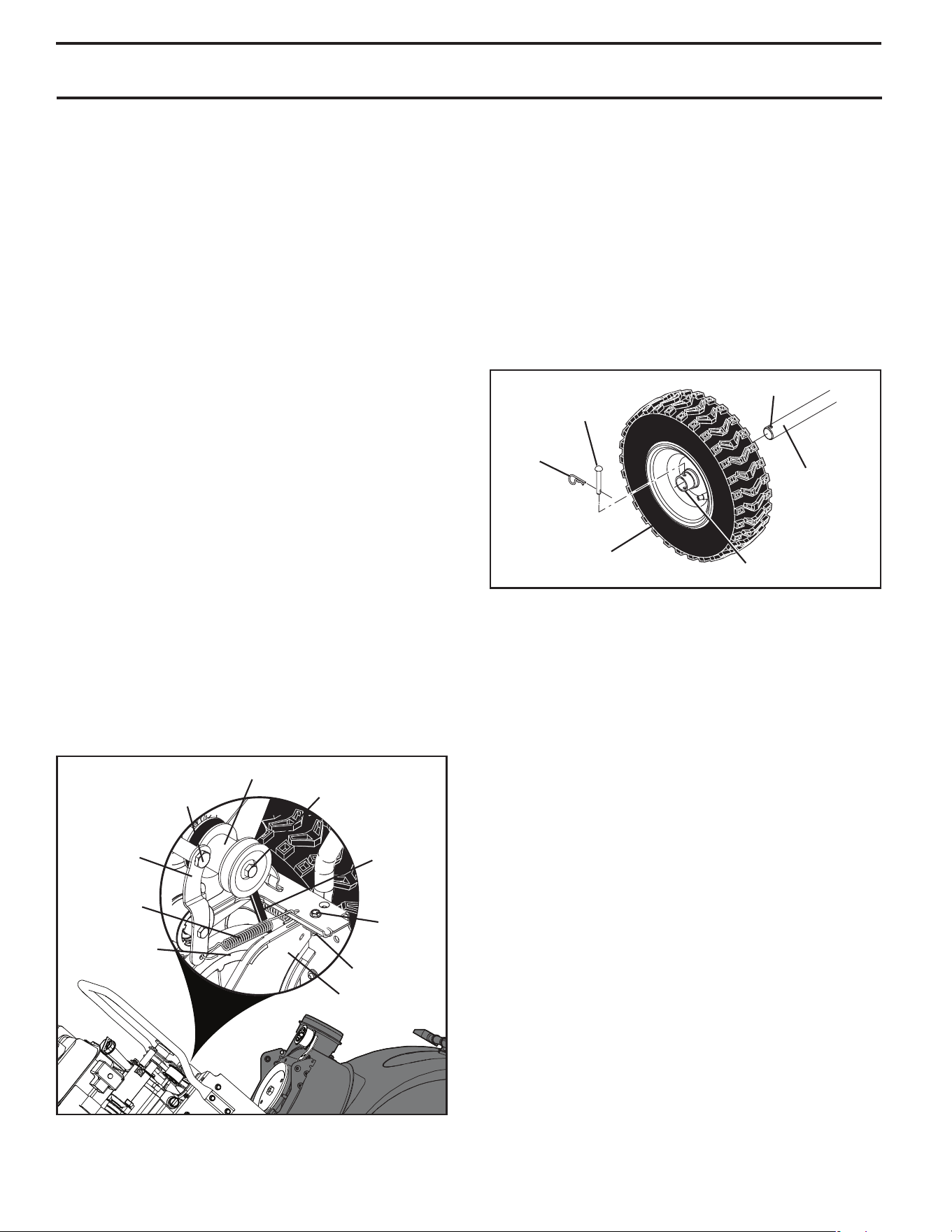
TO REMOVE WHEELS (See Fig. 23)
• Remove the wheel pin and retainer pin and remove
wheel from axle.
NOTE: To seal punctures or prevent flat tires due to slow
leaks, tire sealant may be purchased from your local parts
dealer. Tire sealant also prevents tire dry rot and cor ro sion.
AXLE
OUTER HOLE
WHEEL HUB
WHEEL
RETAINER
PIN
FIG. 23
WHEEL PIN (INSTALL
IN OUTER HOLE OF
AXLE ONLY)
FIG. 22
DRIVE BELT REPLACEMENT (See Fig. 22)
TO REMOVE DRIVE BELT
1. Remove auger belt. See “TO REMOVE AUGER BELT”
in this section.
2. Remove tensioner spring attached to drive belt tensioner
arm.
3. Remove return spring holding the swing plate in place.
4. Remove arm bolt and drive belt tensioner arm.
5. Remove pulley bolt, engine pulley, and drive belt from
engine.
6. Remove the top bolt holding the swing plate to frame
assembly.
7. Pivot and hold the swing plate away from snow thrower
and remove drive belt from drive pulley.
TO INSTALL DRIVE BELT
1. Pivot and hold swing plate away from snow thrower.
Place drive belt onto drive pulley. Ensure drive belt is
routed in drive pulley groove properly before lowering
swing plate.
2. Install previously removed top bolt. Tighten securely.
3. Place drive belt into engine pulley groove before installing
onto engine shaft.
4. Install previously removed pulley bolt and secure engine
pulley onto engine. Tighten securely (30-35 Ft. Lbs. /
41-47 Nm).
5. Install drive belt tensioner arm and arm bolt onto engine.
Tighten securely.
6. Install return spring onto swing plate.
7. Install tensioner spring onto tensioner arm.
8. Operate all controls to ensure belts are installed properly
and that all components are moving correctly.
9. Install auger belt. See “TO INSTALL AUGER BELT” in
this section.
AFTER REPLACING BELT(S)
1. INSTALL BELT COVER and two (2) screws. Tighten
securely.
2. INSTALL DISCHARGE CHUTE – See “INSTALL
DISCHARGE CHUTE / CHUTE ROTATER HEAD” in
the Assembly section of this manual.
DRIVE PULLEY
ENGINE PULLEY
ARM BOLT
DRIVE BELT
TENSIONER
ARM
TENSIONER
SPRING
DRIVE
BELT
SWING
PLATE
TOP
BOLT
RETURN
SPRING
PULLEY BOLT

19
STORAGE
Immediately prepare your snow thrower for storage at
the end of the season or if the unit will not be used for 30
days or more.
WARNING: Never store the snow
thrower with gaso line in the tank in side
a build ing where fumes may reach an
open flame, spark or pilot light as on
a fur nace, water heater, clothes dryer
or gas ap pli ance. Allow the engine to
cool be fore storing in any enclosure.
SNOW THROWER
When snow thrower is to be stored for a period of time,
clean it thor oughly, re move all dirt, grease, leaves, etc.
Store in a clean, dry area.
1. Clean entire snow thrower (See “CLEANING” in the
Main te nance section of this manual).
2. Inspect and replace belts, if necessary (See “TO RE-
PLACE BELTS” in the Service and Adjustments sec tion
of this manual).
3. Lubricate as shown in the Main te nance sec tion of this
man u al.
4. Be sure that all nuts, bolts, screws, and pins are securely
fas tened. Inspect moving parts for damage, breakage
and wear. Replace if nec es sary.
5. Touch up all rusted or chipped paint surfaces; sand
lightly before painting.
ENGINE
See engine manual.
FUEL SYS TEM
IMPORTANT: It is important to prevent gum deposits from
forming in essential fuel system parts such as carburetor,
fuel hose, or tank during storage. Also, alcohol blended
fuels (called gasohol or using ethanol or methanol) can
attract moisture which leads to separation and formation
of acids during storage. Acidic gas can damage the fuel
system of an engine while in storage.
• Empty the fuel tank by starting the engine and letting
it run until the fuel lines and car bu re tor are empty.
• Never use engine or carburetor cleaner prod ucts in
the fuel tank or permanent damage may occur.
• Use fresh fuel next season.
NOTE: Fuel stabilizer is an acceptable alternative in min i-
miz ing the formation of fuel gum deposits during stor age.
Add stabilizer to gasoline in fuel tank or storage container.
Always follow the mix ratio found on stabilizer container.
Run engine at least 10 min utes after adding stabilizer to
allow the stabilizer to reach the carburetor. Do not drain the
gas tank and carburetor if using fuel stabilizer.
ENGINE OIL
Drain oil (with engine warm) and replace with clean engine
oil. (See “ENGINE” in the Maintenance section of this
man ual).
CYLINDER
1. Remove spark plug.
2. Pour one ounce (29 ml) of oil through spark plug hole
into cylinder.
3. Pull recoil starter handle slowly a few times to dis trib ute
oil.
4. Replace with new spark plug.
OTHER
• Remove safety ignition key; store it in a safe place.
• Do not store gasoline from one season to another.
• Replace your gasoline can if your can starts to rust.
Rust and/or dirt in your gasoline will cause problems.
• If possible, store your snow thrower indoors and cover
it to protect it from dust and dirt.
• Cover your snow thrower with a suitable pro tec tive
cover that does not retain moisture. Do not use plastic.
Plastic cannot breathe, which allows con den sa tion to
form and will cause your snow thrower to rust.
IMPORTANT: Never cover snow thrower while engine/
exhaust area is still warm.

20
TROUBLESHOOTING
See appropriate section in manual unless directed to a Sears service center/department.
PROBLEM CAUSE CORRECTION
Does not start 1. Fuel shut-off valve (if so equipped)
in OFF position.
1. Turn fuel shut-off valve to OPEN position.
2. Safety ignition key is not inserted. 2. Insert safety ignition key.
3. Out of fuel. 3. Fill fuel tank with fresh, clean gasoline.
4. Throttle in STOP position (or ON/
OFF switch is OFF).
4. Move throttle to FAST position (or ON/OFF switch to ON position).
5. Choke in OFF position. 5. Move to FULL position.
6. Primer not depressed. 6. Prime as instructed in the Operation section of this manual.
7. Engine is flooded. 7. Wait a few minutes before restarting, DO NOT prime.
8. Spark plug wire is disconnected. 8. Connect wire to spark plug.
9. Bad spark plug. 9. Replace spark plug.
10. Stale fuel. 10. Empty fuel tank & carburetor, refill with fresh, clean gasoline.
11. Water in fuel. 11. Empty fuel tank & carburetor, refill with fresh, clean gasoline.
Loss of power 1. Spark plug wire loose. 1. Reconnect spark plug wire.
2. Throwing too much snow. 2. Reduce speed and width of swath.
3. Fuel tank cap is covered with ice or
snow.
3. Remove ice and snow on and around fuel tank cap.
4. Dirty or clogged muffler. 4. Clean or replace muffler.
Engine idles or
runs roughly
1. Choke is in FULL position. 1. Move choke to OFF position.
2. Blockage in fuel line. 2. Clean fuel line.
3. Stale fuel. 3. Empty fuel tank & carburetor, refill with fresh, clean gasoline.
4. Water in fuel. 4. Empty fuel tank & carburetor, refill with fresh, clean gasoline.
5. Carburetor is in need of adjustment
or overhaul.
5. Contact an authorized Sears service center/department.
Excessive
vibration
1. Loose parts or damaged augers or
impeller.
1. Tighten all fasteners. Replace damaged parts. If vibration re-
mains, contact an authorized Sears service center/department.
Recoil starter is
hard to pull
1. Frozen recoil starter. 1. See “IF RECOIL STARTER HAS FROZEN” in the Operation
section of this manual.
Loss of traction
drive / slowing of
drive speed
1. Drive belt is worn. 1. Check / replace drive belt.
2. Drive belt is off of pulley. 2. Check / reinstall drive belt.
3. Friction drive wheel is worn. 3. Contact an authorized Sears service center/department.
Loss of snow
discharge or
slowing of snow
discharge
1. Auger belt is off of pulley. 1. Check / reinstall auger belt.
2. Auger belt is worn. 2. Check / replace auger belt.
3. Clogged discharge chute. 3. Clean snow chute.
4. Augers / impeller jammed. 4. Remove debris or foreign object from augers / impeller.

21
SERVICE NOTES
22
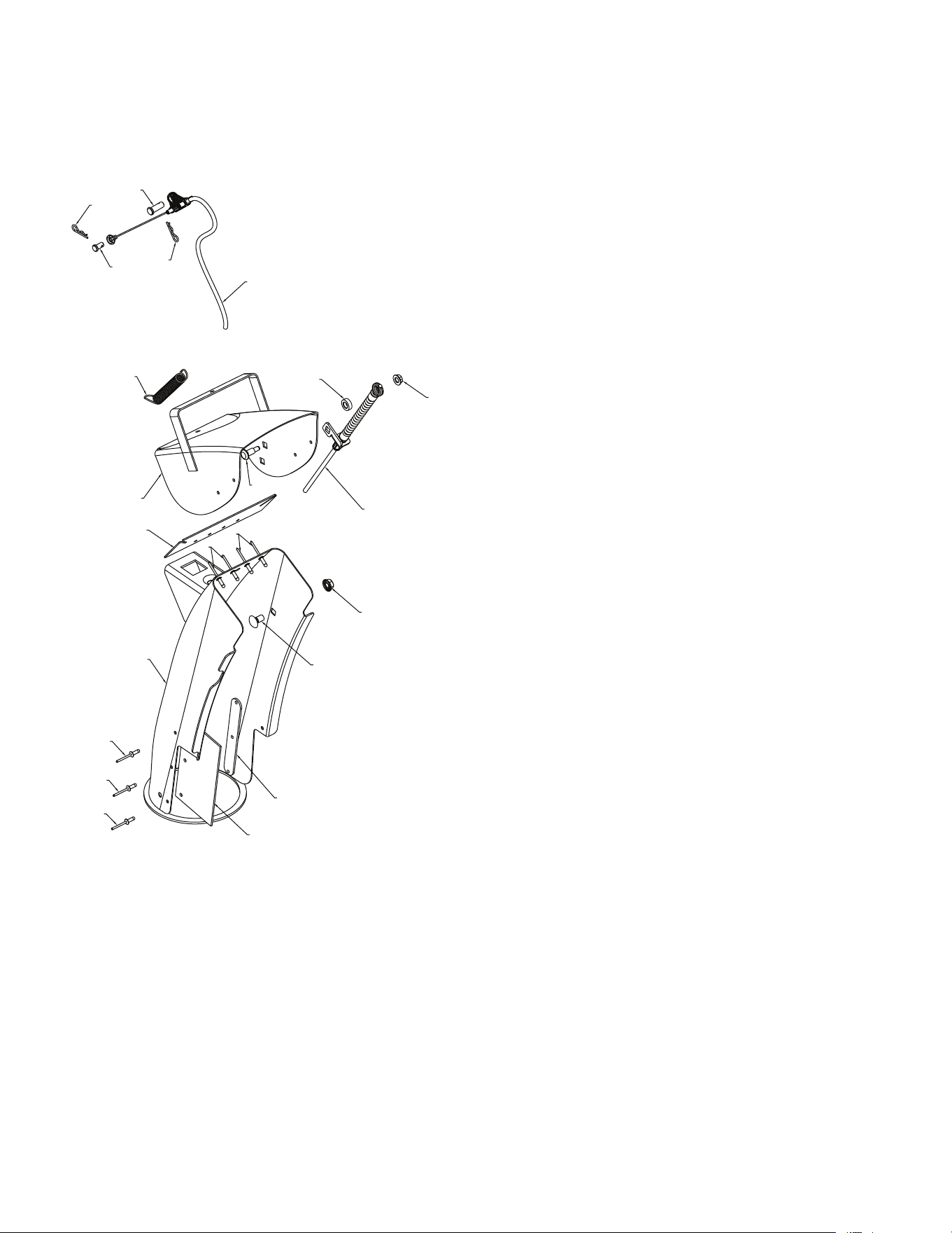
REPAIR PARTS SNOW THROWER - - MODEL NUMBER 944.103251
AUGER HOUSING / IMPELLER ASSEMBLY
NOTE: All component dimensions given in U.S. inches. 1 inch = 25.4 mm
IMPORTANT: Use only Original Equipment Manufacturer (O.E.M.) replacement parts.
Failure to do so could be hazardous, damage your snow thrower and void your warranty.
12
13
13
13
13
14
14
14
14
15
11
3
4
1
2
5
6
6
6
7
7
7
8
8
9
9
10
05.09.009-J

23
NOTE: All component dimensions given in U.S. inches. 1 inch = 25.4 mm
IMPORTANT: Use only Original Equipment Manufacturer (O.E.M.) replacement parts.
Failure to do so could be hazardous, damage your snow thrower and void your warranty.
KEY PART
NO. NO. DESCRIPTION
REPAIR PARTS SNOW THROWER - - MODEL NUMBER 944.103251
AUGER HOUSING / IMPELLER ASSEMBLY
1 501149601 GEARBOX AUGER
2 586607202 IMPELLER STEEL
3 587402401 PULLEY IMPELLER – SCREW ON
4 585056901 CHUTE DISCHARGE BASE
5 178675X008 BRACKET CORNER DISCHARGE BASE
6 588077501 BOLT SHEAR 1/4-20
7 73800400 NUT NYLOCK 1/4-20
8 585691301 NUT FLANGE NYLOCK 5/16-18 - BLK
9 585691201 BOLT CARRIAGE WAFER HEAD 5/16-18 X 5/8 BLK
10 581632002 BRACKET BELT KEEPER LOWER
11 581592502 BRACKET INTERFACE
12 198791 BEARING BALL
13 163183 SCREW HEX HEAD 5/16-18 X 5/8
14 427942 NUT FLANGE NYLOCK 5/16-18
15 587587202 LOWER AUGER BELT GUIDE
24
KEY PART
NO. NO. DESCRIPTION
KEY PART
NO. NO. DESCRIPTION
NOTE: All component dimensions given in U.S. inches. 1 inch = 25.4 mm
IMPORTANT: Use only Original Equipment Manufacturer (O.E.M.) replacement parts.
Failure to do so could be hazardous, damage your snow thrower and void your warranty.
REPAIR PARTS SNOW THROWER - - MODEL NUMBER 944.103251
AUGER HOUSING / IMPELLER ASSEMBLY
1
2
05.09.006-C
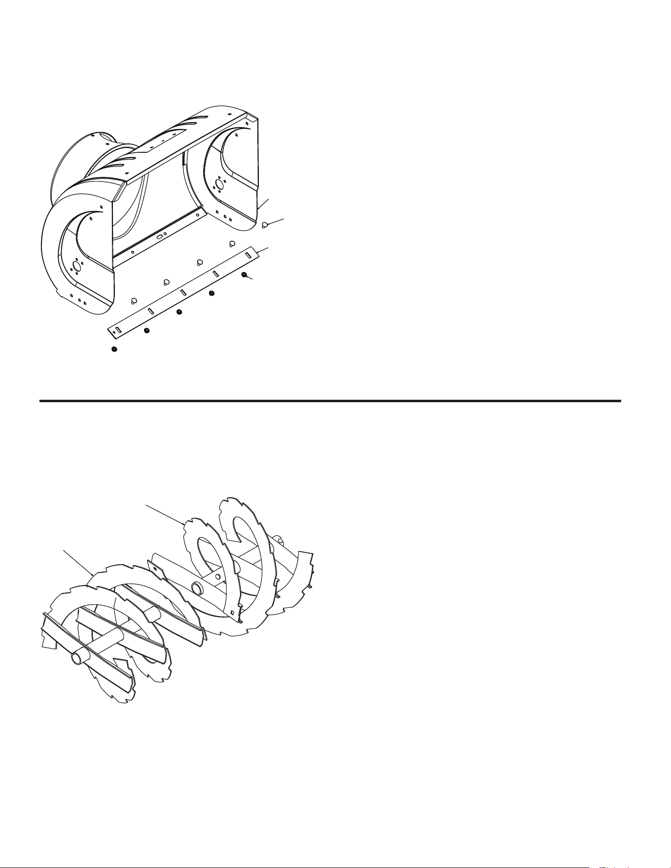
1 420495X 479 AUGER 27 LH
2 420496X479 AUGER 27 RH
05.09.011-C
1
2
3
4
5X
5X
1 581708373 AUGER HOUSING
2 404932X479 SCRA PER BAR
3 72270505 CARRIAGE BOLT 5/16-18 X
.625 GR5
4 155377 NUT 5/16-18

25
KEY PART
NO. NO. DESCRIPTION
KEY PART
NO. NO. DESCRIPTION
KEY PART
NO. NO. DESCRIPTION
NOTE: All component dimensions given in U.S. inches. 1 inch = 25.4 mm
IMPORTANT: Use only Original Equipment Manufacturer (O.E.M.) replacement parts.
Failure to do so could be hazardous, damage your snow thrower and void your warranty.
REPAIR PARTS SNOW THROWER - - MODEL NUMBER 944.103251
AUGER HOUSING / IMPELLER ASSEMBLY
05.09.007-A
2
2
3
3
1
1
3
3
1 420478 AUGER BEARING
2 411939 BEARING PLUG
3 584299401 SCREW HI-LO WASHD
5/16-14 X 1.00
05.09.039-A
1
2
3
1 192199 TOOL CLEANOUT
2 405400 CLIP CLEANOUT TOOL
3 194189 SCREW HEX WASHER
13-16 X 5/8
05.12.002-A
1
1
2
2
3
1 435951 PLATE SKID PLASTIC HDPE
2 585802801 NUT LARGE FLANGE 5/16-18
BLK
3 585802901 BOLT CARRIAGE 5/16-18 X
1.25 – BLK
26
NOTE: All component dimensions given in U.S. inches. 1 inch = 25.4 mm
IMPORTANT: Use only Original Equipment Manufacturer (O.E.M.) replacement parts.
Failure to do so could be hazardous, damage your snow thrower and void your warranty.
KEY PART
NO. NO. DESCRIPTION
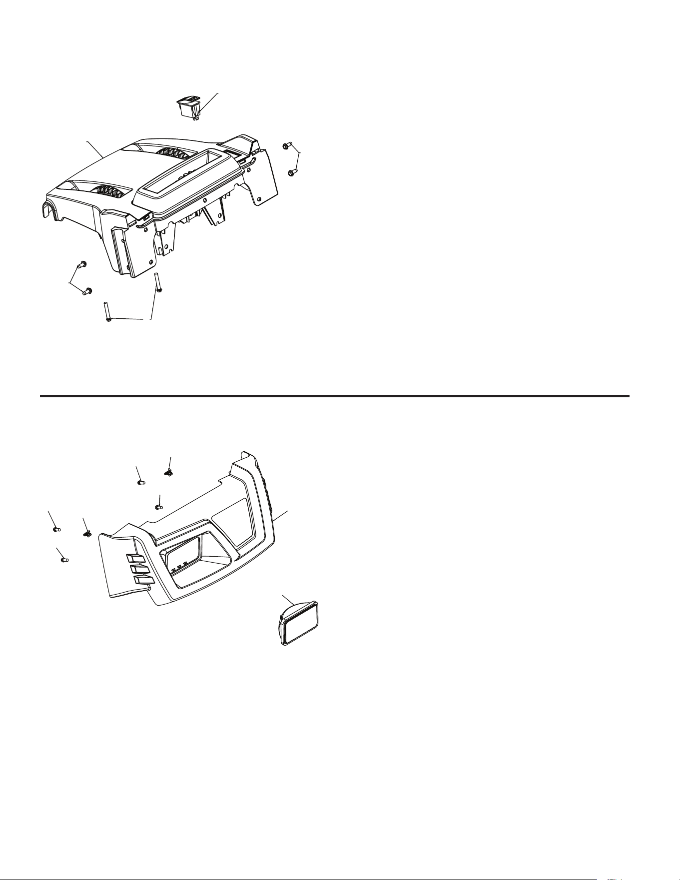
REPAIR PARTS SNOW THROWER - - MODEL NUMBER 944.103251
CONTROL PANEL / DISCHARGE CHUTE
KEY PART
NO. NO. DESCRIPTION
05.07.015-D
1
2
3
3
3
3
4
4
1 581128111 CONSOLE COVER
CRAFTSMAN
2 586181001 FLOOD LIGHT
3 194189 SCREW HI-LO 13-16 X 5/8
4 581928701 PANEL CLIP
- - 183784 BULB (NOT SHOWN)
05.07.009-A
1
2
3
3
4
1 581131203 CONSOLE BASE MULTICONT
W/SWITCH
2 585805001 SWITCH GRIP HEATED BLACK
3 17060410 SCREW TA SEMI GIMLE 1/4-
20 X .62
4 581329501 SCREW HEX WASHER 13-16
X 1.50
27
NOTE: All component dimensions given in U.S. inches. 1 inch = 25.4 mm
IMPORTANT: Use only Original Equipment Manufacturer (O.E.M.) replacement parts.
Failure to do so could be hazardous, damage your snow thrower and void your warranty.
KEY PART
NO. NO. DESCRIPTION
REPAIR PARTS SNOW THROWER - - MODEL NUMBER 944.103251
CONTROL PANEL / DISCHARGE CHUTE
KEY PART
NO. NO. DESCRIPTION
KEY PART
NO. NO. DESCRIPTION
1
1
2
3
3
3
4
4
4
5
5
5
6
7
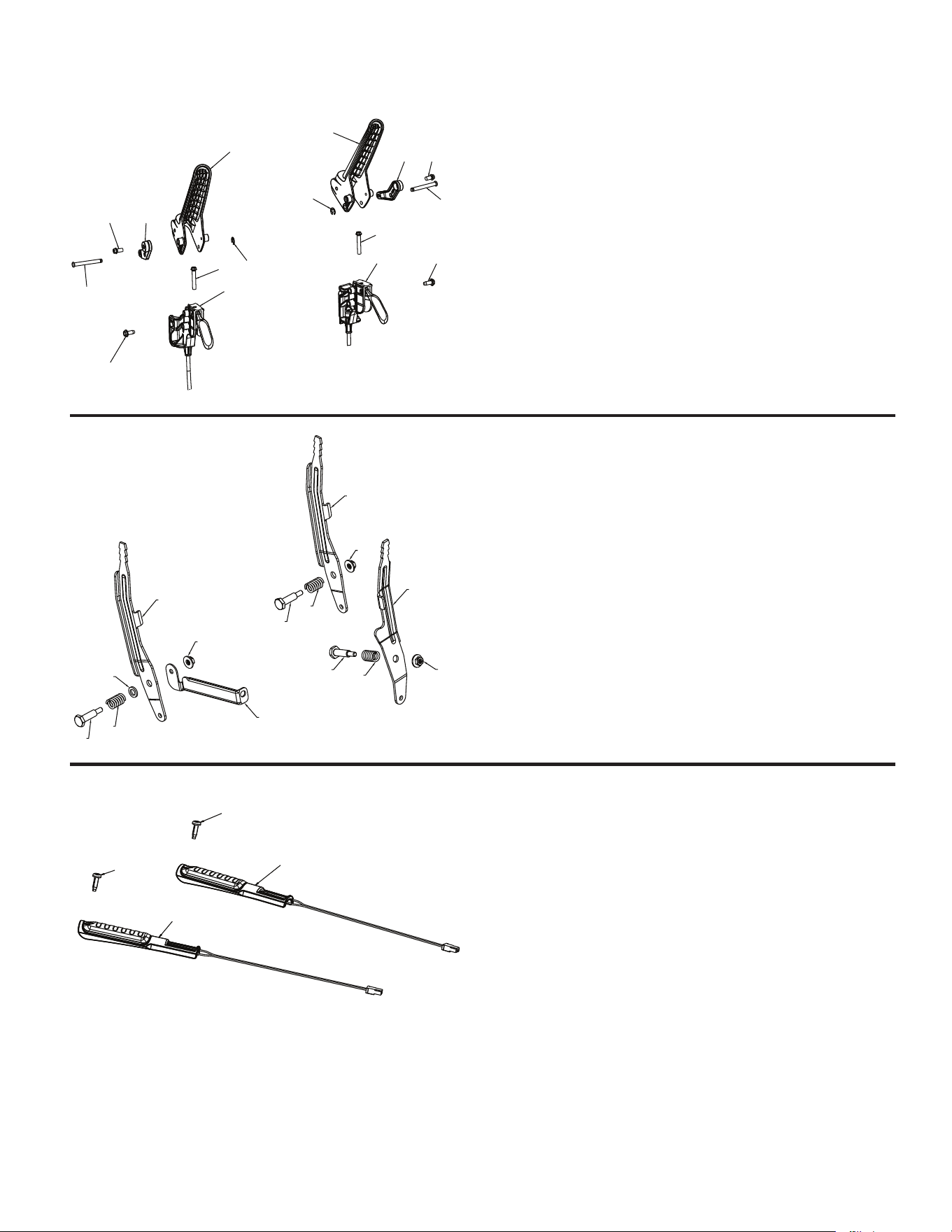
05.08.005-C
1 581123902 LEVER CONTROL SPEED/DEFL
2 581241602 LEVER CONTROL CHUTE ROT
3 581329701 BOLT SHOULDER 1/4-20
4 581329601 SPRING COMPRESSION
5 586668901 NUT FL LOCK 1/4-20
6 584468402 BRACE SUPPORT SPEED
7 587031301 WASHER .625 X .375 X .094
NYLON 6/6
3
3
4
1
2
5
6
6
7
7
8
8
9
9
10
10
05.08.013-A
1 588263901 CABLE, POWER STEER - LHS
2 588263902 CABLE, POWER STEER - RHS
3 587463001 LEVER, CONTROL
4 587739701 LEVER, CABLE ARM - LHS
5 587739702 LEVER, CABLE ARM - RHS
6 581329501 SCREW HI-LO 13-16 X 1.50
7 17060410 SCREW 1/4-20 X .625
8 17411308 SCREW HI-LW 13-16 X .500
9 588147701 PIN, GROOVED
10 12000014 E-RING
1
1
2
2
05.08.008-F
1 588775901 GRIP HANDLE HEATED
2 442250 SCREW PAN HD TORX
1/4-20 X .75
28
NOTE: All component dimensions given in U.S. inches. 1 inch = 25.4 mm
IMPORTANT: Use only Original Equipment Manufacturer (O.E.M.) replacement parts.
Failure to do so could be hazardous, damage your snow thrower and void your warranty.
KEY PART
NO. NO. DESCRIPTION
KEY PART
NO. NO. DESCRIPTION
REPAIR PARTS SNOW THROWER - - MODEL NUMBER 944.103251
CONTROL PANEL / DISCHARGE CHUTE
3
3
4
5
12
2
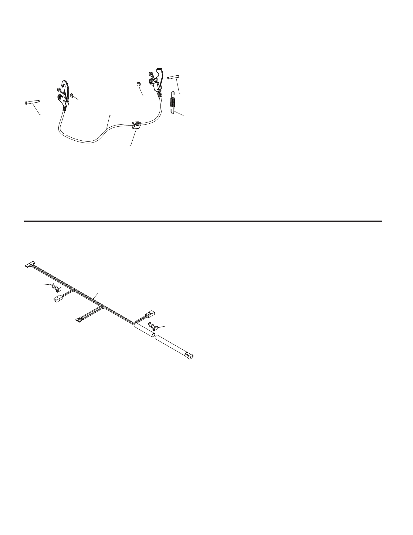
05.08.001-C
1 587332502 CABLE INTERLOCK
2 431762 PIN GROOVED
3 12000014 E-RING
4 581151201 SPRING RETURN
5 197991 CLIP CABLE BLACK
1
2
2
05.19.002-A
1 587535701 HARNESS WIRE LIGHTS &
GRIPS
2 145006 WIRE RETAINER
29
NOTE: All component dimensions given in U.S. inches. 1 inch = 25.4 mm
IMPORTANT: Use only Original Equipment Manufacturer (O.E.M.) replacement parts.
Failure to do so could be hazardous, damage your snow thrower and void your warranty.
KEY PART
NO. NO. DESCRIPTION
REPAIR PARTS SNOW THROWER - - MODEL NUMBER 944.103251
CONTROL PANEL / DISCHARGE CHUTE
3
4
4
1
2
5
6
7
8
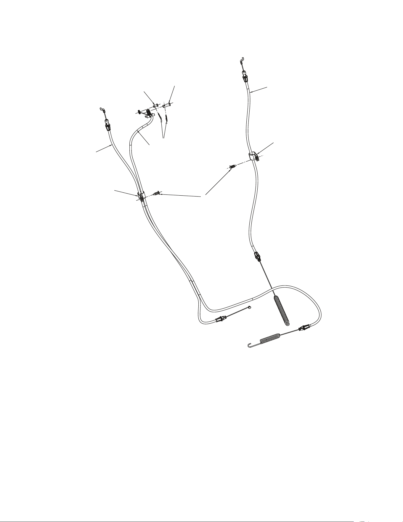
05.08.011-C
1 582519001 CABLE CONTROL DRIVE
2 588113801 CABLE CONTROL AUGER
3 588122301 CABLE CONTROL SPEED
4 197991 CLIP CABLE
5 428124 FASTENER PUSH .250
6 581329401 PIN CLEVIS 5/16
7 423303 HAIRPIN
8 585808301 PIN CLEVIS 1/4
30
NOTE: All component dimensions given in U.S. inches. 1 inch = 25.4 mm
IMPORTANT: Use only Original Equipment Manufacturer (O.E.M.) replacement parts.
Failure to do so could be hazardous, damage your snow thrower and void your warranty.
KEY PART
NO. NO. DESCRIPTION
REPAIR PARTS SNOW THROWER - - MODEL NUMBER 944.103251
CONTROL PANEL / DISCHARGE CHUTE
1
2
3
4
4
4
5
5
5
6
7
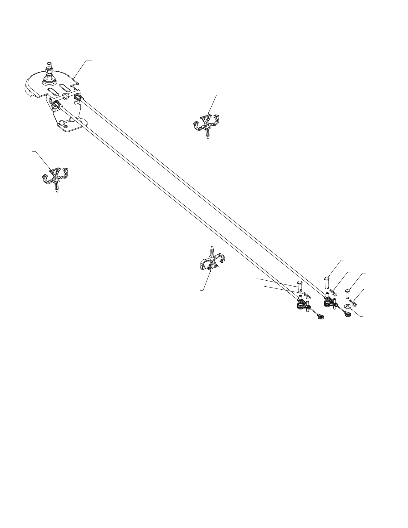
05.08.010-A
1 587803401 CABLE CHUTE ROTATOR ASM
2 581329401 PIN CLEVIS 5/6 X 7/8
3 77100812 PIN CLEVIS 1/4 X 3/4
4 423303 HAIRPIN SOFT ZINC
5 584652201 CLIP CONDUIT DOUBLE
6 586682101 WASHER
7 587130801 PIN CLEVIS 5/16 X 1
31
NOTE: All component dimensions given in U.S. inches. 1 inch = 25.4 mm
IMPORTANT: Use only Original Equipment Manufacturer (O.E.M.) replacement parts.
Failure to do so could be hazardous, damage your snow thrower and void your warranty.
KEY PART
NO. NO. DESCRIPTION
REPAIR PARTS SNOW THROWER - - MODEL NUMBER 944.103251
CONTROL PANEL / DISCHARGE CHUTE
*12
*13
*14
*15
*16
*11
3
4
4
4
4
4
1
2
5
6
7
7
8
9
10
10
05.11.006-E
1 588077803 CHUTE WELDMENT
(INCLUDES 1-6)
2 - - - - - - - - - - DEFLECTOR WELDMENT
3 - - - - - - - - - - DEFLECTOR SEAL
4 - - - - - - - - - - POP RIVET
5 - - - - - - - - - - CHUTE SNOW SHIELD
6 - - - - - - - - - - SHIELD STRAP RETAINER
7 586961501 CABLE ASM DEFLECTOR -
BOWDEN
8 581329401 PIN CLEVIS 5/16 X .875
9 585808301 PIN CLEVIS 1/4 X .312
10 423303 HAIRPIN RETAINER
*11 184505 DEFLECTOR SPRING
*12 501417301 CARRIAGE BOLT 1/4-20 X .544
*13 585691401 NUT 1/4-20
*14 585832001 CARRIAGE BOLT 3/8-16 X .625
*15 73970500 NUT 5/16-18
*16 501417401 WASHER .362 X .625 X .205
NYLON
NOTE: ALL ITEMS MARKED WITH AN * ARE
PROVIDED IN THE BAG OF ITEMS SHIPPED LOOSE
WITH PRODUCT.
32
NOTE: All component dimensions given in U.S. inches. 1 inch = 25.4 mm
IMPORTANT: Use only Original Equipment Manufacturer (O.E.M.) replacement parts.
Failure to do so could be hazardous, damage your snow thrower and void your warranty.
KEY PART
NO. NO. DESCRIPTION
KEY PART
NO. NO. DESCRIPTION
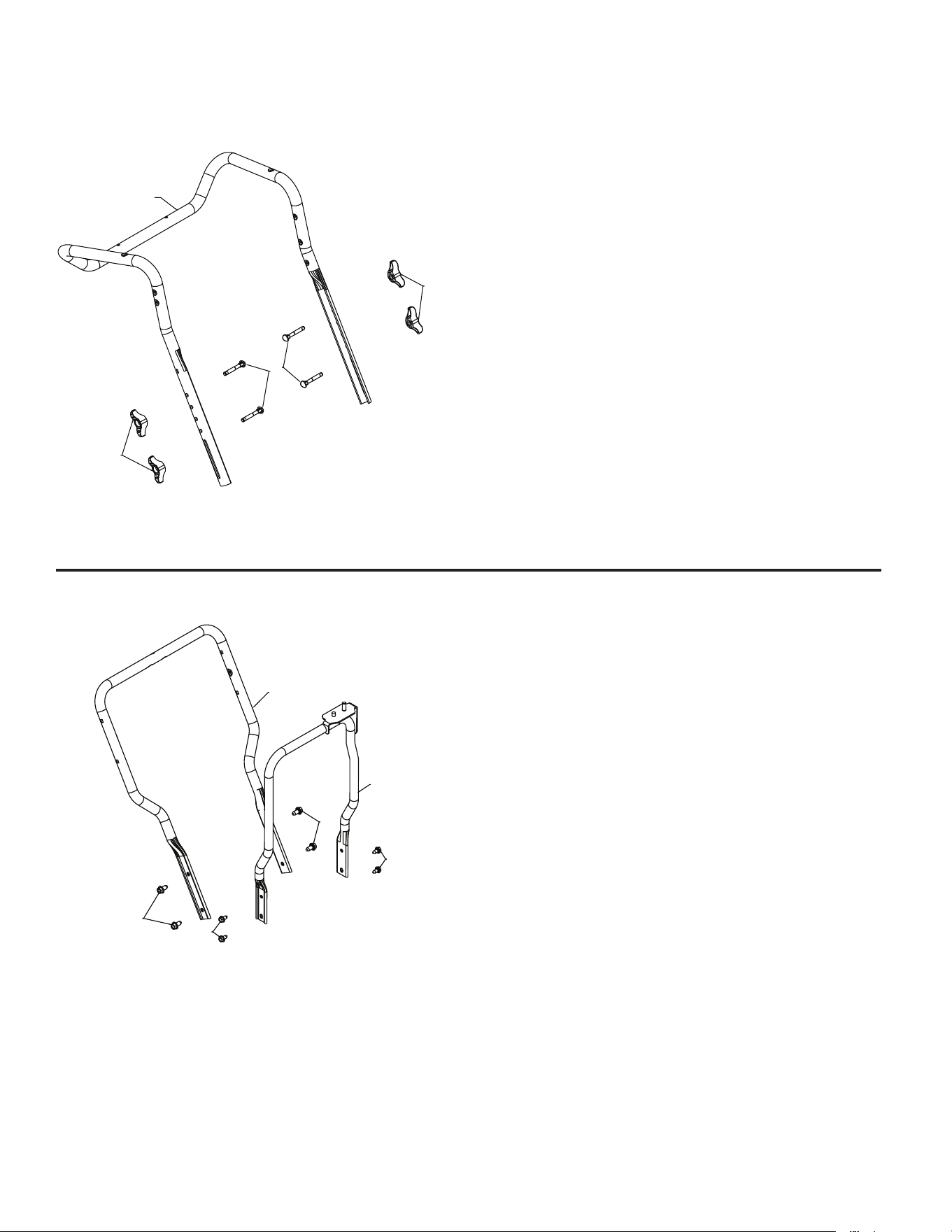
REPAIR PARTS SNOW THROWER - - MODEL NUMBER 944.103251
HANDLES
1 588672102 LOWER HANDLE
2 17000612 SCREW HEX WASH HD
3/8-16 X .75
3 581622002 CHUTE ROTATOR SUPPORT
ASM
4 17000510 BOLT HEX 5/16-18
1
2
2
3
4
4
05.05.001-E
3
1
2
2
05.06.001-G
1 588160802 UPPER HANDLE
2 189713X428 HANDLE KNOB STD BLACK
3 588059901 SCREW 5/16-18 X 2.25
CONCAVE HEAD WITH PATCH
33
KEY PART
NO. NO. DESCRIPTION
NOTE: All component dimensions given in U.S. inches. 1 inch = 25.4 mm
IMPORTANT: Use only Original Equipment Manufacturer (O.E.M.) replacement parts.
Failure to do so could be hazardous, damage your snow thrower and void your warranty.
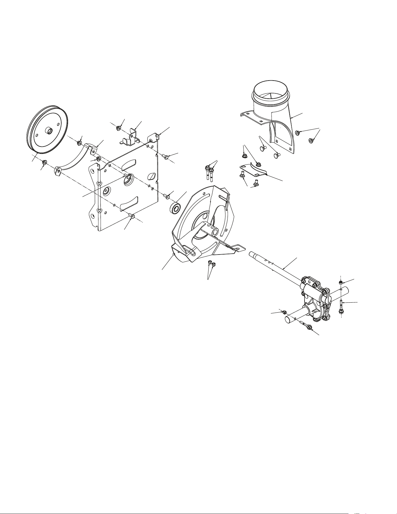
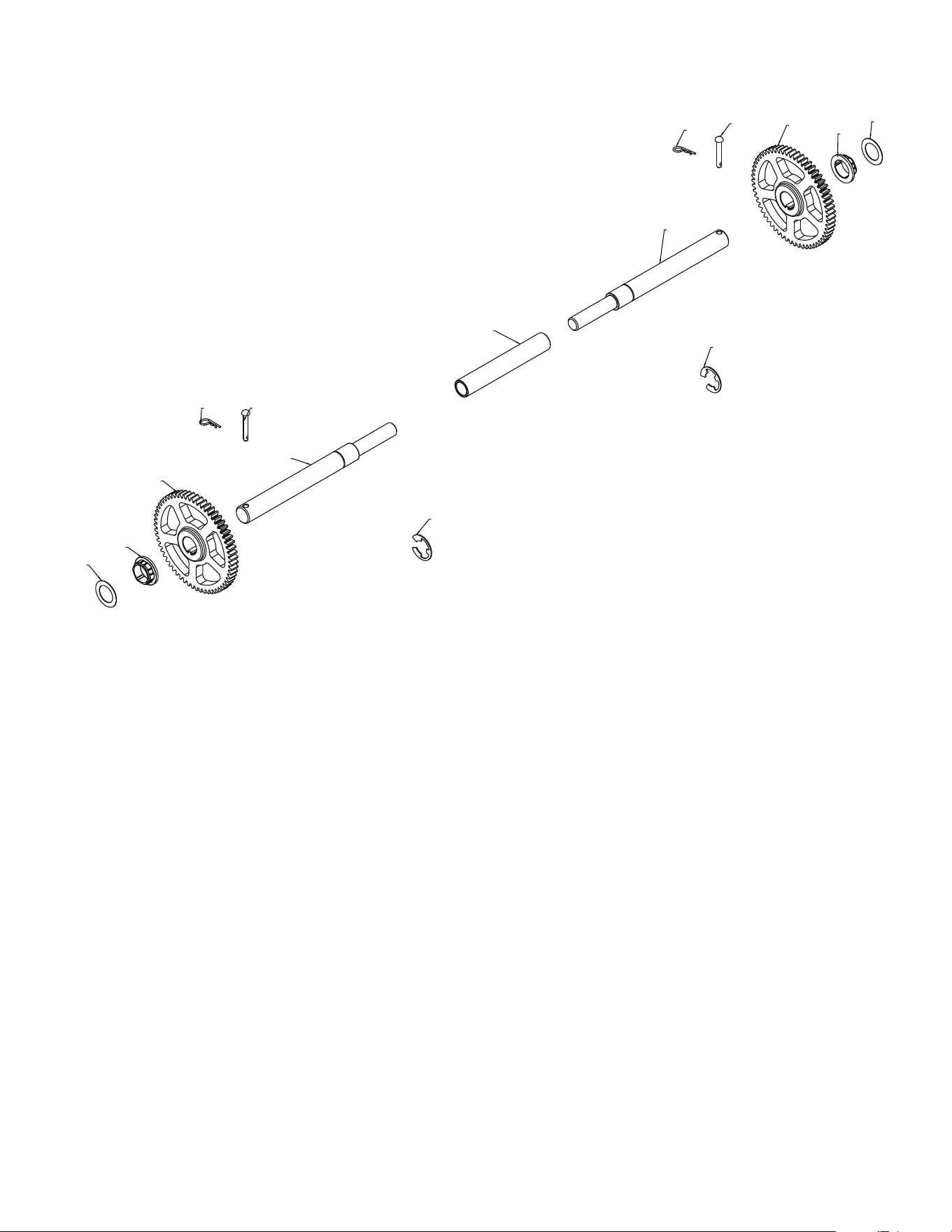
REPAIR PARTS SNOW THROWER - - MODEL NUMBER 944.103251
DRIVE
1
1
2
2
3
3
4
4
5
5
6
6
7
7
8
05.03.002-B
1 444949 WASHER 1.00
2 587978901 BUSHING HEX 1 SHAFT
3 588518601 GEAR 59T DRIVEN
4 12000053 RETAINING RING
5 580752601 AXLE SHAFT SPLIT
6 4497H RETAINER SPRING 1 ZINC
7 126875X RIVET RD HD DRILLED 1/4 DIA
8 580752501 AXLE SLEEVE
34
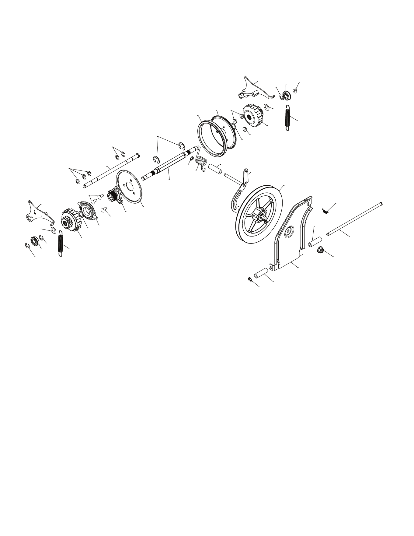
REPAIR PARTS SNOW THROWER - - MODEL NUMBER 944.103251
DRIVE
NOTE: All component dimensions given in U.S. inches. 1 inch = 25.4 mm
IMPORTANT: Use only Original Equipment Manufacturer (O.E.M.) replacement parts.
Failure to do so could be hazardous, damage your snow thrower and void your warranty.
12
13
14
15
16
17
18
19
20
20
21
21
11
3
4
4
4
1
2
5
6
6
7
8
9
10
12
13
13
14
16
17
10
22
23
23
24
25
26
27
27
28
05.02.002-G

35
NOTE: All component dimensions given in U.S. inches. 1 inch = 25.4 mm
IMPORTANT: Use only Original Equipment Manufacturer (O.E.M.) replacement parts.
Failure to do so could be hazardous, damage your snow thrower and void your warranty.
KEY PART
NO. NO. DESCRIPTION
REPAIR PARTS SNOW THROWER - - MODEL NUMBER 944.103251
DRIVE
1 521991101 NUT HEX FLANGE LK 1/2-13
2 587703402 SWING PLATE FRICTION PULL
3 581123001 ROD TIP PLATE
4 581732701 SPACER DRIVE
5 193885 LATCH SPRING
6 12000007 E-RING RETAINER
7 581328401 FRICTION DISC COMBO PULLEY
8 587193403 BRACKET YOKE ASSEMBLY
9 581315301 SPRING TORSION DRIVE
10 585263801 EXTENSION SPRING
11 585691501 NUT HEX FLANGE LOCK 5/16-18
12 580756201 BEARING 9/16 I.D. 1622-2RSNR
13 580756102 RETAINING RING 1622-2RSNR
14 580751301 WASHER FLAT .59 I.D. X 1.065 X 25 GA
15 580756601 PAWL ASM RH
16 580756001 GEAR ASM PLANETARY
17 580756301 WASHER FLAT .6875 I.D. X 1.00 X 21 GA
18 175344 TRUNNION BEARING ASM
19 581090901 HUB RUBBER WHEEL
20 72110506 BOLT CARRIAGE 5/16-18 X .75
21 581091002 PLATE RUBBER WHEEL
22 581091101 RING RUBBER WHEEL
23 586644301 E-RING
24 580755101 ROD PAWL
25 12000022 E-RING
26 580752401 SHAFT REDUCTION PWR STR
27 751153 NUT HEX FLANGE LK 5/16-18
28 580756701 PAWL ASM LH
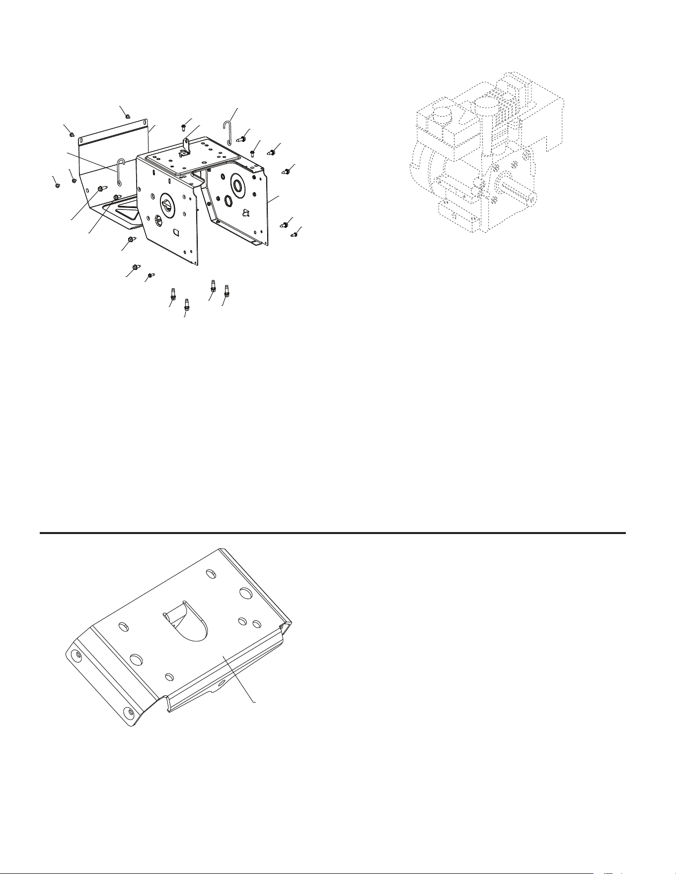
36
NOTE: All component dimensions given in U.S. inches. 1 inch = 25.4 mm
IMPORTANT: Use only Original Equipment Manufacturer (O.E.M.) replacement parts.
Failure to do so could be hazardous, damage your snow thrower and void your warranty.
KEY PART
NO. NO. DESCRIPTION
REPAIR PARTS SNOW THROWER - - MODEL NUMBER 944.103251
CHASSIS / ENGINE / PULLEYS
KEY PART
NO. NO. DESCRIPTION
- - - - - - - - - - B&S ENGINE 15C107-0040-F8
1
05.01.002-A
1 583940502 SMALL MOUNTING PLATE
3
4
1
2
2
2
2
5
5
5
5
6
6
7
7
7
7
7
7
8
8
9
9
9
9
05.01.001-G
1 580839403 FRAME
2 150406 ENGINE BOLT 3/8-16 X 1.280
DOGPOINT
3 580839503 FRAME COVER
4 501060403 SHIFTER BRACKET
5 17060410 SCREW HEX WASHER 1/4-20
X .625
6 588954501 WIREFORM SUPPORT CABLE
7 428867 BOLT HEXHD WASHER 5/16-
18 X .750
8 585217501 BOLT HEXHD WASHER 5/16-
18 X 1.000
9 17060408 SCREW HEX WASHER 1/4-20
X .500
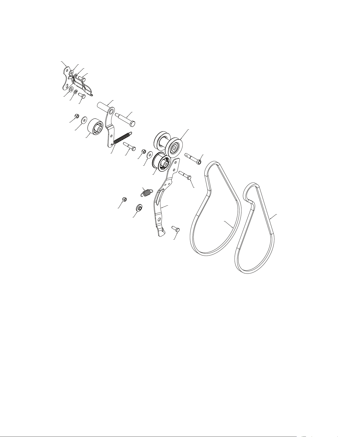
37
NOTE: All component dimensions given in U.S. inches. 1 inch = 25.4 mm
IMPORTANT: Use only Original Equipment Manufacturer (O.E.M.) replacement parts.
Failure to do so could be hazardous, damage your snow thrower and void your warranty.
KEY PART
NO. NO. DESCRIPTION
KEY PART
NO. NO. DESCRIPTION
REPAIR PARTS SNOW THROWER - - MODEL NUMBER 944.103251
CHASSIS / ENGINE / PULLEYS
12
13
14
15
16
17
18
19
20
11
3
3
4
4
1
2
2
5
6
6
6
7
7
8
9
10
10
05.04.001-K
1 588492802 BELT KEEPER BRACKET
2 19111216 WASHER 11/32 X 3/4 X 16 GA
3 10040500 LOCKWASHER 5/16 SPLIT HVY
4 74610512 CAPSCREW HEXHD 5/16-24 X
.75 GR 5
5 581338203 IDLER ARM DRIVE WELDMENT
6 73800500 NUT NYLOCK 5/16-18
7 59289 WASHER FLAT .328 X 1.00 X
.097
8 581141401 IDLER PULLEY 2.0 W/SPACER
9 580753001 RETURN SPRING IDLER ARM
DRIVE
10 74760528 BOLT HEXHD 5/16-18 X 1.75
11 581413801 SHOULDER BOLT 5/16-24 X
2.15
12 587893703 PULLEY ASM ENGINE
13 582 388401 BOLT HEXHD 3/8-24 X 2.375
14 580831106 ARM IDLER
15 587031201 RETURN SPRING IDLER ARM
16 587343701 BUSHING IDLER PIVOT
17 74760514 BOLT HEXHD 5/16-18 X .875
18 584216102 DRIVE BELT 4L X 38.2
19 501818201 IMPELLER BELT
20 586880201 IDLER PULLEY 2.0 FLANGE
LESS W/SPACER
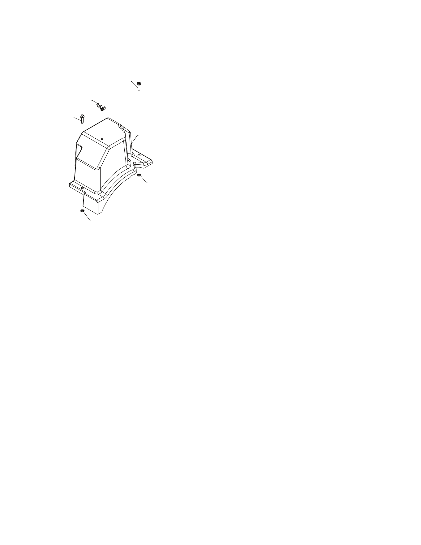
38
NOTE: All component dimensions given in U.S. inches. 1 inch = 25.4 mm
IMPORTANT: Use only Original Equipment Manufacturer (O.E.M.) replacement parts.
Failure to do so could be hazardous, damage your snow thrower and void your warranty.
KEY PART
NO. NO. DESCRIPTION
REPAIR PARTS SNOW THROWER - - MODEL NUMBER 944.103251
CHASSIS / ENGINE / PULLEYS
1
2
2
3
4
4
05.04.002-B
1 587105401 BELT COVER BLACK
ASSEMBLY (INCLUDES 2 & 4)
2 - - - - - - - - - BOLT HEX WSH THDRL 1/4-20
X 1
3 145006 CABLE GUIDE
4 - - - - - - - - - PALNUT 1/4 IN
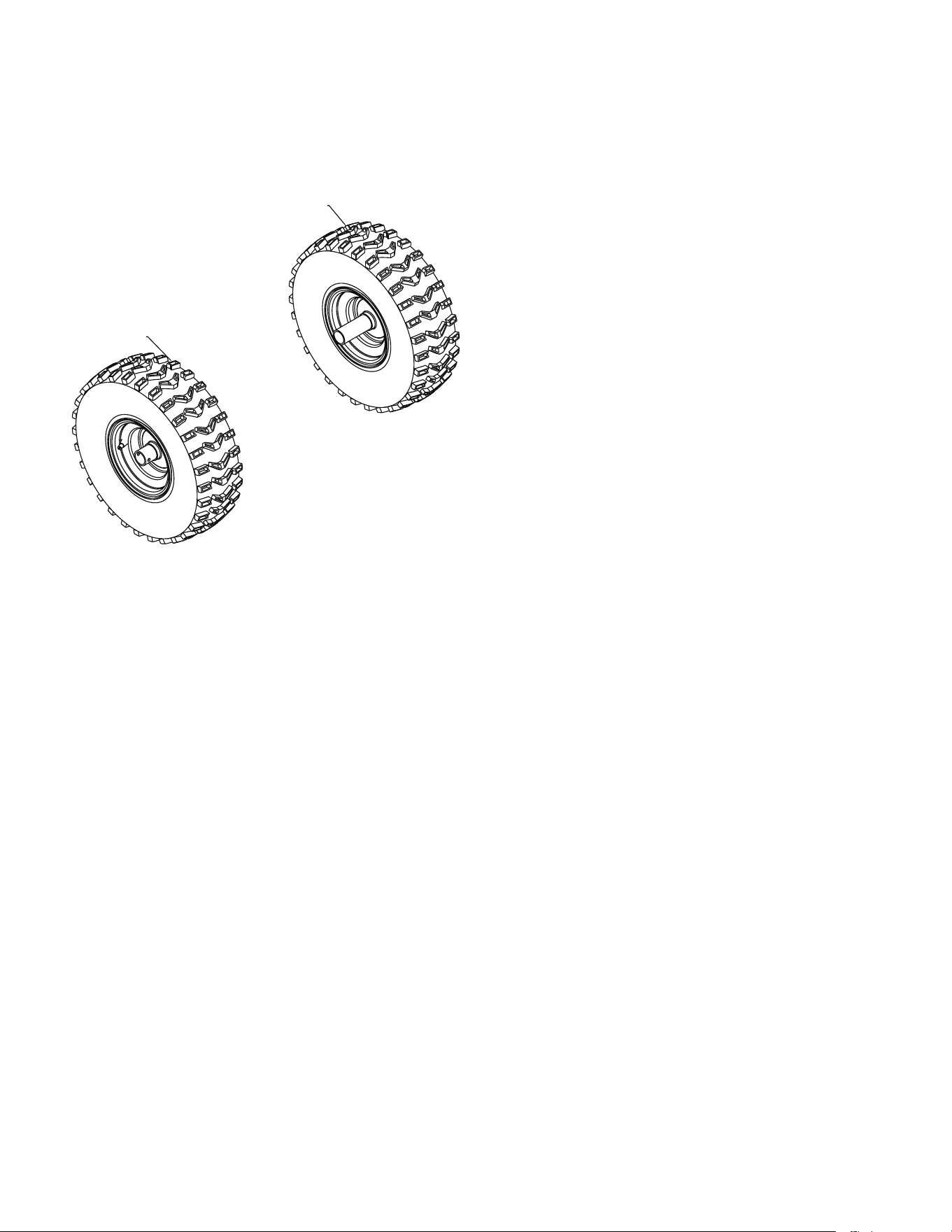
39
NOTE: All component dimensions given in U.S. inches. 1 inch = 25.4 mm
IMPORTANT: Use only Original Equipment Manufacturer (O.E.M.) replacement parts.
Failure to do so could be hazardous, damage your snow thrower and void your warranty.
KEY PART
NO. NO. DESCRIPTION
REPAIR PARTS SNOW THROWER - - MODEL NUMBER 944.103251
WHEELS
1
2
05.15.003-C
1 586710403 WHEEL 15 X 5.00 NPS LH 1.00
2 586710303 WHEEL 15 X 5.00 NPS RH 1.00
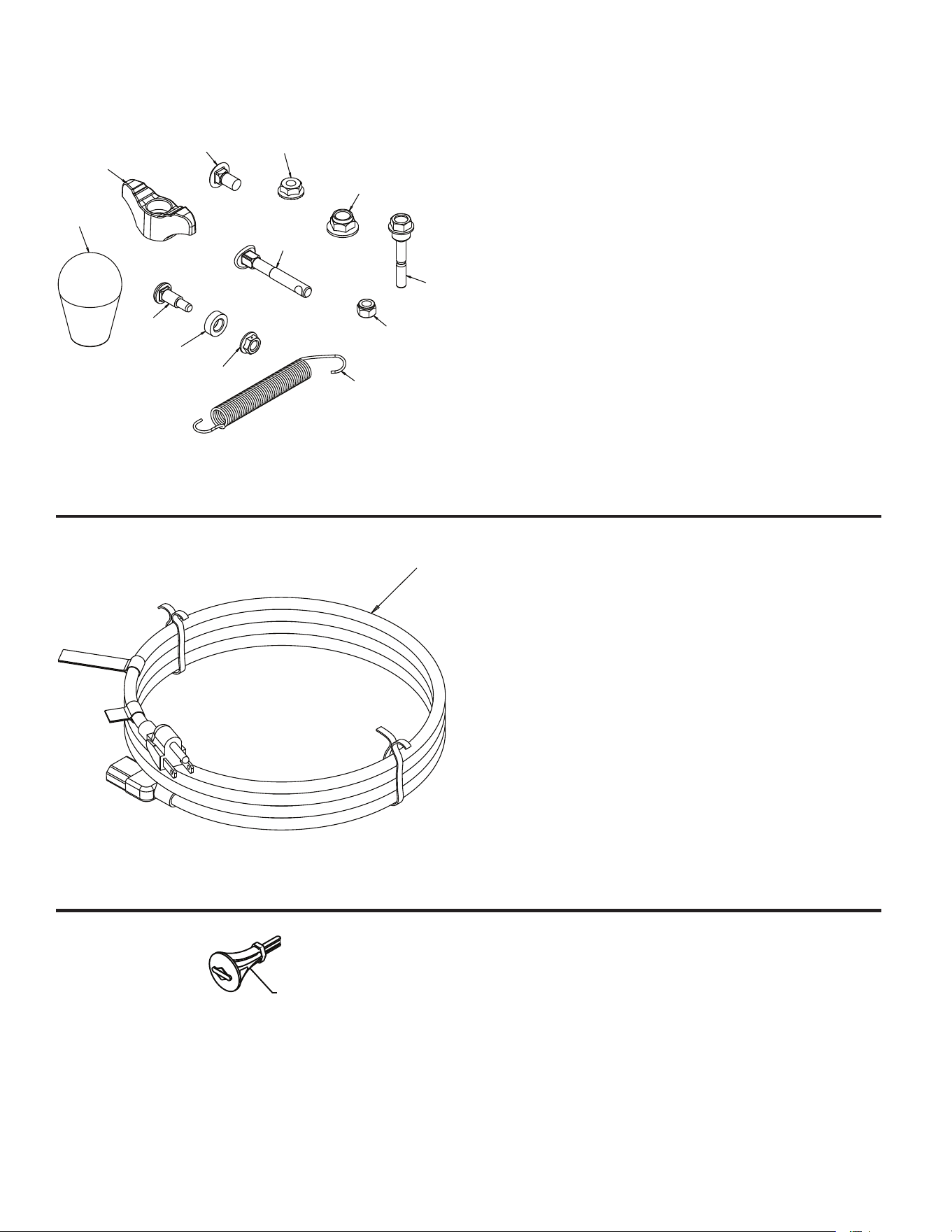
40
KEY PART
NO. NO. DESCRIPTION
KEY PART
NO. NO. DESCRIPTION
KEY PART
NO. NO. DESCRIPTION
REPAIR PARTS SNOW THROWER - - MODEL NUMBER 944.103251
BAG OF PARTS
NOTE: All component dimensions given in U.S. inches. 1 inch = 25.4 mm
IMPORTANT: Use only Original Equipment Manufacturer (O.E.M.) replacement parts.
Failure to do so could be hazardous, damage your snow thrower and void your warranty.
1
01.14.007-A
1 193071 SAFETY IGNITION KEY
1
05.19.003-A
1 198563 CORD ELECTRIC 6219 10FT
125V 3WIRE
12
11
3
4
1
2
5
6
7
89
10
05.18.008-B
1 588077501 BOLT 1/4-20 X 1.81
2 73800400 NUT NYLOCK 1/4-20
3 501417301 BOLT SHOULDER
4 585691401 NUT HEX FL 1/4-20 CTR
5 588252901 NUT NYLOCK 3/8-16
6 588059901 BOLT 5/16-18 X 2.25 CONCAVE
7 189713X428 KNOB 5/16-18 X .625
8 585832001 BOLT 5/16-18 X .625
9 73970500 NUT SERR FL LOCK 5/16-18
10 184505 SPRING DEFLECT CHUTE
11 581697501 KNOB SOFT TOUCH SLOTTED
12 501417401 WASHER NYLON
NI 588077606 KIT REPLACEMETN BAG OF
PARTS
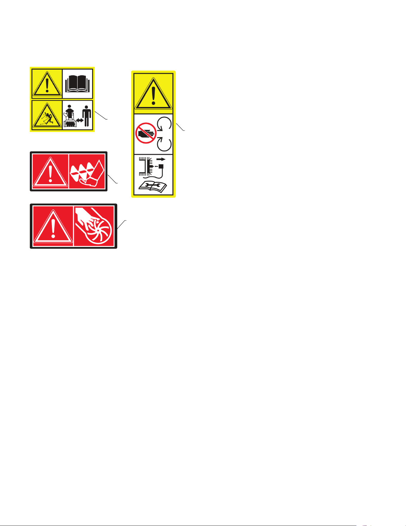
41
NOTE: All component dimensions given in U.S. inches. 1 inch = 25.4 mm
IMPORTANT: Use only Original Equipment Manufacturer (O.E.M.) replacement parts.
Failure to do so could be hazardous, damage your snow thrower and void your warranty.
KEY PART
NO. NO. DESCRIPTION
REPAIR PARTS SNOW THROWER - - MODEL NUMBER 944.103251
DECALS
1
2
3
4
05.16.001-A
1 184045 DECAL AUGER
2 199682 DECAL CHUTE
3 199683 DECAL AUGER SAFETY
4 184028 DECAL BELT GUIDE
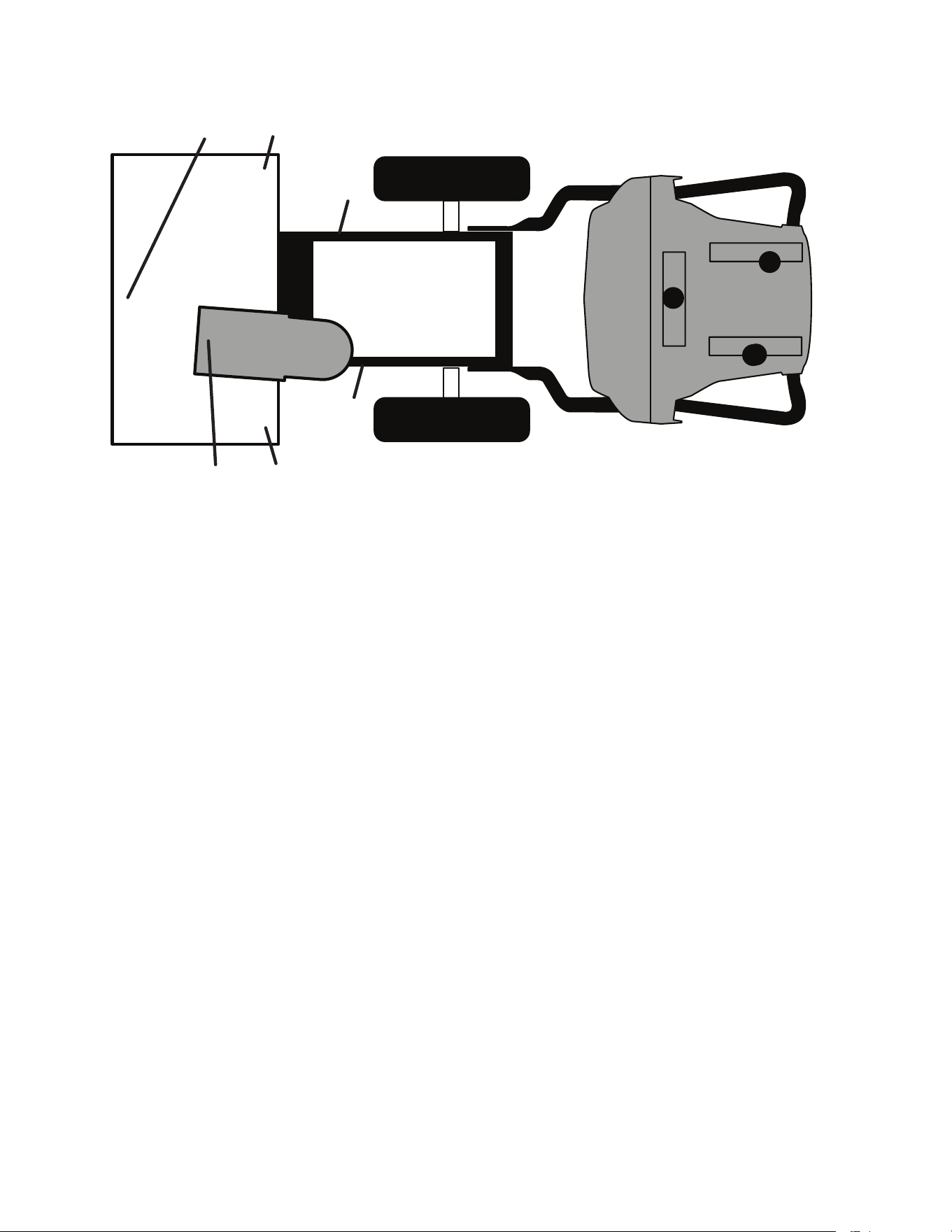
42
NOTE: All component dimensions given in U.S. inches. 1 inch = 25.4 mm
IMPORTANT: Use only Original Equipment Manufacturer (O.E.M.) replacement parts.
Failure to do so could be hazardous, damage your snow thrower and void your warranty.
REPAIR PARTS SNOW THROWER - - MODEL NUMBER 944.103251
DECALS
1
5
5
4
3
1
KEY PART
NO. NO. DESCRIPTION
1 199683 DECAL, DANGER
3 199682 DECAL, DANGER, DEFLECTOR
4 184045 DECAL, DANGER
5 184028 DECAL, BELT GUARD
- - 589430501 OWNER’S MANUAL, ENGLISH
- - 589430502 OWNER’S MANUAL, FRENCH
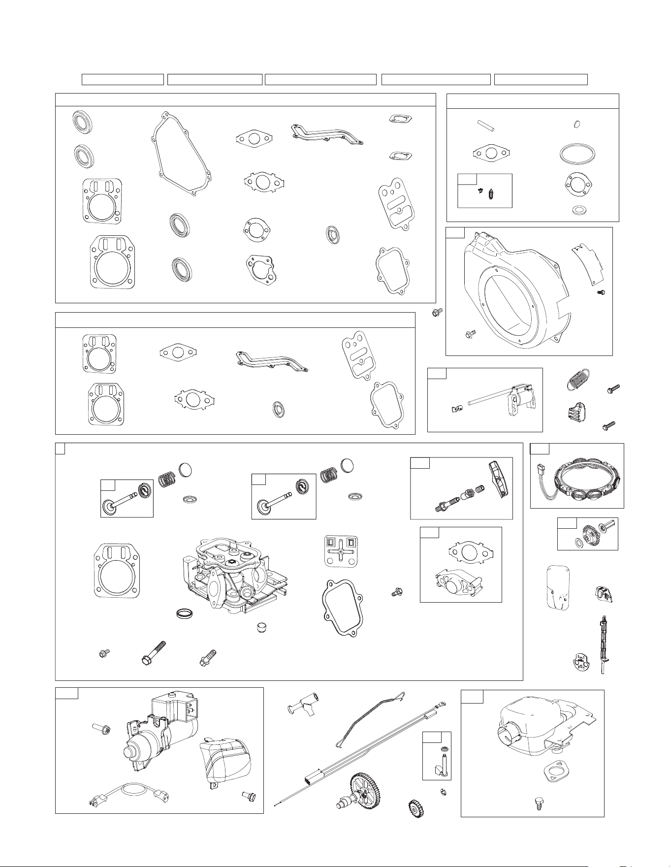
43
REPAIR PARTS SNOW THROWER - - MODEL NUMBER 944.103251
ENGINE, B&S MODEL NUMBER 15C107-0040-F8
104
137
276
121
127
163
105
51
12
20
7
993
1022
883
3
868
358
883A
3A
7A
20A
51A
163
163A
585
51
7
993
1022
868
1095
7A
51A
585
51
48 1330132910581036
334
632
1119
474
635
209A
485
851
333
309
732
727
697
735
578
65
304
305
37
78
36
238
40
35
238
40
1022
830
1029
13
34
192
33
5
1034
869
7A
868
553
553
914A
122
51A
365
305
613
883
300
46
746
742
220
219
615
616
472
108
109
610
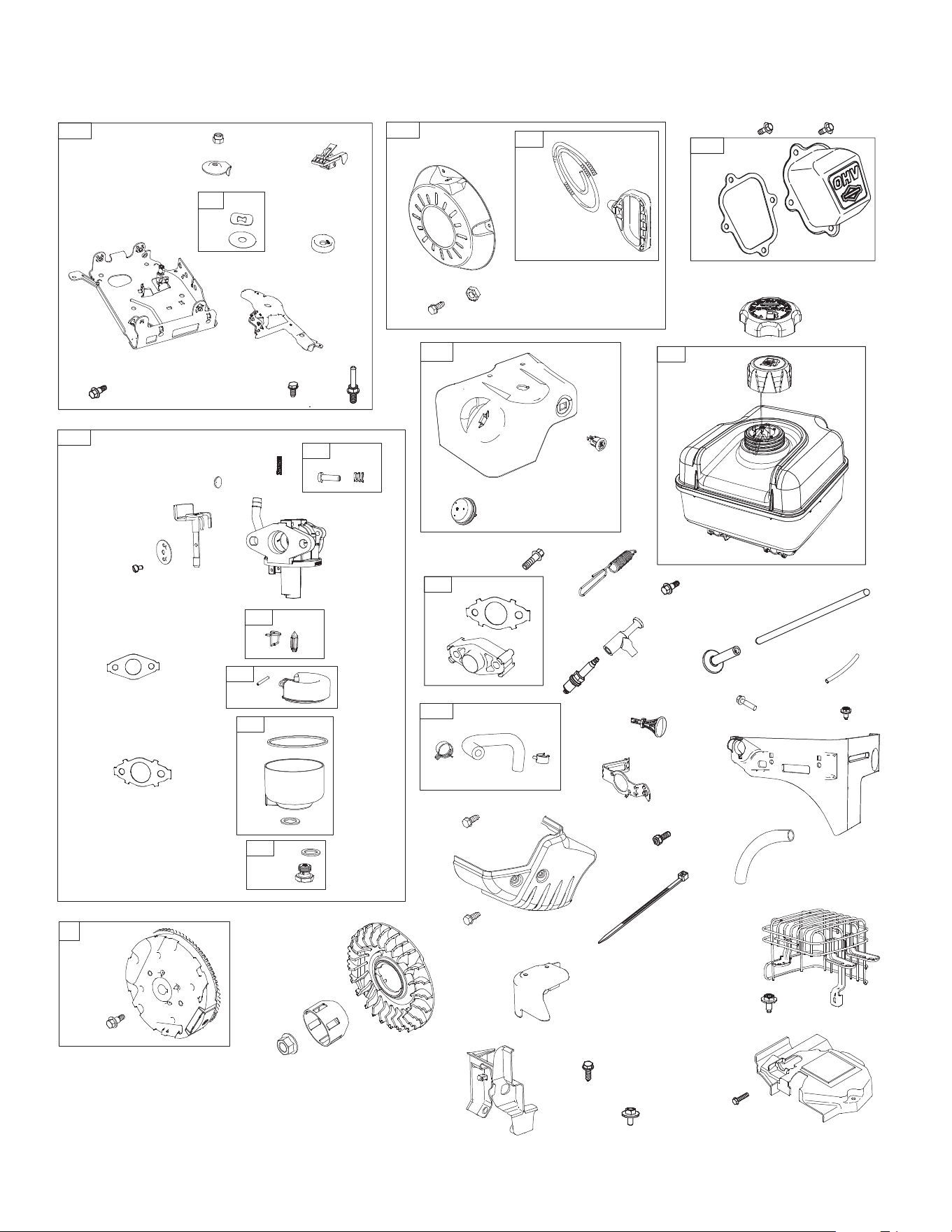
44
REPAIR PARTS SNOW THROWER - - MODEL NUMBER 944.103251
ENGINE, B&S MODEL NUMBER 15C107-0040-F8
1026
45
914
914A
1022
1023
337
635
209
65A
608
592
458
188
222
190
1230
1147
773
504
668
621
271
493
318
528
11
1251A
604
564
1252
1252A
1251
23
1070
455
332
1005
990
892
976
731A
1054
832
836
663
281
663A
1196
731
1196A
190
972
957A
957
365
122
51A
51
95
692
104
137
276
130
276
117
975
133
127
125
98
97
105
51A
601
187
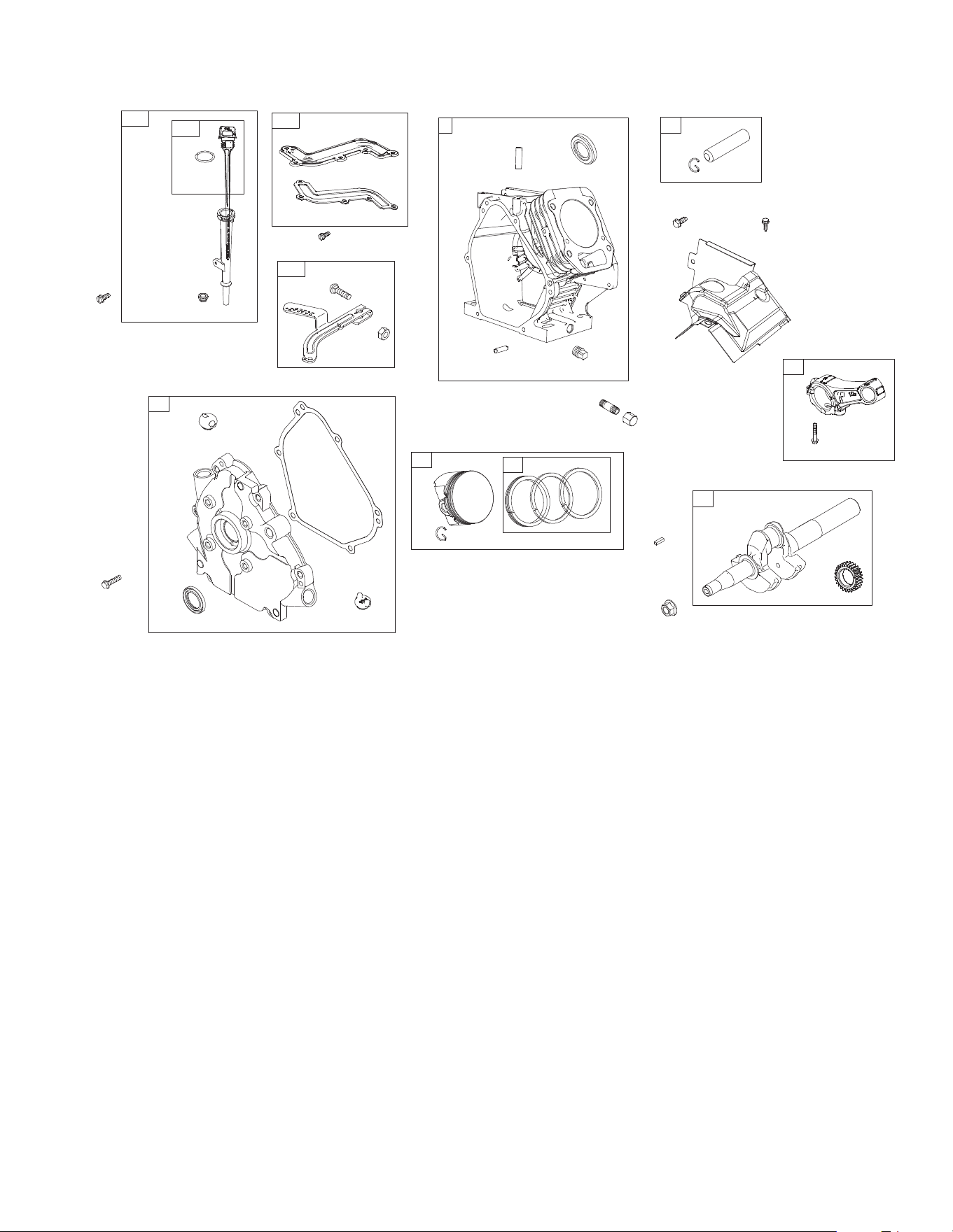
45
REPAIR PARTS SNOW THROWER - - MODEL NUMBER 944.103251
ENGINE, B&S MODEL NUMBER 15C107-0040-F8
KEY PART
NO. NO. DESCRIPTION
KEY PART
NO. NO. DESCRIPTION
32
29
842
287
523
847
524
27
28
27
25
26
505
562
227
24
741
16
332
584
585
684
552
718
15
3
307
1
306
307A
1427
998
22
12
20
18
21
415
1 794188 CYLINDER ASSEMBLY
3 299819S SEAL-OIL (MAGNETO SIDE)
5 594701 HEAD-CYLINDER
7 698210 GASKET-CYLINDER HEAD
7A 791716 GASKET-CYLINDER HEAD
11 695745 TUBE-BREATHER
12 699485 GASKET-CRANKCASE
13 594518 SCREW (CYLINDER HEAD)
15 691686 PLUG-OIL DRAIN
16 594808 CRANKSHAFT
18 699696 COVER-CRANKCASE
20 692550 SEAL-OIL (PTO SIDE)
21 291658S CAP-OIL FILL
22 594519 SCREW (CRANKCASE COV-
ER/SUMP)
23 798882 FLYWHEEL
24 796335 KEY-FLYWHEEL (STEEL)
25 791786 PISTON ASSEMBLY (STAN-
DARD)
791791 PISTON ASSEMBLY (.020”
OVERSIZE)
26 791787 RING SET (STANDARD)
791792 RING SET (.020” OVERSIZE)
27 690975 LOCK-PISTON PIN
28 690229 PIN-PISTON
29 791783 ROD-CONNECTING
32 791784 SCREW (CONNECTING ROD)
33 499642 VALVE-EXHAUST
34 795443 VALVE-INTAKE
35 691304 SPRING-VALVE (INTAKE)
36 691304 SPRING-VALVE (EXHAUST)
37 699661 GUARD-FLYWHEEL
40 692194 RETAINER-VALVE
45 690977 TAPPET-VALVE
46 693404 CAMSHAFT
48 N/A SHORT BLOCK (NOT AVAIL-
ABLE AT THIS PRINTING)
51 692555 GASKET-INTAKE
51A 791718 GASKET-INTAKE
65 699228 SCREW (REWIND STARTER)
(M5X6.3MM)
65A 690837 SCREW (REWIND STARTER)
(#10-32X.27)
78 699205 SCREW (FLYWHEEL GUARD)
95 691636 SCREW (THROTTLE VALVE)
97 797628 SHAFT-THROTTLE
98 797156 KIT-IDLE SPEED
104 797622 PIN-FLOAT HINGE
105 797139 VALVE-FLOAT NEEDLE
108 796993 VALVE-CHOKE
109 791954 SHAFT-CHOKE
117 798930 JET-MAIN (STANDARD)

46
REPAIR PARTS SNOW THROWER - - MODEL NUMBER 944.103251
ENGINE, B&S MODEL NUMBER 15C107-0040-F8
KEY PART
NO. NO. DESCRIPTION
KEY PART
NO. NO. DESCRIPTION
121 797634 KIT-CARBURETOR
OVERHAUL
122 791717 SPACER-CARBURETOR
125 594015 CARBURETOR
127 797633 PLUG-WELCH
130 797630 VALVE-THROTTLE
133 797136 FLOAT-CARBURETOR
137 798932 GASKET-FLOAT BOWL
163 696024 GASKET-AIR CLEANER
163A 792870 GASKET-AIR CLEANER
186 692317 CONNECTOR-HOSE
187 798907 LINE-FUEL (MOLDED)
188 699479 SCREW (CONTROL BRACKET)
190 699220 SCREW (FUEL TANK)
192 797440 ADJUSTER-ROCKER ARM
209 692571 SPRING-GOVERNOR (NO
COLOR) (#4 HOLE)
209A 691278 SPRING-GOVERNOR
(PLATINUM)
219 693578 GEAR-GOVERNOR
220 691724 WASHER (GOVERNOR GEAR)
222 793109 BRACKET-CONTROL
227 794367 LEVER-GOVERNOR
CONTROL
238 691300 CAP-VALVE
271 698038 LEVER-CONTROL
276 797632 SEAL-O RING
281 793122 PANEL-CONTROL
287 699629 SCREW (DIPSTICK TUBE)
300 594222 MUFFLER
304 699598 HOUSING-BLOWER
305 699481 SCREW (BLOWER HOUSING)
306 594227 SHIELD-CYLINDER
307 794822 SCREW (CYLINDER SHIELD)
(M4X11MM)
307A 790557 SCREW (CYLINDER SHIELD)
(M4.8X16MM)
309 798884 MOTOR-STARTER
318 798649 SCREW (MOUNTING
BRACKET)
332 792723 NUT (FLYWHEEL)
333 796964 ARMATURE-MAGNETO
334 699477 SCREW (MAGNETO ARMA-
TURE)
337 691043 PLUG-SPARK
358 791797 GASKET SET-ENGINE
365 699484 SCREW (CARBURETOR)
415 693463 PLUG
455 797431 CUP-FLYWHEEL
458 699334 KIT-HANDLE/ROPE
472 791948 KNOB-CHOKE SHAFT (RED)
474 797090 ALTERNATOR
485 695755 KNOB-CONTROL
493 695744 BRACKET-MOUNTING
504 695383 WASHER SET-FRICTION
(CONTROL BRACKET)
505 691251 NUT (GOVERNOR CONTROL
LEVER)
523 798469 DIPSTICK
524 281370S SEAL-O RING (DIPSTICK
TUBE)
528 845267 HOSE-PRIMER
552 692346 BUSHING-GOVERNOR
CRANK (CYLINDER)
553 594515 RETAINER-VALVE SPRING
562 691119 BOLT (GOVERNOR CONTROL
LEVER)
564 699854 SCREW (CONTROL COVER)
(M5X10MM)
578 794819 WIRE ASSEMBLY
584 791759 COVER-BREATHER PASSAGE
585 791760 GASKET-BREATHER
PASSAGE
592 690800 NUT (REWIND STARTER)
601 791850 CLAMP-HOSE (GREEN)
604 793134 COVER-CONTROL
608 797430 STARTER-REWIND
610 794614 ARRESTER-INTAKE
613 798517 SCREW (MUFFLER)
615 692576 RETAINER-GOVERNOR
SHAFT
616 692547 CRANK-GOVERNOR
621 692310 SWITCH-STOP
632 692653 SPRING/LINK-MECHANICAL
GOVERNOR
635 692927 BOOT-SPARK PLUG
663 699206 SCREW (CONTROL PANEL)
(M5X9MM)
663A 699854 SCREW (CONTROL PANEL)
(M5X10MM)
668 694257 SPACER (CONTROL
BRACKET)
684 793369 SCREW (BREATHER PAS-
SAGE COVER)
692 797624 SPRING-DETENT
697 795012 SCREW (STARTER MOTOR)
718 592860 PIN-LOCATING
727 698039 COVER-STARTER DRIVE
731 794589 HOOD-SNOW
731A 793643 HOOD-SNOW
732 699200 SCREW (STARTER DRIVE
COVER)
735 390966 CORD-STARTER
741 593499 GEAR-TIMING
742 692564 RETAINER-E RING
746 790278 GEAR-IDLER
773 694258 RETAINER (CONTROL
BRACKET)

47
REPAIR PARTS SNOW THROWER - - MODEL NUMBER 944.103251
ENGINE, B&S MODEL NUMBER 15C107-0040-F8
Engine Power Rating Information
The gross power rating for individual gas engine models is labeled in accordance with SAE (Society of Automotive Engi-
neers) code J1940 (Small Engine Power & Torque Rating Procedure), and rating performance has been obtained and cor-
rected in accordance with SAE J1995 (Revision 2002-05). Torque values are derived at 3060 RPM; horsepower values are
derived at 3600 RPM. Actual gross engine power will be lower and is affected by, among other things, ambient operating
conditions and engine-to-engine variability. Given both the wide array of products on which engines are placed and the va-
riety of environmental issues applicable to operating the equipment, the gas engine will not develop the rated gross power
when used in a given piece of power equipment (actual “on-site” or net power). This difference is due to a variety of factors
including, but not limited to, accessories (air cleaner, exhaust, charging, cooling, carburetor, fuel pump, etc.), application
limitations, ambient operating conditions (temperature, humidity, altitude), and engine-to-engine variability. Due to manu-
facturing and capacity limitations, Briggs & Stratton may substitute an engine of higher rated power for this Series engine.
KEY PART
NO. NO. DESCRIPTION
KEY PART
NO. NO. DESCRIPTION
830 594230 STUD-ROCKER ARM
832 793193 GUARD-MUFFLER
836 699854 SCREW (MUFFLER GUARD)
842 795015 SEAL-O RING (DIPSTICK)
847 798468 DIPSTICK/TUBE ASSEMBLY
851 493880S TERMINAL-SPARK PLUG
868 795440 SEAL-VALVE (SERVICE HEAD)
869 691155 SEAT-VALVE
883 691893 GASKET-EXHAUST
892 791944 SWITCH-KEY
914 699481 SCREW (ROCKER COVER)
(M6X15MM)
914A 594517 SCREW (ROCKER COVER)
(M6X9MM)
957 792647 CAP-FUEL (ORIGINAL CAP)
957A 799719 CAP-FUEL (SERVICE CAP)
972 799863 TANK-FUEL
975 798931 BOWL-FLOAT
976 793382 PRIMER-CARBURETOR
990 794696 KEY SET
998 792928 PIPE-OIL
1005 794273 FAN-FLYWHEEL
1022 691890 GASKET-ROCKER COVER
1023 499924 COVER-ROCKER
1026 790287 ROD-PUSH (INTAKE AND
EXHAUST)
1029 797443 ARM-ROCKER
1034 594229 GUIDE-PUSH ROD
1036 LABEL-EMISSIONS (AVAIL-
ABLE FROM A BRIGGS &
STRATTON AUTHORIZED
DEALER)
1054 280275 TIE-CABLE
1058 N/A OPERATOR’S MANUAL
(NOT AVAILABLE AT THIS
PRINTING)
1070 699201 SCREW (FLYWHEEL FAN)
1095 791798 GASKET SET-VALVE
1119 699772 SCREW (ALTERNATOR)
1147 798458 NUT (CONTROL BRACKET)
1196 699854 SCREW (SNOW HOOD)
(M5X10)
1196A 798785 SCREW (SNOW HOOD) (#10-
24X.6)
1230 699847 STUD (CONTROL BRACKET)
1251 594231 SHIELD-SNOW
1251A 594228 SHIELD-SNOW
1252 699234 SCREW (SNOW SHIELD)
(M5X11.1MM)
1252A 699491 SCREW (SNOW SHIELD)
(M6X11MM)
1329 N/A REPLACEMENT ENGINE (NOT
AVAILABLE AT THIS PRINT-
ING)
1330 276781 REPAIR MANUAL
1427 695757 CAP-PIPE
ENGINE GASKET SET KEY NO. 358
CARBURETOR OVERHAUL KIT KEY NO. 121
VALVE GASKET SET KEY NO. 1095

07.25.16 CL Printed in the U.S.A.
® /
TM
Trademarks of Sears Brands Management Corporation used under license by Sears Canada
MD
Marque déposée /
MC
Marque de commerce de Sears Brands Management Corporation utilisée en vertu d’une licence de Sears Canada


