

Versa
Versa
-
-
RC
RC
Commercial Pro 30
Commercial Pro 30
”
”
Brush Cutter
Brush Cutter
OWNER’S MANUAL
STARTING SERIAL # L119-001001
SWISHER ACQUISITION INC.
1602 Corporate Drive, Warrensburg Missouri 64093
Phone: 660-747-8183 FAX: 660-747-8650
Toll Free: 1-800-222-8183
Manufacturing quality lawn care equipment since 1945,
Celebrating over 70 years of innovation
21780 REV 19-001
Model #: VRC30
D
escription: 30” Rough Cut Attachment

鱆 ߾
ʂ
ذ
TABLE OF CONTENTS
LIMITED WARRANTY 3
INTRODUCTION 4
FEATURES 5
SAFETY INSTRUCTION 6-7
GENERAL USE 6
CHILD SAFETY, SLOPE OPERATION, MOWING SAFETY 7
MAINTENANCE, TRAINING, OPERATION 7
SYMBOLS & DECALS 8
UNCRATING & ASSEMBLY 9
CUSTOMER RESPONSIBILITY 10-11
OPERATOR PRESENCE, TIRES, BLADE MAINTENANCE 10
V-BELTS, OVERALL UNIT CARE 10
DRIVING & TRANSPORT ON PUBLIC ROADS 10
SPECIFICATIONS, MAINTENANCE SCHEDULE 11
OPERATION 12
STARTING INSTRUCTIONS 12
OPERATING THE BRUSH MOWER 12
SERVICE & ADJUSTMENT 13-14
DECK BELT ROUTING & REPLACEMENT 13
PTO SHAFT, GEARBOX 14
BLADE SHARPENING & REPLACEMENT 14
TROUBLESHOOTING 15
ATTACHMENT IDENTIFICATION 16
REPLACEMENT PARTS 17
PARTS BREAKDOWN 18-28
CASTER SUPPORTS 18
GEARBOX MOUNT 19
BLADE DRIVER ASSEMBLY 20
GEARBOX ASSEMBLY / MOUNTING 21-22
IDLER ASSEMBLY 23
FRAME 24
BRUSH GUARD 25-26
CASTER ASSEMBLY 27
COVERS, TENSIONER 28
NOTES 29
SWISHER HISTORY 30

䱰
ˤ
LIMITED WARRANTY
The manufacturer’s warranty to the original consumer purchaser is:
This product is free from defects in materials and workmanship for a period of three (3) years for
residential use and one (1) year for commercial use from the date of purchase by the original consumer
purchaser.
We will repair or replace, at our discretion, parts found to be defective due to materials or
workmanship. This warranty is subject to the following limitations and exclusions:
1) Limitations This warranty applies only to products which have been
properly assembled, adjusted, and operated in accordance
with the instructions contained within this manual. This
warranty does not apply to any product of Swisher that has
been subject to alteration, misuse, abuse, improper assembly
or installation, shipping damage, or to normal wear of the product.
2) Exclusions Excluded from this warranty are normal wear, normal adjustments, normal
maintenance, and battery.
In the event you have a claim under this warranty, you must deliver the product to an authorized service
dealer. All transportation charges, damage or loss incurred during transportation of parts submitted for
replacement or repair under this warranty shall be borne by the purchaser. Should you have any
questions concerning this warranty, please contact us toll-free at 1-800-222-8183. The model number,
serial number, date of purchase and the name of the authorized Swisher dealer from whom you
purchased the mower will be needed before any warranty claim can be processed.
THIS WARRANTY DOES NOT APPLY TO ANY INCIDENTAL OR CONSEQUENTIAL DAMAGES AND
ANY IMPLIED WARRANTIES ARE LIMITED TO THE SAME TIME PERIODS STATED HEREIN FOR
ALL EXPRESSED WARRANTIES. Some states do not allow the limitation of consequential damages or
limitations on how long an implied warranty may last, so the above limitations or exclusions may not
apply to you. This warranty gives you specific legal rights and you may have other rights, which vary from
state-to-state. This is a limited warranty as defined by the Magnuson-Moss Act of 1975.
3
3

산
ӛ
INTRODUCTION
Congratulations! Thank you for purchasing Swisher’s Rough Cut Deck Attachment. This machine is built
for the greatest efficiency and rapid clearing of large areas. The Heavy Duty Layered Steel Deck and Dual
Break away Cutting Blades will make quick work in the most overgrown brushy areas!
This manual is a valuable document. Following the instructions for use, service, maintenance,
etc. can greatly increase the performance and life of your machine.
General:
IMPORTANT! I
n this operator’s manual, left and right, backward and forward are used in relation to the
normal operator’s position on the tractor.
Read Before Operating:
This machine is constructed for cutting brush covered areas. The manufacturer’s directions concerning
operation, maintenance and repairs must be carefully followed.
This machine must only be operated, maintained and repaired by persons who are familiar with the
machine’s special characteristics and who are well versed in safety instructions.
Accident prevention regulations, other general safety regulations, occupational safety rules and traffic
regulations must be followed without fail.
Unauthorized modifications to the design of the machine may absolve the manufacturer from liability
for any resulting personal injury or property damage and may void the warranty.
Read and observe all safety instructions on your mower and in the manual.
Refer to your tractor manual for the following instructions:
Know how to set the parking brake – Push down on brake lever with foot until it locks in place. Know
how to turn mower blades off – PTO switch pushed down.
Know how to stop the engine –Turn key to off or in emergency flip emergency shut off switch.
Know how to stop the unit – Return control handles to neutral.
4
4
NOTE: If you have never used a Hydrostatic Drive Equipment mower before, refer to the
Operation Controls section of this manual before attempting to operate one for the first
time.
DANGER: Indicates an IMMINENTLY HAZARDOUS SITUATION! If not avoided, WILL
RESULT in death or serious injury.
WARNING: Indicates a POTENTIALLY HAZARDOUS SITUATION! If not avoided, COULD
RESULT in death or serious injury.
CAUTION: Indicates a POTENTIALLY HAZARDOUS SITUATION! If not avoided, MAY
RESULT in minor or moderate injury. It may also be used to alert against unsafe
practices.
THIS SAFETY ALERT SYMBOL IDENTIFIES AN IMPORTANT SAFETY MESSAGE
IN THIS MANUAL THAT HELPS YOU AND OTHERS AVOID PERSONAL INJURY
OR EVEN DEATH. DANGER, WARNING, AND CAUTION ARE SIGNAL WORDS
USED TO IDENTIFY THE LEVEL OF HAZARD. HOWEVER, REGARDLESS OF THE
HAZARD, BE EXTREMELY CAREFUL.
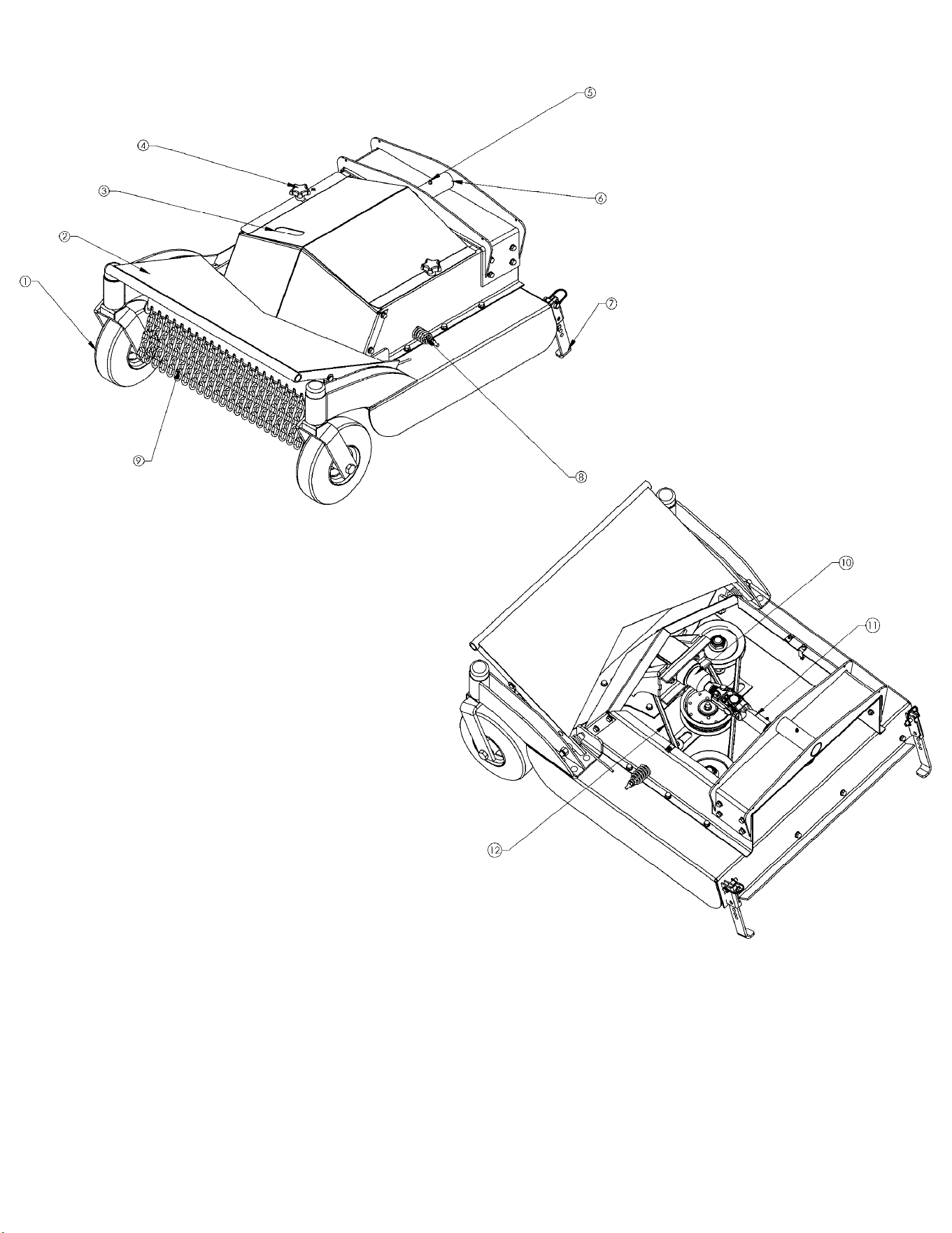
FEATURES
5
5
1 Flat Free Caster Assembly 7 Deck Storage Stand
2 Pivoting Brush Guard 8 Deck Belt Idler Adjustment
3 Tooless Belt Cover 9 Floating Chain Debris Guard
4 Belt Cover Fasteners 10 Heavy Duty 90° Gearbox
5 Pivot Tube Grease Zerk 11 Quick Disconnect PTO
6 Pivot Tube 12 Heavy Duty 5/8" Deck Belt
꽆 ߾
ʂ
ذ
SAFETY INSTRUCTIONS
These instructions are for your safety. Read them thoroughly & carefully.
This Safety Alert Symbol indicates important messages in this manual. When you see this
symbol, carefully read the message that follows and be alert to the possibility of personal
injury.
6
6
Remember: The operator is responsible for
avoiding dangers or accidents.
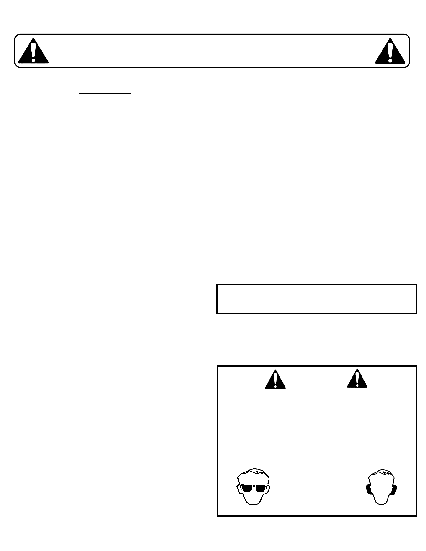
WARNING
When using the machine, approved personal
protective equipment shall be used. Personal
protective equipment cannot eliminate the risk of
injury, but it will reduce the degree of injury if an
accident does occur. Ask your retailer for help in
choosing the right equipment.
Inspect the attachment and tractor before each use.
Make sure all hardware is in place and tightened
properly.
Make sure this attachment is in good operating
c
ondition and properly connected and secured.
Check and double check that the drive line PTO locking
collar moves freely and is securely engaged to the
tractor’s PTO groove.
Never use the machine when barefoot. Always wear
protective shoes or boots.
Always wear protective glasses or full visor and hearing
protection when assembling or operating.
Never wear loose clothing that can get caught in
moving parts.
Check that any safety or informational decals are in
place and legible. Replace any damaged decals.
Safety instructions continued on next page.
General Use:
Read all instructions in this operator’s manual and on
the machine before starting it. Ensure that you
understand them and then abide by them.
Learn how to use the machine, operate its controls
s
afely, how to stop quickly and recognize safety decals.
DO NOT use this machine without the tractor in
place and both machines properly connected.
Only allow the machine to be used by adults who are
familiar with its use and operation.
Make sure nobody else is in the area of the machine
when you start the engine, engage the drive or operate
the machine.
Stop the machine if someone enters the work area.
Clear the area of any objects such as stones, toys, etc.
that may be caught or thrown by the blades.
DO NOT use this machine without the Guards or
Belt Covers in place.
Stop the engine and disconnect the spark plug before
performing maintenance checks.
Never attempt to inspect the PTO shaft with the engine
running and always remove the ignition key and spark
plug wires before clearing debris.
Never take passengers. The machine is only intended
for use by one person.
Always look around before and during reversing
m
aneuvers.
Slow down before turning.
Disengage the blades when not mowing.
Be careful when rounding fixed obstacles so that the
blades do not hit them.
Keep the machine a safe distance from holes or other
irregularities in the ground.
Never use the machine if you are tired, if you have
consumed alcohol or if you are taking other drugs or
medications that can affect your vision, judgment or
coordination.
Beware of traffic when working near or crossing a road.
Never leave the machine unsupervised with the engine
running.
Always disengage the blades, engage the parking
brake, stop the engine and remove the ignition key
before leaving the machine.
Never allow children or other persons not trained in the
use of the machine to use or service it. Local laws may
regulate the age of the user.
Make sure that you have first aid equipment close at
h
and when using the machine.
Always make sure long hair is not left down when
servicing and/or operating the machine. Make sure hair
is out of the way of any moving parts or pinch points.

7
7
SAFETY INSTRUCTIONS
These instructions are for your safety. Read them thoroughly & carefully.
This Safety Alert Symbol indicates important messages in this manual. When you see this
s
ymbol, carefully read the message that follows and be alert to the possibility of personal
injury.
Children:
Children are often attracted to the machine and mowing
work. Serious accidents may occur if you fail to be on
guard for children in the area of the machine.
Never assume that children will stay put where you last
saw them.
Keep children away from the mowing area and under
c
lose supervision by another adult.
Shut off the machine if children enter the work area.
Never allow a child to ride with you.
Never allow children to operate the machine.
Be extra cautious near corners, bushes, trees or other
objects that block your view.
Slope Operation:
Remove obstacles such as stones, tree branches, etc.
Mow side to side , not up and down. Never drive the
mower on terrain that slopes more than 15 degrees.
Avoid starting or stopping on a slope. If the tires begin
to slip, disengage the blades and drive slowly down the
slope.
Always drive evenly and slowly on slopes.
Do not make sudden changes in speed or direction.
Avoid unnecessary turns on slopes. If it becomes
necessary, turn slowly and gradually downward if
possible.
Watch for holes, ruts or bumps. On uneven terrain, the
m
achine can tip more easily. Long grass or other debris
can hide obstacles.
Drive slowly and use small movements of the steering
controls.
Do not mow wet grass. It is slippery, and the tires can
lose their traction, allowing the machine to slide.
Mowing Safety:
Before using, always visually inspect to see that the
blades, blade bolts and cutter assembly are not
worn or damaged. Replace worn or damaged blades
and bolts in sets to preserve balance.
On multi-bladed machines, take care as rotating one
blade can cause other blades to rotate.
Before using, always visually inspect to see that all
bolts and nuts are secure.
Never mow in the direction of people or property.
Debris could be thrown out of the front that can cause
serious injury and property damage.
Maintenance & Storage
:
Keep all nuts, bolts and screws tight to be sure the
equipment is in safe working condition.
If storing equipment over long periods of time remove
all grass clippings, grass build up and debris from the
equipment to prevent corrosion.
Replace worn or damaged parts for continued safe
o
peration.
When machine is to be parked, stored or left
unattended the parking brake should be set.
Remove the ignition key to prevent unauthorized
use.
Training:
All users should seek and obtain
professional and practical instruction.
Such instruction should emphasize:
The need for care and concentration when working with
ride-on or walk-behind machines.
How to properly connect and disconnect the tractor and
attachment.
How to properly drive, control and operate a ride-on or
walk-behind machine with an attachment connected.
Operation Safety:
Do not operate the machine in a confined space.
Always disengage PTO, set parking brake, turn the
engine off and remove the key when leaving the
machine during operations.
Never direct discharge of material toward bystanders or
allow anyone near the machine while in use.
Never operate the machine near bodies of water,
retaining walls, cliffs or tall curbs. Give the machine
ample room to operate and turn around.
Never operate the machine with defective guards or
without safety protective devices in place.
Disengage the PTO switch, set the brake, stop the
engine, remove the ignition key and disconnect the
spark plug wires:
Before clearing blockages.
Before checking, clearing or working on the
machine.
After striking a foreign object, inspect the
machine for damage and make repairs before
restarting and operating the equipment.
If the machine starts to vibrate abnormally (check
i
mmediately).

ӯ
SYMBOLS & DECALS
No Step Decal - OD11
8
8
Serial # ID Tag
Danger / Entanglement - 19486
Triangle Danger Decal - OD55
This Safety Alert Symbol indicates important messages in this manual. When you see this
symbol, carefully read the message that follows and be alert to the possibility of personal
injury.
Spinning Blades Decal – OD29

UNCRATING AND ASSEMBLY
PTO Shaft
Locking Collar
Pivot Shaft
Stand
9
9
Tools Required:
• Tire pressure gauge
• Nail bar or claw hammer
• Wire snips
• Protective eyewear
To remove the VRC30 from the crate:
Position crate on a flat, level surface
D
ispose of top and side panels of the crate.
Remove packing material.
Cut any banding or strapping that may be holding the unit to the
crate.
Remove and dispose of all wheel chocks that are holding the
unit in place.
Carefully push the attachment off the crate to a safe and level
area to connect to the tractor. Alternatively, the attachment can
be connected by rolling or driving the tractor up to the
attachment while still on crate base and once pinned driving the
attachment off of the crate base.
Read all operating instructions, safety instructions, and
customer responsibilities before operating this machinery.
Connecting and Disconnecting Implements
Always make sure that the tractor and attachment are both
on flat ground before attempting to connect or disconnect
the units.
Always check that there are no children around that can be
harmed when connecting or disconnecting units.
Always check that there are no other persons around the
immediate area that could potentially activate the tractor.
Connecting
1. Remove any covering necessary on the attachment.
2. Roll or drive the tractor into the attachment by inserting the
pivot shaft into the pivot tube of the attachment. It may be
necessary to assist the connection by applying the brake to
the tractor and sliding the attachment onto the shaft.
3. Once connected, secure the attachment by installing
locking collar and pin onto the pivot shaft.
4. Connect PTO shaft if provided.
5. Replace any guards and plug in wiring harness.
Disconnecting
1. Make sure the brake on the tractor is on and the PTO is
disengaged before attempting to disconnect the unit.
2. Remove any covering necessary on the attachment and
disconnect the PTO shaft from the tractor if provided.
3. Unpin the locking collar and remove from the pivot shaft.
4. Carefully slide the tractor and attachment apart. The tractor
can be running and driven away from the attachment if
necessary.

Operator Presence System:
Be sure to check that the operator presence and
interlock systems are working properly before every
use. If your mower does not function as described,
repair the problem immediately.
The Control Levers must be in the neutral position in
order for the machine to start. If the controls are not
exactly at neutral the unit will not start.
The attachment wiring harness must be connected in
order to run the PTO system. If it is not properly or
securely connected, the PTO will not engage.
Tires:
Keep tires free of gasoline, oil or insect control
chemicals which can harm rubber.
Avoid stumps, stones, deep ruts, sharp objects and
other hazards that may cause tire damage.
Blade Maintenance:
For best results, mower blades must be kept sharp.
Replace bent or damaged blades.
Engage brakes & safely tilt front of mower (SEE
WARNING).
Refer to Service and Adjustments section for
instructions.
V-Belts:
Check V-belts for deterioration and wear before each use
and replace if necessary. Replace belts if they begin to
slip from wear. Refer to Quick Reference and Service &
Adjustment sections of this manual for instructions on
belt part numbers and how to properly replace belts.
CAUTION
Stop engine, apply brakes, and
remove ignition key for safety.
Disconnect spark plug wires. Wear
heavy, thick gloves when holding onto
blade. Avoid the sharp edge of the
blade.
CUSTOMER RESPONSIBILITIES
10
10
Overall Unit Care:
Reduce the risk of fire by removing grass, leaves and
other debris that may accumulate on the machine.
Allow the machine time to cool before cleaning or
putting it in storage.
Wash mower periodically. Clean above and below
deck.
Keep all electrical connections clean and secure.
Driving & Transport on Public Roads:
Check applicable road traffic regulations before driving
and transporting on public roads.
If the machine is transported, you should always use
approved fastening equipment and ensure that the
machine is well anchored to the towing vehicle.
The cutting deck should also be lowered to the lowest
position and the parking brake engaged during
transport.
WARNING
When it is necessary to tilt the mower
for any repair or service, use safety
chains and/or jack stands to provide
adequate support. DO NOT rely on
hydraulic or mechanical jacks.
WARNING
STOP THE ENGINE AND
DISCONNECT THE SPARK PLUGS
BEFORE MAKING ANY
ADJUSTMENTS TO THE MACHINE!
WARNING
Do not overinflate the tires. Serious
injury can occur if the tire explodes

ӯ
CUSTOMER RESPONSIBILITIES
200 ft. lbs¾-10 BLADE BOLT TORQUE
Side to SideARTICULATION DIRECTION
Splined w/ Spring Loaded Locking Collar, GuardedPTO STYLE
Two Break Away Blade AssembliesBLADES
FRONT: 9X3.50-4 Flat FreeTIRE SIZE
Approximately 4”CUTTING HEIGHT
30”CUTTING WIDTH
LENGTH: 38.5”
WIDTH: 35”
HEIGHT: 19”
WEIGHT: 243lbs
UNIT MEASUREMENTS
75 ft. lbsCENTER ½-20 SPINDLE BOLT TORQUE
11
11
Specifications
M
aintenance Schedule
X
2
Grease Pivot Tube
XX
2
Grease PTO Shaft Joints
XC
heck Operator Presence
XXX
4
Remove Any Debris
XCheck Belts
X
3
Sharpen/Replace
Mower Blades
XXXCheck for Loose Fasteners
Before
Storage
Season100 Hours50 Hours25 Hours8 HoursBefore
Each
Use
1 – Change more often when operating under a heavy load or in high ambient temperatures.
2 – Service more often when operating in dirty or dusty conditions.
3 – Replace blades more often when mowing in sandy soil.
4 – Clean off more frequent when mowing in tall or dry grass conditions or with excessive debris.

䈀
;
OPERATION
12
12
WARNING
Carbon Monoxide. A running engine gives
o
ff carbon monoxide, a poisonous gas
that can kill you. Do not operate the
engine in an enclosed area. Only operate
in a well ventilated area.
Operating the Brush Mower
Before operating this attachment make sure you are
familiar and comfortable with the tractor controls and
operation and have read the tractor owner’s manual.
Make sure there are no bystanders in the area. Flying
d
ebris could cause serious injury.
It is recommended to first drive around in a clear level
area to become familiar with the operation and feel of
the machine without the blades engaged. This machine
is heavy and will effect maneuvering at different
speeds.
The correct ground speed for cutting depends on the
terrain conditions and material density. Traveling too
fast can cause a loss of control and poor cutting
performance.
Always be aware of your surroundings while operating
the cutter. If operating near trees or tall brush be
mindful of overhead dangers such as dead limbs falling
on to the operator. Avoid areas where falling debris is a
danger.
This brush cutter is capable of cutting down trees up to
3 inches in diameter. Make sure you know which way
trees will fall so they do not fall on top of you!
Inspect the area to be cut for utilities, rocks, fences,
f
ence posts or any other objects you do not intend to
cut or it could cause damage to the brush mower.
Before approaching the area to be cut, engage the
blades and make sure they are up to cutting speed.
It is best to engage the PTO drive in areas that have
been cut already or do not contain tall grasses and
weeds. Shut off the ignition and remove the spark plug
wires before clearing debris wrapped on the PTO shaft.
Do not operate until the debris has been removed to
prevent damage to the shaft.
If the blade speed slows down while cutting, slow down
your travel speed and allow the blades to regain the
proper rotating speed.
Starting
Before starting the tractor, be sure the area is clear
of any people or animals.
Control handles must be in the neutral lockout
position.
PTO switch must be in the disengaged
position (pushed down).
Turn ignition key until engine starts. If the
engine struggles to start, engage the choke
until the engine fires, then disengage the
choke before operating.
Once started, increase the engine RPM to desired
s
peed.
.
멀
Ӟ
SERVICE & ADJUSTMENTS
13
13
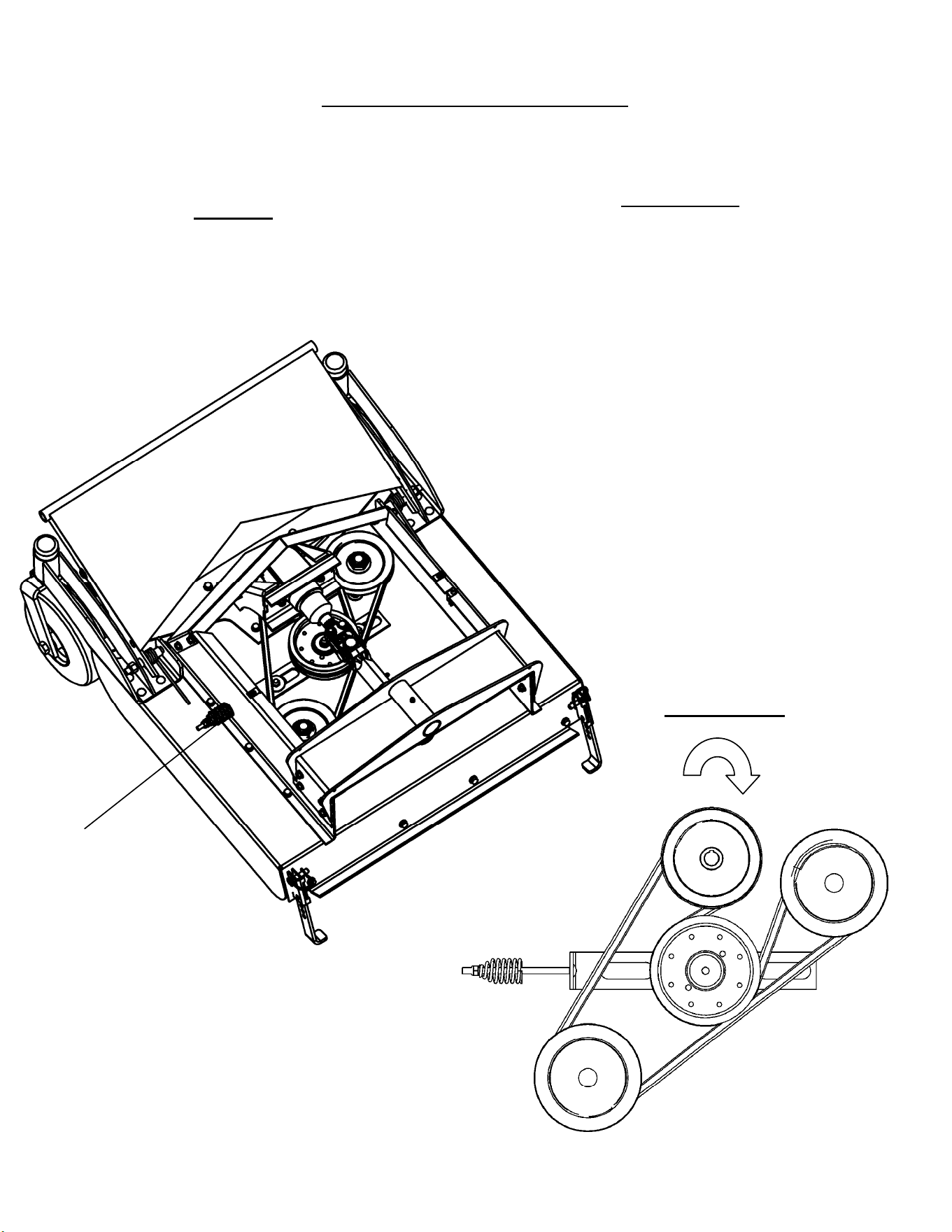
Deck Belt Routing & Replacement
For replacement belt part number refer to Replacement Parts Quick Reference Chart in this manual.
Idler Adjustment
Belt Routing
Removal
Apply parking brake.
Turn off machine and disconnect spark plug wires.
Release the tensioning idler by loosening the nut on the
i
dler assembly bolt.
Once loose, remove the belt from the deck.
Replacement
Install new belt by placing it around all pulleys. Refer to
routing diagram below.
The belt should be loose at this time.
Return tension to the belt by tightening the idler until
s
pring begins to compress and belt has sufficient
tension..
Reconnect the spark plugs.
콆 ߾
ʂ
ذ
SERVICE & ADJUSTMENTS
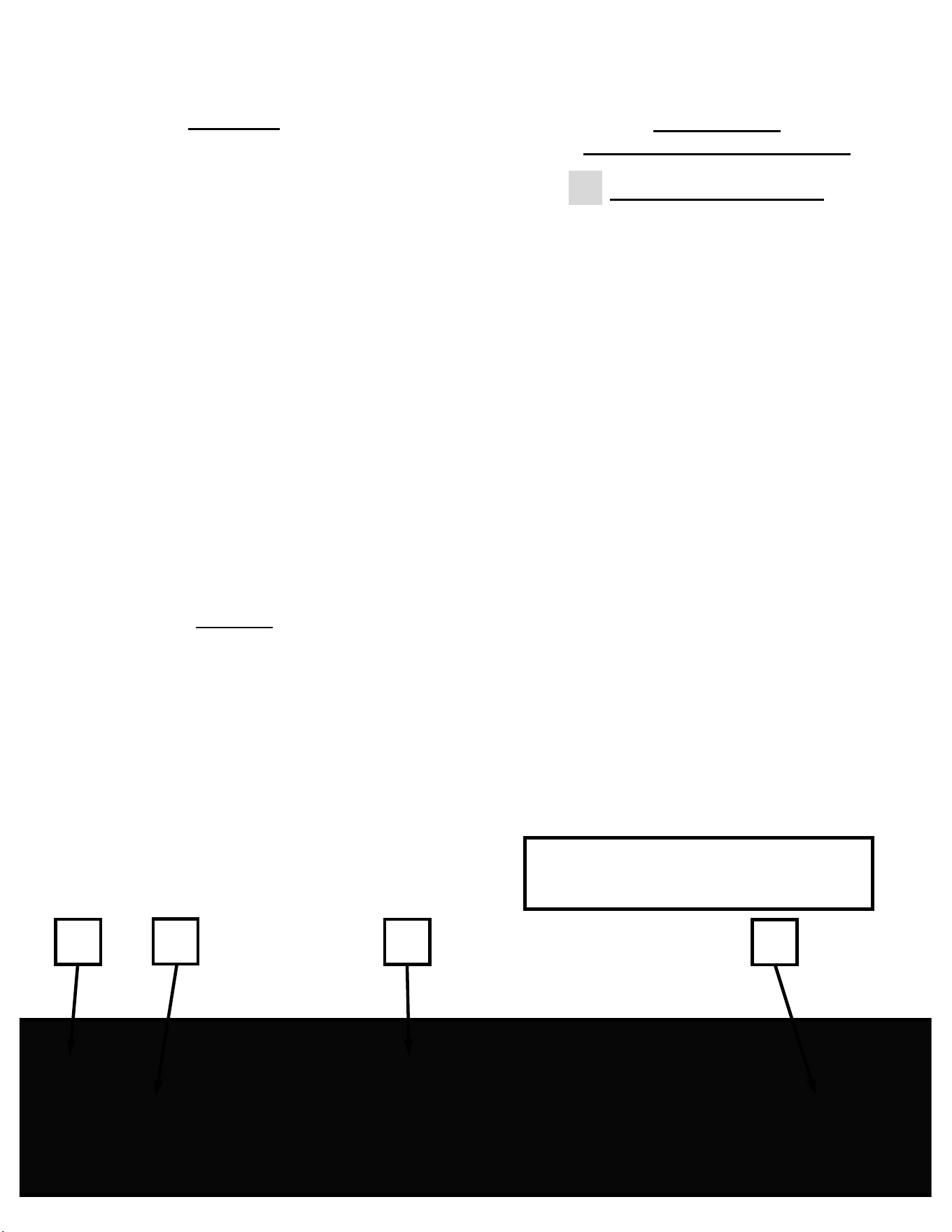
PTO Shaft
Before every use, check to make sure the PTO shaft is
securely attached to both the tractor and attachment
gearboxes.
Before every use, check the PTO shaft u-joints to make
sure they are not damaged or worn. Simply lift up and
down on the shaft when it is securely connected to both
pieces of equipment. If there is excessive movement
then the PTO shaft may need to be replaced.
If there is excessive vibration during operation,
d
isengage the PTO switch, set the brake, stop the
engine, remove the ignition key and disconnect the
spark plug wire(s) and immediately inspect the PTO
shaft. Refer to Troubleshooting section.
It is recommended to grease all PTO Shaft joints every
8 hours (50 hours for extended intervals).
Lubricate all fittings with a good quality lithium soap
compatible EP grease meeting the N.L.G.I. #2
specification and containing no more than 1%
Molybdenum Disulfide.
An EP grease meeting the N.L.G.I. #2 specification and
containing 3% Molybdenum Disulfide may be
substituted in the telescoping members only.
14
14
2
2
1
3
1. Telescoping Shaft Grease Point
2. U-Joint Grease Point(s)
3. Sliding Locking Collar
Gearbox
The gearboxes are lubricated and sealed components.
If used and maintained properly, these gearboxes do
not require lubrication changes.
If there are internal component failures within the
gearbox, it is recommended to replace the entire
gearbox.
However, if the failed internal components are serviced
and/or replaced then new lubrication is required.
This gearbox requires 4 oz. of Bentonite grease. A
recommended brand is Brooks Benalene 900-P-RP.
Mower Blades
Sharpening and Replacement
WEAR HEAVY GLOVES
The blade disc assembly can be removed from the
keyed spindle shaft by removing the center ½” bolt,
washer and ¼” key.
Alternatively the blade disc assembly can be left on the
s
pindle and the individual blades can be removed by
removing the ¾” bolts from the top side of the disc that
hold the blade nuts.
The blades should be professionally sharpened equally
in sets to maintain balance.
The blades are bi-directional and can be turned over to
the unused side between sharpening.
Reinstall the bolts and washers in the reverse order
they were removed or refer to page 20 for assembly
order.
If the entire blade disc assembly was removed it is
recommended to use a thread locking compound on the
center ½” bolt during reassembly.

ɺ
TROUBLESHOOTING
15
15
CorrectionCauseProblem
1. Must be an operator at the operator
position.
2. Ensure the PTO shaft is connected to
the Tractor gearbox.
3. Replace PTO shaft.
4. Tighten or replace deck belt.
5. Tighten or replace engine-to-gearbox
belt.
6. Ensure clutch wiring is properly
connected to clutch and harness.
7. Replace clutch.
1. Operator presence not engaged.
2. PTO shaft not connected to Tractor
Gearbox.
3. Bent or Damaged PTO shaft.
4. Loose or damaged deck belt.
5. Loose or damaged engine-to-
gearbox belt (Tractor).
6. Loose or faulty clutch wiring harness.
7. Faulty clutch.
No Power To
Blades
1. Replace blade(s); Tighten blade bolt.
2. Clean underside of mower deck.
3. Replace blade driver assembly or
components.
1. Worn, bent or loose blade(s).
2. Buildup of debris under deck.
3. Faulty /damaged blade driver
assembly or components.
Poor Cutting
Performance
1. Replace faulty fuse.
2. Ensure wire harness is connected.
1. Faulty fuse.
2. Wire harness not fully connected.
Loss of Power
To Engine
1. Replace blade(s); Tighten blade bolt.
2. Replace blade driver or
component(s).
3. Tighten loose part(s) and/or
hardware; Check for damage.
4. Replace blade driver assembly.
5. Replace or tighten PTO shaft and
any associated hardware.
1. Worn, bent or loose blade(s).
2. Bent or damaged blade driver
component(s).
3. Loose part(s) and/or fastener
hardware.
4. Faulty blade driver assembly.
5. Damaged or loose PTO Shaft.
Excessive
Vibration
1. Make sure control levers are in the
middle of their travel.
2. Charge or replace the battery.
3. Reset circuit breaker at engine.
.
1. Control levers not in neutral position.
2. Battery is undercharged or failing.
3. Circuit breaker on engine tripped.
Engine Will Not
Turn Over
Note: Refer to the tractor manual for more troubleshooting tips that may include other
symptoms or causes not included in this list.

멀
Ӟ
Mower Identification
Each mower has its own model number and
serial number. The number for the attachment
can be found on the back side of the upper belt
surround (refer to Symbols & Decal section for
reference). All mower parts listed herein may
be ordered directly from Swisher or your
nearest Swisher dealer.
WHEN ORDERING PARTS, PLEASE HAVE THE FOLLOWING INORMATION AVAILABLE:
•MODEL NUMBER - __________________________________________________________
•SERIAL NUMBER - __________________________________________________________
•DATE PURCHASED - ________________________________________________________
•PURCHASE FROM - _________________________________________________________
•PART NUMBER (W/ PAINT CODE) - ____________________________________________
•PART DESCRIPTION - _______________________________________________________
www.swisherinc.com
TELEPHONE - 1-800-222-8183
FAX - 1-660-747-3160
S.A.I.
1602 CORPORATE DRIVE
WARRENSBURG, MO 64093
Unauthorized Replacement Parts
Use only Swisher replacement parts. The
replacement of any part on this unit with
anything other than a Swisher authorized
replacement part may adversely affect the
performance, durability and safety of this unit
and may void the warranty. Swisher disclaims
liability for any claims or damages, whether
warranty, property damage, personal injury or
death arising out of the use of unauthorized
replacement parts.
16
16
MOWER IDENTIFICATION

ӯ
REPLACEMENT PARTS
Quick Reference
CAUTION
Use extreme care when working on machinery.
Before performing any maintenance, turn off engine, allow the unit to cool and remove the key.
Disconnect spark plug wire.
Set Parking Brake by
pushing on the brake lever until locked into the “engaged” position.
Do not wear watch or jewelry. Do not wear loose fitting clothes. Observe all common safety
practices with tools.
17
17
Nut – RC Blade2
1366
Housing - RC Blade, Short21371TK
Shaft - PTO, 6E Drive21513
Bearing - Blade, 1"ID X 2"OD4845
Blade - Rough Cut, 5/16" X 6.3"21365
Tire/Wheel - 9X3.50-4
Hollowmatic/Smooth
21515
Belt - V; 5/8" X 76"21555
Part DescriptionSwisher Part #
17
17

ӀӢ
18
18
When Ordering Replacement Parts:
* = USE PAINT CODE: TK=BLACK
CASTER SUPPORTS
㩆
ɺ
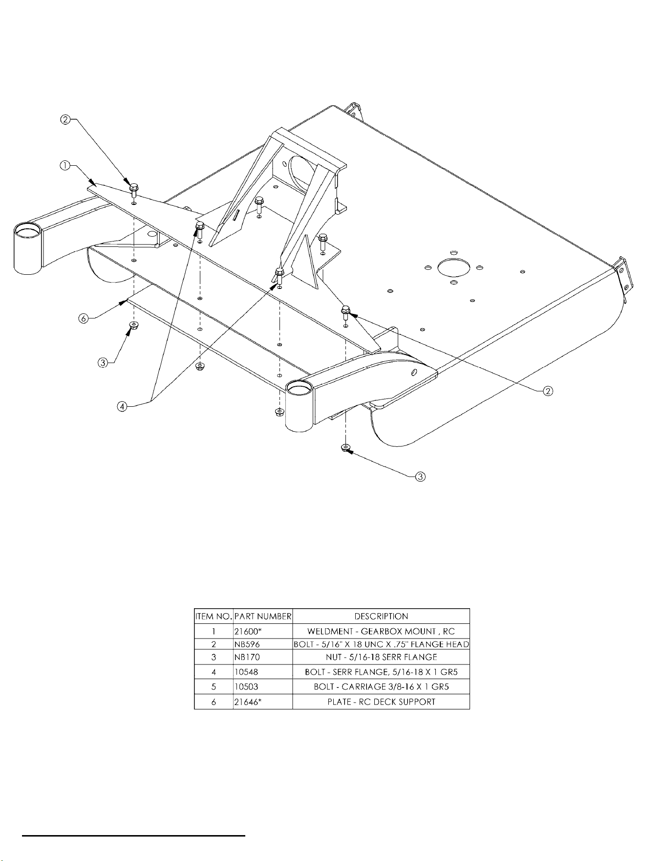
19
19
When Ordering Replacement Parts:
* = USE PAINT CODE: TK=BLACK
GEARBOX MOUNT
ʂذ
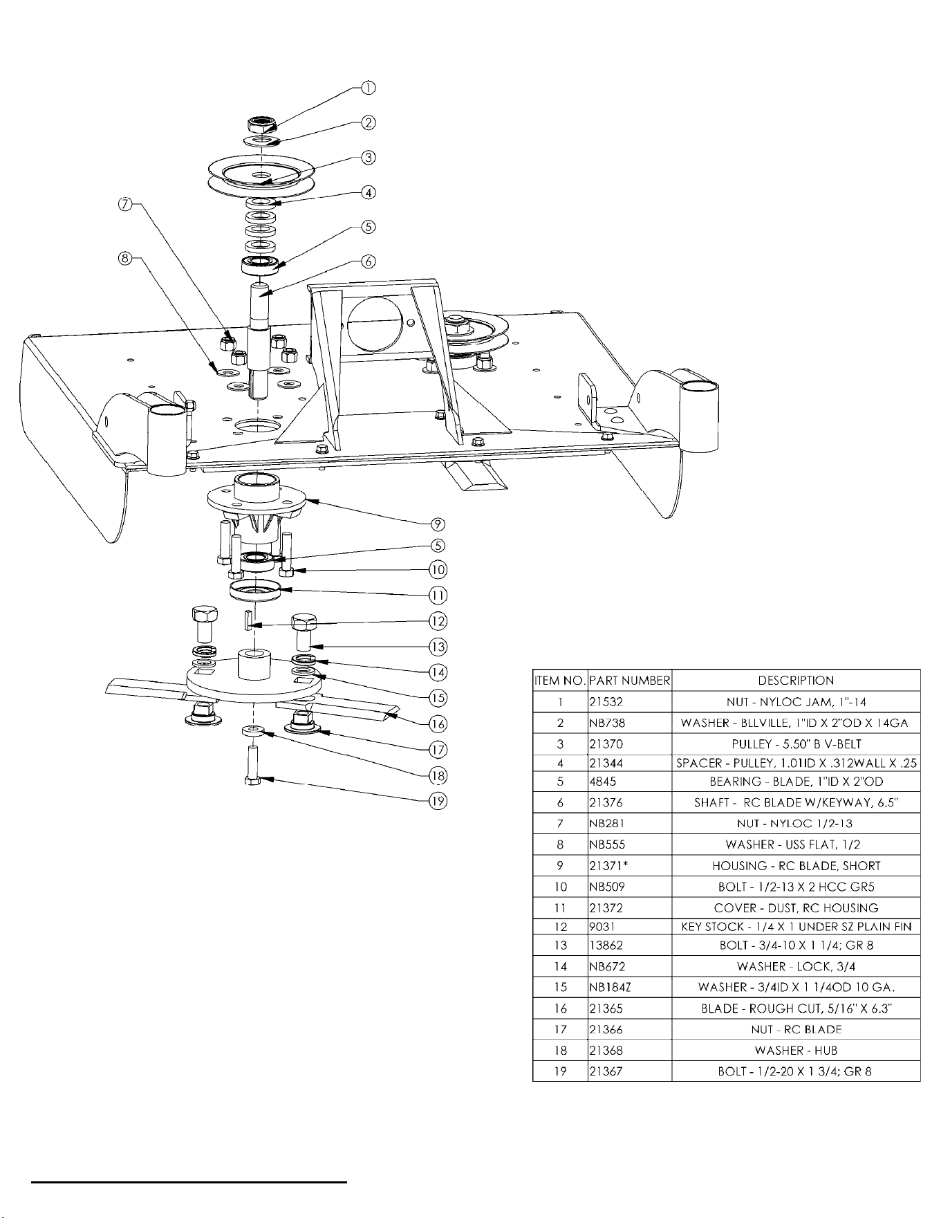
20
20
When Ordering Replacement Parts:
* = USE PAINT CODE: TK=BLACK
BLADE DRIVER ASSEMBLY
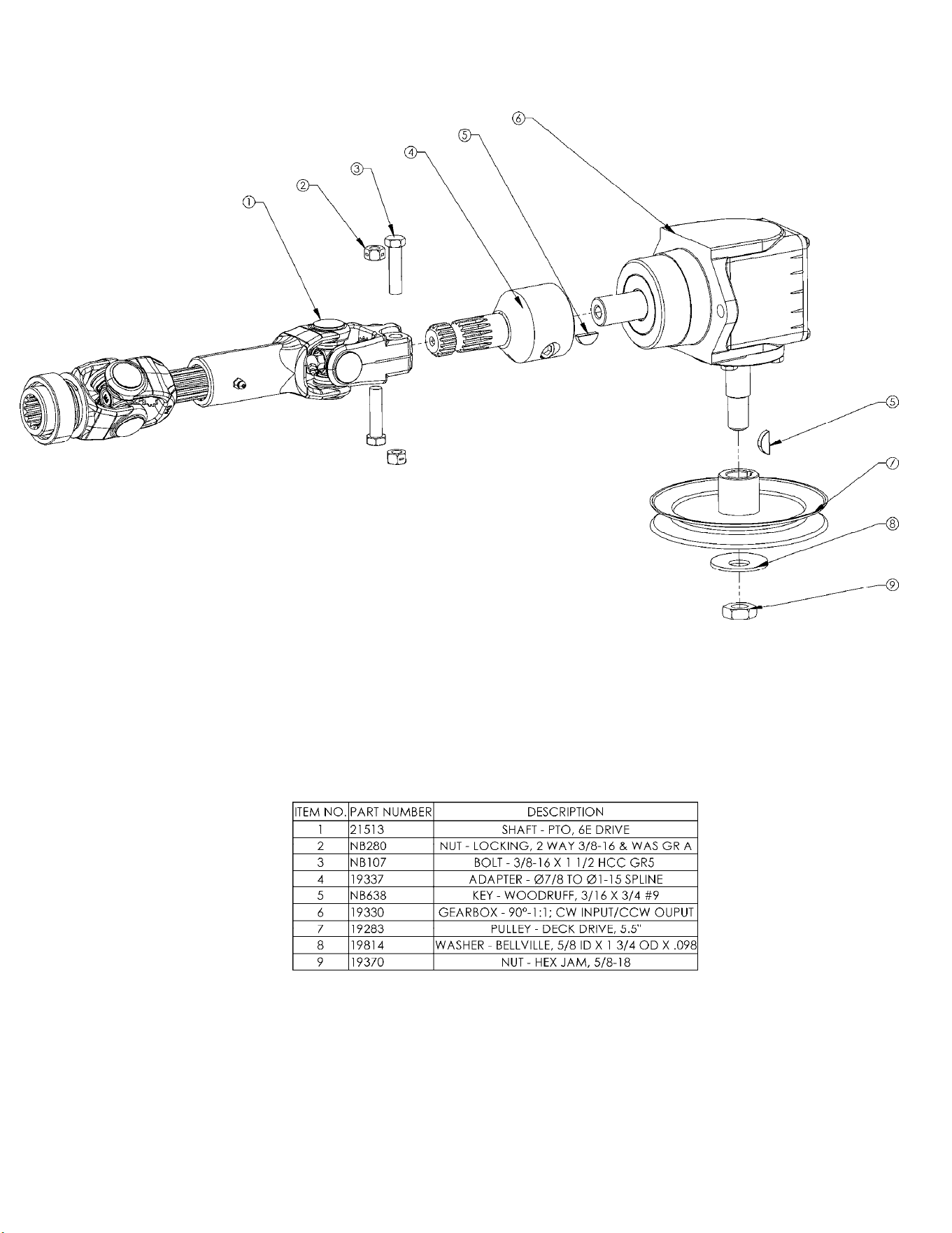
GEARBOX ASSEMBLY
21
21
ʂذ
22
22
When Ordering Replacement Parts:
* = USE PAINT CODE: TK=BLACK
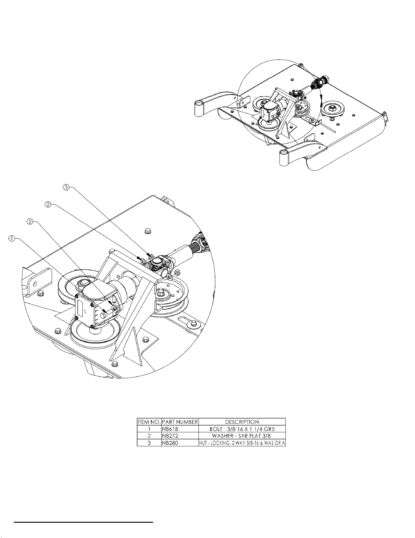
GEARBOX MOUNTING

23
23
When Ordering Replacement Parts:
* = USE PAINT CODE: TK=BLACK
IDLER ASSEMBLY
߾
ʂ
cذ
24
24
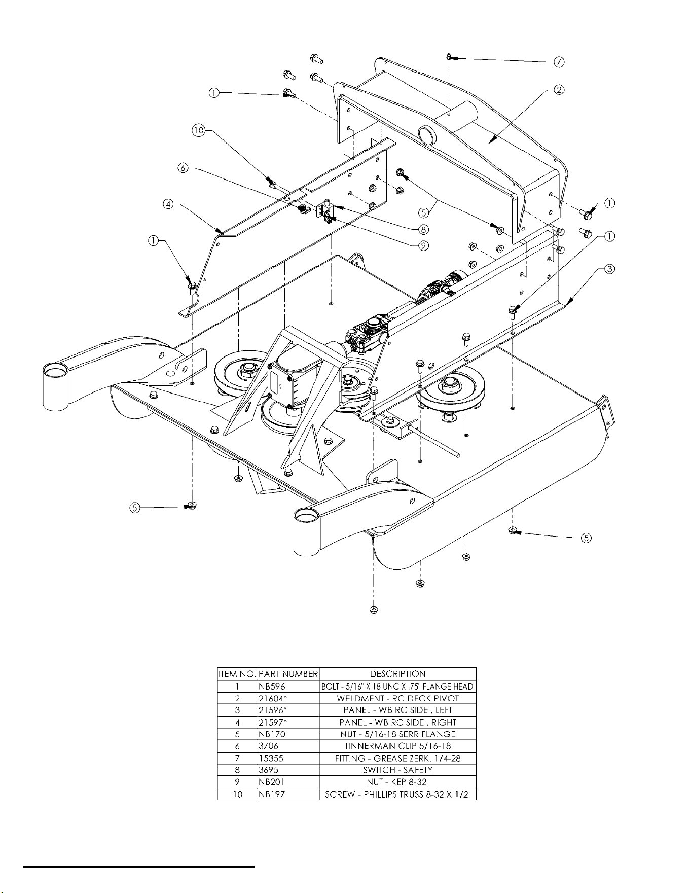
When Ordering Replacement Parts:
* = USE PAINT CODE: TK=BLACK
FRAME
剆
ɺ
25
25
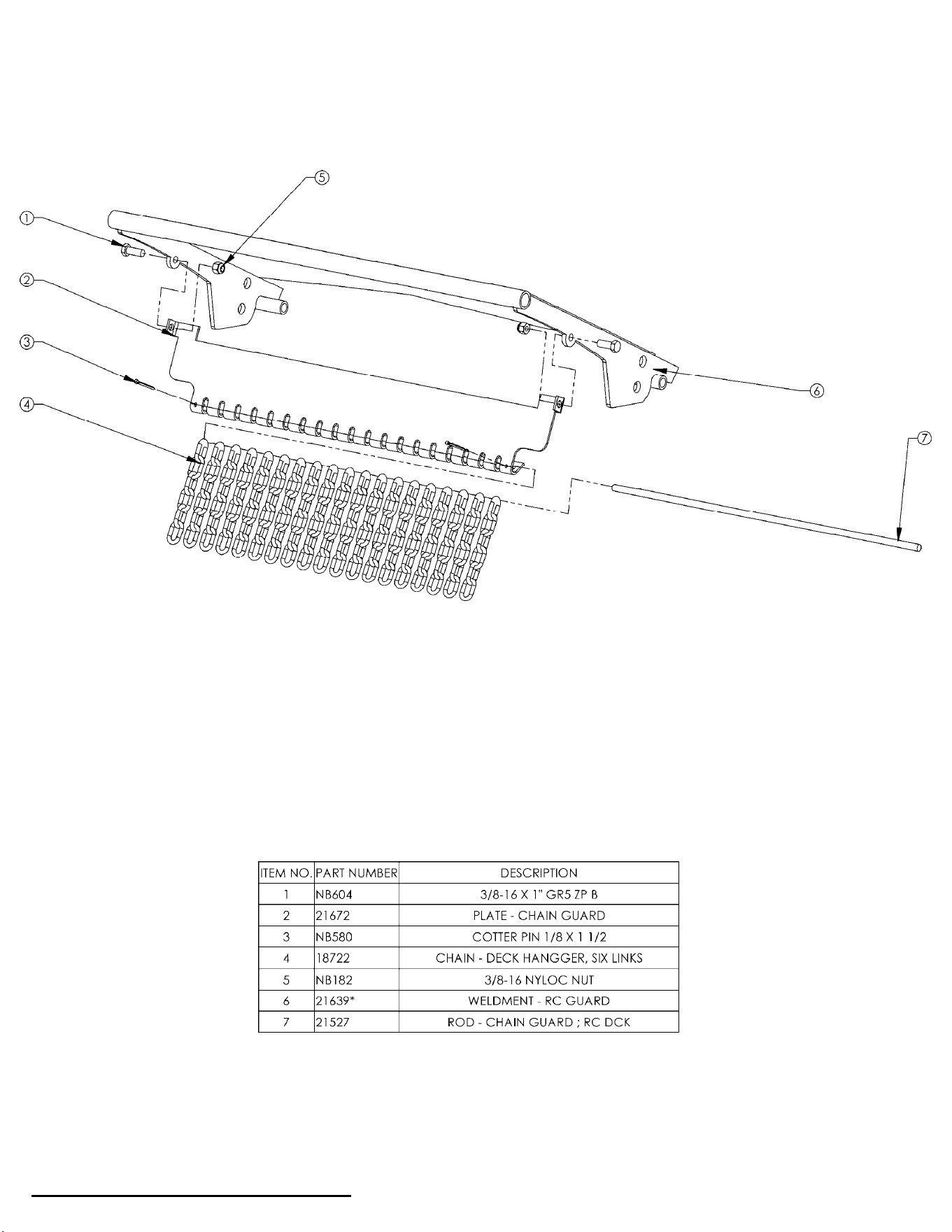
When Ordering Replacement Parts:
* = USE PAINT CODE: TK=BLACK
BRUSH GUARD
݆
◌
ʂ
25
When Ordering Replacement Parts:
* = USE PAINT CODE: TK=BLACK
BRUSH GUARD

27
27
When Ordering Replacement Parts:
* = USE PAINT CODE: TK=BLACK
CASTER ASSEMBLY

ๆ
ʂ
28
28
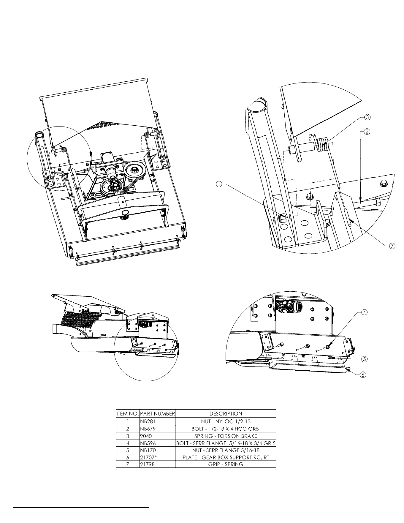
When Ordering Replacement Parts:
* = USE PAINT CODE: TK=BLACK
BELT COVERS / TENSIONER

慆
ɺ
29
29
NOTES

ӣ
Back before electricity came to rural Missouri Max Swisher was producing lawn
mowers from his mother’s chicken house. Max never liked to mow grass. He
installed a gearbox on his family’s lawn mower creating a self-propelled unit. By tying
one end of a rope to the mower and the other end to a tree in the center of the yard
the mower circled the tree, shortening the rope and guiding the mower in concentric
circles. Max enjoyed relaxing under a shade tree while his invention did all the work.
Max had designed his first self-propelled rotary lawn mower to do his dirty work for
him. Neighbors noticed his new invention and began asking him to make more.
Today, over 70 years later, Swisher is still producing innovative lawn and garden and
ATV/UTV equipment designed to give us all more “relaxing in the shade” time.
Swisher products have been featured nationally on television programs such as
Regis and Kathie Lee and seen in publications like ATV Magazine
, Country Journal,
Popular Mechanics Magazine and others. In January 2000 Popular Mechanics
Magazine named Max’s zero turning radius riding mower one of the 20
th
century’s top
household inventions.
Swisher offers value and function in its products to meet your grounds maintenance
needs.
CELEBRATING OVER 70 YEARS OF INNOVATION
SINCE 1945
30
30
SWISHER HISTORY