Loading ...
Loading ...
Loading ...
USING BLADE GUARD ASSEMBLY
The anti-kickback pawls and blade guard
MUST be used for all through-cuts. KEEP both guard shields
down and arms, hands and ngers away from the blade,
blade guard and anti-kickback pawls when power is on to
prevent serious injury. See assembly instructions on page
28 for proper installation and removal of anti-kickback
pawls and blade guard.
If there is a need to briey raise the blade guard (for example, to
make a measurement) the guard can be parked in a raised position.
1. Refer to Figure 44 and, lifting the guard from the front,
raise the guard shield until it snaps into a locked position
above the table. One or both guard shields can be raised.
2. When done making the measurement, return guard to
operating position.
Figure 44
Figure 45
Pivot Pedal
CHECKING FENCE ALIGNMENT
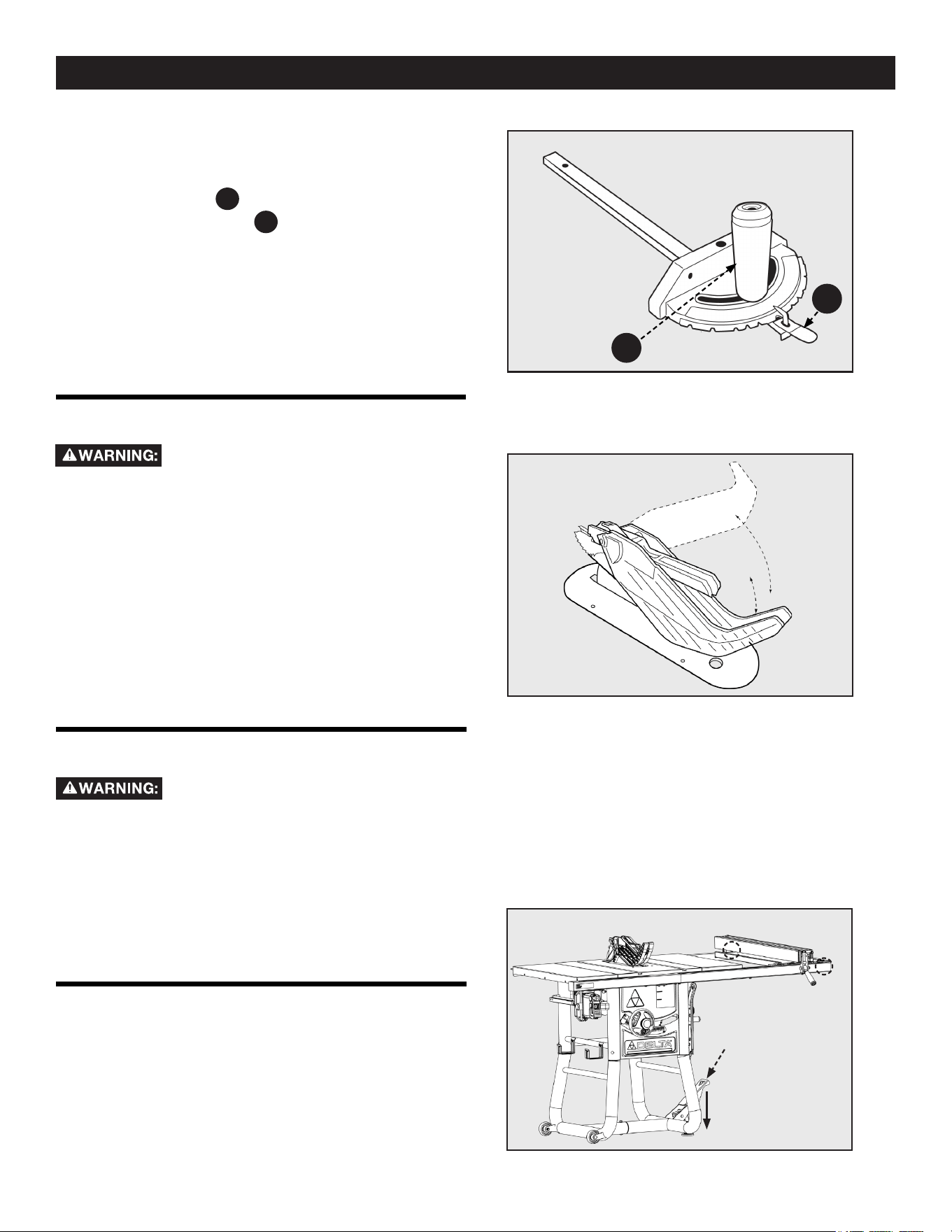
TRANSPORTING THE SAW
DO NOT attempt to use a rip fence that is
not properly aligned.
Every time you use the rip fence, check its alignment to make sure
the fence is parallel to the miter slot. To check the alignment of
your rip fence, place the fence adjacent to miter slot and lock the
fence in place. If the fence is not aligned to the miter slot from the
front to the back, see instructions for aligning rip fence on page
29 of this manual. If you are not able to successfully align the rip
fence, replace the rip fence or call DELTA
®
Customer Service at
1-800-223-7278
NOTE: Make sure the saw is OFF and the blade lowered below the
tabletop and all items are returned to their storage locations before
attempting to move the saw.
To move saw step down on pivot pedal, place hands on each fence
rail, and move saw to desired location. Lift the pivot pedal up after
the saw is moved to desired location. See Figure 45.
PREPARING TO CUT
USING THE MITER GAUGE
The miter gauge is equipped with adjustable index stops at 90°,
75°, 60°, 45° and 30°. To set the miter for an angled cut, see
Figure 43 and:
1. Loosen the handle
A
.
2. Depress the thumb lever
B
.
3. Move the body of the miter gauge to the desired angle
maximum 30° on either side.
4. Release the thumb lever and re-tighten the handle.
The Miter Gauge is equipped with two washers both in the front
and end of the bar, which directly ts into any of the T-slots in the
work table. This allows for the miter gauge to stay in place and
level with the saw's table.
Figure 43
A
B
34
Loading ...
Loading ...
Loading ...