Loading ...
Loading ...
Loading ...
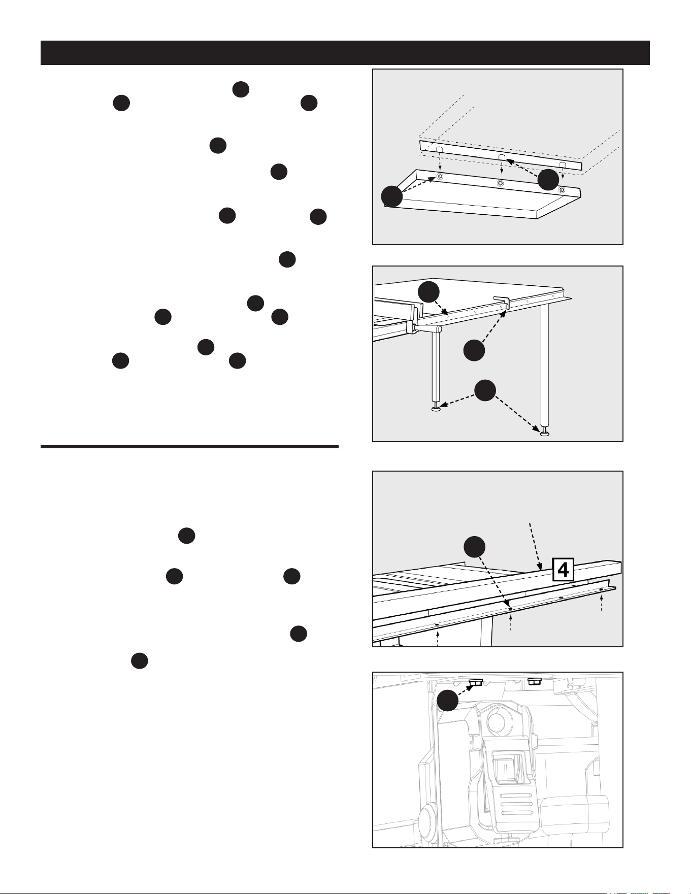
Figure 13
FENCE GUIDE
ASSEMBLY
Figure 14
Figure 15
Figure 12
FENCE GUIDE AND POWER
CONTROL BOX
HP7
HP20
PC22
A
B
C
Hardware Bag “E” for 36-5000T2 and 36-5100T2
Hardware Bag “G” for 36-5052T2 and 36-5152 T2
HP30
5. Loosely assemble three 5/16 18 x 7/8 inch Hex Head
Screws with Split Lock Washers
HP7
, 8 x 16 x 1t Flat
Washers
HP16
and three 5/16-18 Hex Flange Nuts
HP14
into
the three holes into the side of the extension wing as
shown. See Figure 12.
NOTE: The 5/16-18 Hex Flange Nuts
HP14
are only used on the 36-
5052 T2.
6. Carefully lower the slotted wing attachment
PC22
down onto
the screws on the extension wing. Tighten the screws after
the wood table is leveled with the extension wing.
7. Using the Rail Alignment Gauge
HP20
adjust the feet
B
in
the table legs so the top of the table is at the proper
distance from the rail.
8. Drill 1/4 inch holes through the rail holes
A
into the
wood table on the front and back rails. See Figure 13.
9. Fasten Wood Table Extension to Front Rail using six 1/4-20
x 1-1/2 Pan Head Hex Socket Screws
HP17
, 6.74 x 20.63 x
1.58 Flat Washers
HP27
and 1/4-20 Hex Nuts
HP28
.
10. Fasten Wood Table Extension to Rear Rail using six 1/4-20
x 1-1/2 Hex Head Screws
HP26
, 6.74 x 20.63 x 1.58 Flat
Washers
HP27
and 1/4-20 Hex Nuts
HP28
.
1. Attach the fence guide
PC19
to the front rail using four (for
36-5000 T2 and 36-5100 T2) or six (for 36-5052 T2 and
36-5152 T2) 1/4 20 x 1/2 inch Button Head Hex Screw w/
Split Lock Washer
HP18
through the holes
C
on the
bottom side of the front rail.
2. Align the two holes in the switch box bracket with the holes
underneath the front rail, shown in Figure 15, located on
the left side of the saw. Secure the switch box
F3
to the
front rail using two 1/4 20 x 1/2 inch Hex Screw w/ Split
Lock Washer
HP19
.
21
Loading ...
Loading ...
Loading ...