
Technical Support and E-Warranty Certificate www.vevor.com/support
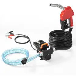
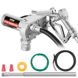
FUEL TRANSFER PUMP
OWNERS INSTALLATION, OPERATION, AND SAFETY MANUAL
MODEL: MX102
We continue to be committed to provide you tools with competitive price.
"Save Half", "Half Price" or any other similar expressions used by us only represents an
estimate of savings you might benefit from buying certain tools with us compared to the major
top brands and doses not necessarily mean to cover all categories of tools offered by us. You
are kindly reminded to verify carefully when you are placing an order with us if you are
actually saving half in comparison with the top major brands.
MODEL: MX102
Have product questions? Need technical support? Please feel free to
contact us:
CustomerService@vevor.com
NEED HELP? CONTACT US!
This is the original instruction, please read all manual instructions
carefully before operating. VEVOR reserves a clear interpretation of our
user manual. The appearance of the product shall be subject to the
product you received. Please forgive us that we won't inform you again if
there are any technology or software updates on our product.
FUEL TRANSFER PUMP

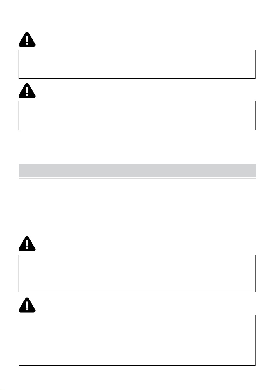
SAFETY INFORMATION
WARNING! Electrical wiring should be performed ONLY by a
licensed electrician in compliance with local, state, and national
electrical codes NEC/ANSI/ NFPA 70, NFPA 30, and NFPA 30A, as
appropriate to the intended use of the pump. Threaded rigid conduit,
sealed fittings, and conductor seal should be used where applicable.
The pump must be properly grounded. Improper installation or use of
this pump can result in serious bodily injury or death!
WARNING! To ensure the safe and proper operation of your
equipment, it is critical to read and adhere to all of the following safety
warnings and precautions. Improper installation or use of this product
can cause serious bodily injury or death!
NEVER smoke near the pump, or use the pump near open flames
when pumping a flammable liquid! Fire can result!
A filter should be used on the pump outlet to ensure no foreign
material is transferred to the fuel tank.
Threaded pipe joints and connections must be sealed with the
appropriate sealant or sealant tape to minimize the possibility of
leaks.
Storage tanks must be securely anchored to prevent shifting or
tipping when full or empty.
To minimize static electricity build-up, use only static wire conductive
hose when pumping flammable fluids, and keep the fill nozzle in
contact with the container being filled during the filling process.
The pump motor is equipped with thermal overload protection; if
overheated, the motor will shut off to prevent damage to the
windings.
WARNING! This product shall not be used to transfer fluids into
any type of aircraft.
WARNING! This product is not suited for use with fluids intended
for human consumption or fluids containing water.
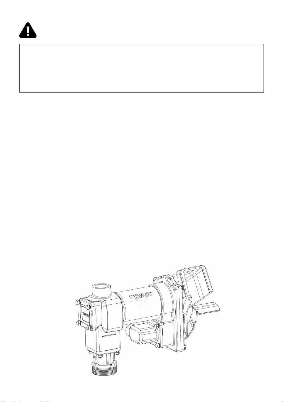
INSTALLATION
16GMP fuel transfer pump is designed to be mounted on a skid tank using
the threaded inlet flange supplied with the pump. Your pump features an
integral bypass valve to recirculate the fluid when the pump is operating
with the nozzle closed.
WARNING! This product is not suited for use with fluids intended
for human consumption or fluids containing water.
CAUTION! Do not use additional check valves or foot valves
unless they have a proper pressure relief valve built into them. Note that
additional check valves will reduce the rate of flow.

CAUTION! A pressure-retaining fill cap can be used to reduce fuel
loss through evaporation, but note that it will reduce the flow rate.
CAUTION! Threaded pipe joints and connections must be sealed
with the appropriate sealant or sealant tape to prevent the possibility of
leaks.
WARNING! 16GMP fuel transfer pumps are designed for use with
stationary and mobile tank applications. While DC-powered units are
excellent choices for mobile applications, anchoring the tank to which
the pump is mounted is paramount to ensure no movement in transit.
Failure to secure the tank to the vehicle can cause uncontrolled
movement, resulting in damage, injury, and potential fire.
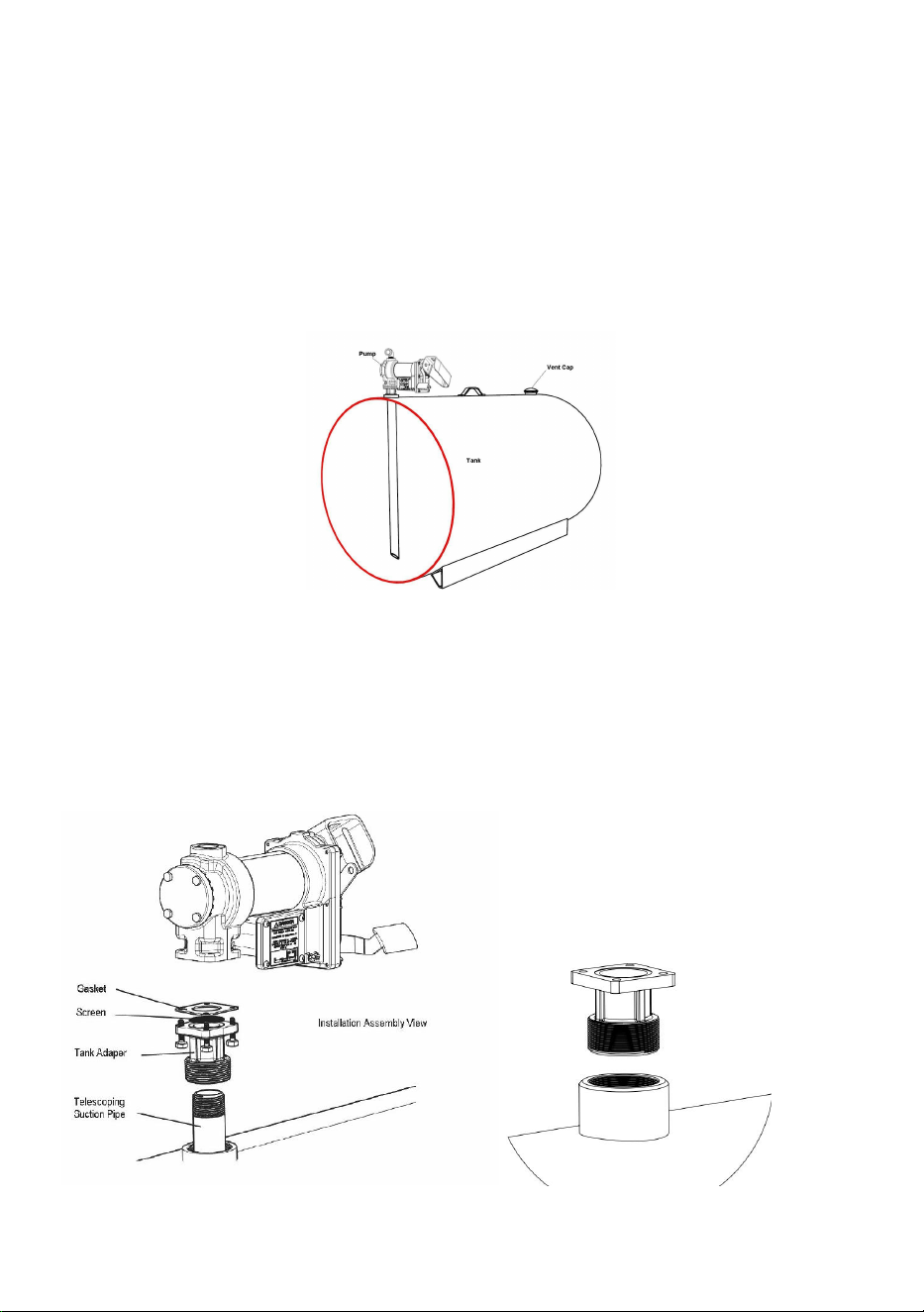
Typical Skid Tank Installation
The pump mounts to the bung of a skid tank by way of the inlet flange. The
suction tube threads into the bottom of the inlet flange and must extend to
a length that positions it at least 3” from the bottom of the tank. The skid
tank should be equipped with a vent cap.
Materials:
1” telescoping suction pipe extended to a length that will extend to
within 3” of the bottom of the tank when screwed into the tank adapter
with the tank adapter screwed into the tank flange (see SKID TANK
INSTALLATION diagram).
Threaded pipe joint sealant appropriate for the application.
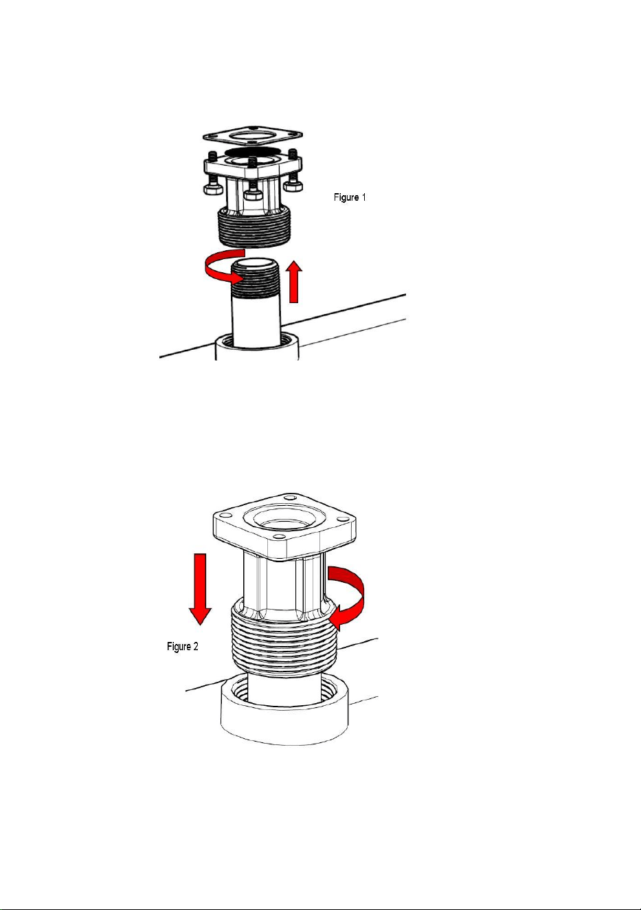
Installation Procedure:
1. Thread the 1” pipe into the tank adapter. Seal threads liquid tight with
appropriate sealant. (Figure 1)
Typical Skid Tank Installation (cont’d)
2. Screw the inlet flange (with suction pipe) into the tank bung; seal
threads liquid tight with appropriate thread sealant (Figure 2).
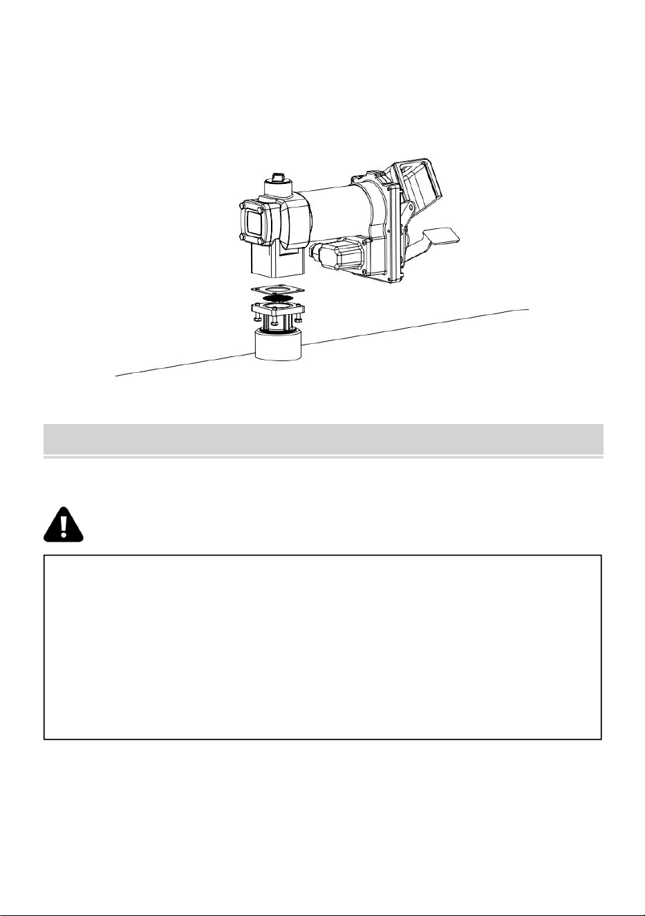
3. Mount the pump on the adapter, making sure the seal and screen are
installed as shown. (Figure 3).
ELECTRICAL WIRING
CAUTION! DC-powered pumps are designed to operate on either
12 or 24 VDC (depending on the model). Where applicable, use the
supplied battery cable to supply power to the pump from a 12 or
24-VDC battery. A 30 amp fuse (20 amp fuse on 24 VDC motors) should
be installed on the battery cable to protect the wire in case of an
electrical short.

CAUTION! Voltage drop-in wiring varies depending on the
distance from the battery to the pump and the gauge of the wire used. If
the distance is greater than 20’, refer to national, international, or local
electrical codes to ensure the wire is of the correct size for this
application.
Instructions Before Proceeding With DC Wiring
The pump needs to be electrically bonded to the supply tank or vehicle
frame. To electrically bond the pump, remove the green bonding screw
located next to the junction box cover. Insert this screw through an eyelet
of furnished green bonding wire assembly and refasten it securely to the
pump. The other end of the wire is to be stripped of insulation, and the bare
wire securely bonded to the vehicle / trailer frame or skid tank.
WARNING! Do not connect the positive or negative power to the
green screw or wire, as this could cause a fire.
Wiring Instructions
1. Remove the pump’s electrical junction box cover and straighten the 2
wires to make
the stripped wire ends accessible outside of the junction box.
2. Screw furnished cable connector into NPT* conduit opening in the
pump junction box.
3. Strip 6 inches of the outer covering from one end of the furnished

electrical cable, being careful not to damage the black and red wire
insulation.
4. Loosen the cable connector nut and pass the stripped end of the
furnished cable through the cable connector. Tighten the cable
connector nut.
5. Strip 1⁄2 inch of the insulation from the ends of the red and black cable
wires. Using the furnished wire nuts, connect these wires to the pump
wires matching the colors. Be sure no bare wire is exposed.
6. Fold wires into the junction box and replace the cover making sure the
gasket is in place. Make sure all screws are seated, so there is no
space between the cover and the junction box.
Wiring To A Vehicle Electrical System
1. Pass the electrical wires to the source of the vehicle power system,
supporting the wires as necessary and protecting them from sharp
edges, heat, and anything that could damage the wires.
2. To determine if the vehicle's electrical system is negative (-) or positive
(+) ground, check the battery marking of the terminal that is wired to
the vehicle frame or motor block. The red wire from the pump will
connect to the positive battery post, and the black wire from the pump
will connect to the negative battery post.
3. Attach one end of the fuse holder to the end of the ungrounded wire.
Make a solid electrical connection with the other end of the fuse holder
to the ungrounded side of the battery, as close to the battery as
possible. Make a solid electrical connection to the grounded side of the
battery with the remaining wire. The battery terminal or the end of the
battery cable is recommended.
4. Check all connections to make sure they are connected per
instructions and all electrical codes. Install the 30 amp fuse (20 amp
fuse in 24 VDC installations) in the fuse holder. The installation is now
complete.
WARNING! Do not attempt to power the pump from vehicle wiring
smaller than 12 gage, such as the cigarette lighter wire, because these
thin wires could overheat and cause a fire.
DC Wiring (cont’d)
For Skid Mounted Tanks
1. Pass the electrical wires to the power source, supporting the wires as
necessary and protecting them from sharp edges, heat, and anything
that could damage the wires.
2. Attach one end of the fuse holder to the red pump wire, as close to
the battery /power source as possible. Make a solid electrical
connection to the positive terminal of the power source with the other
end of the fuse holder. Make a solid connection with the black pump
wire to the negative terminal of the power source.
3. Check all connections to make sure they are connected per
instructions and all electrical codes. Install the 30 amp fuse (20 amp
fuse in 24 VDC installations) in the fuse holder. The installation is now
complete.
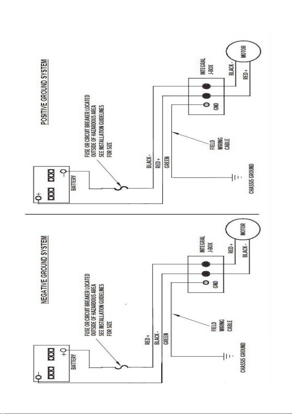
DC Wiring Diagram
OPERATING INSTRUCTIONS
WARNING! Always keep the nozzle in contact with the container
being filled during the filling process to minimize the possibility of static
electricity build-up.
1.If so equipped, reset the meter to “0” (do not reset while in use as this will
cause damage to the meter).
2.Remove the dispensing nozzle from the nozzle boot.
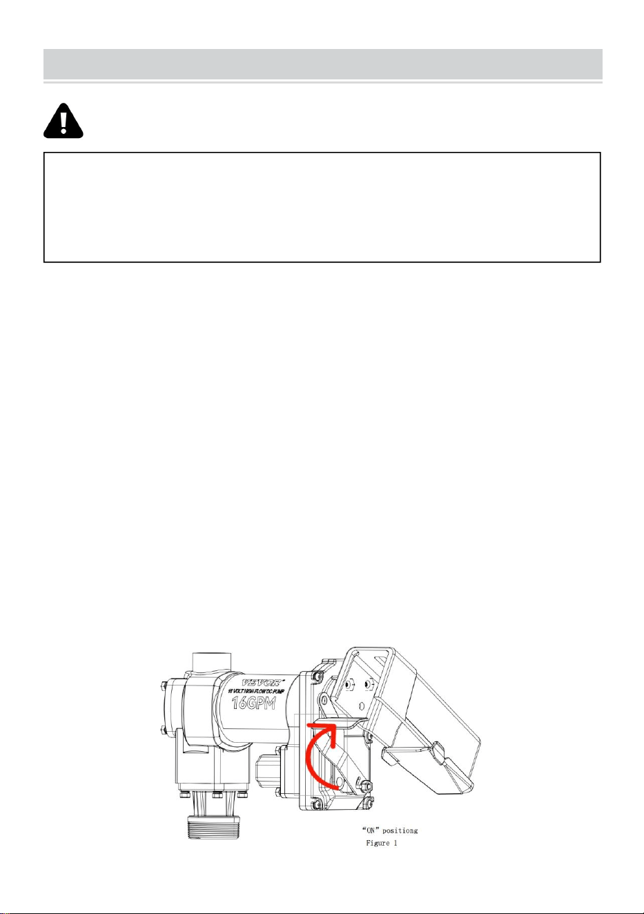
3.Move the switch lever to the “ON” position to power the pump (figure 1).
4.Insert the dispensing nozzle into the container to be filled.
5.Operate the nozzle to dispense fluid; release the nozzle when the
desired amount of fluid has been dispensed.
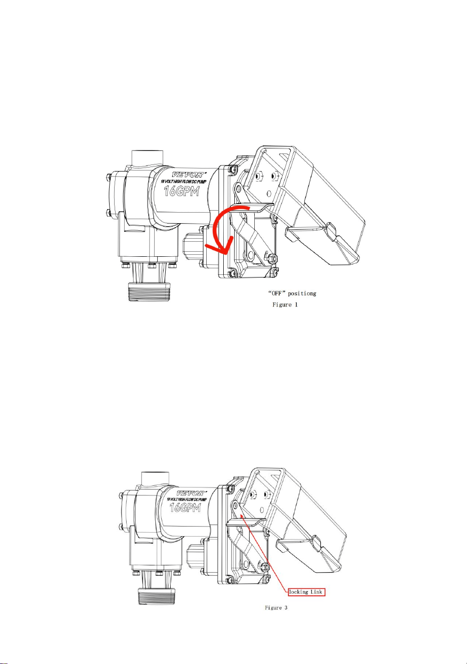
6.Move the switch lever to the “OFF” position (Figure 2) to turn off the
pump.
7.Remove the dispensing nozzle from the container being filled and store it
in the nozzle boot.
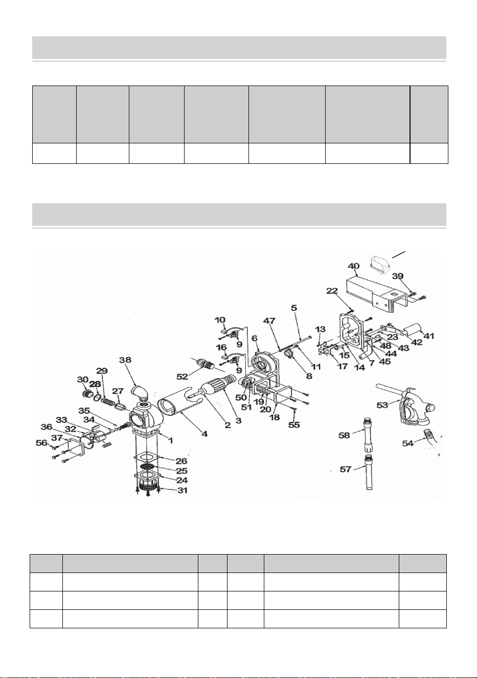
Padlocking
Your pump nozzle can be padlocked to the pump for added security. With
the pump turned off and the nozzle in the stored position, a padlock can be
inserted through the locking link and the nozzle handle.
The locking link is located on the nozzle side of the pump and can be
pivoted into position to work with a variety of nozzles (Figure 3).

TROUBLESHOOTING
The following troubleshooting guide is provided to offer basic diagnostic
assistance in the event you encounter abnormal service from your 20GMP
fuel transfer product.
WARNING! DO NOT open or attempt to repair the motor on your
pump. Return it to the place of purchase for service. Opening the motor
case can compromise the integrity of the Explosion Proof construction
and will void any existing warranty and certification.
WARNING! Be certain all power to the pump is disconnected prior
to performing any service or maintenance.

Symptom
Cause
Cure
Pump won't
prime.
1. Suction line problem.
Check for leaks or obstructions in the suction line.
2. Bypass valve open.
Remove and inspect the valve; must move freely
& be free of debris.
3. Vanes sticking.
Check vanes and slots for nicks, burrs, and wear.
4. Excessive rotor or vane
wear.
Inspect rotor & vanes for excessive wear or
damage; replace if necessary.
5. Vapor Lock.
Reduce vertical and horizontal distance from
pump to liquid; remove the automatic nozzle.
Low capacity.
1. Excessive dirt on the
screen.
Remove and clean the screen.
2. Suction line problem.
Check the suction line for leaks or restrictions; it
may be too small, too long, or not airtight.
3. Bypass valve sticking.
Remove and inspect the valve; must move freely
& be free of debris.
4. Outlet blocked.
Check the pump outlet, hose, nozzle & filter for
blockage.
5. Vanes sticking.
Check vanes and slots for wear.
6. Excessive rotor or vane
wear.
Inspect rotor & vanes for excessive wear or
damage; replace if necessary.
7. Hose or nozzle damage.
Replace the hose or nozzle.
8. Plugged filter.
Replace filter.
9. Low fluid level.
Fill tank.
Pump runs
slowly.
1. Incorrect voltage.
Check incoming line voltage while the pump is
running.
2. Vanes sticking.
Inspect vanes and slots for nicks, burrs, and wear.
3. Wiring problem.
Check for loose connections.
4. Motor problem.
Return to the place of purchase.

TROUBLESHOOTING (CONT’D)
Motor stalls / fuse
blows or thermal
protector trips
repeatedly.
1. Bypass valve sticking.
Remove and inspect the valve; must move
freely & be free of debris.
2. Low voltage.
Check incoming line voltage while the pump
is running.
3. Excessive rotor or vane wear.
Check the rotor & vanes for excessive wear
or damage.
4. Debris in pump cavity.
Clean debris from the pump cavity.
Motor overheats.
1. Pumping high-viscosity fluids.
These fluids can only be pumped for short
periods of time (less than 30 minutes duty
cycle).
2. Clogged screen.
Remove and clean the screen.
3. Restricted suction pipe.
Remove and clean the pipe.
4. Motor failure.
Return to the place of purchase.
5. Pump rotor lock-up.
Clean and check the pump rotor and vanes.
Motor
Inoperative.
1. No power.
Check incoming power.
2. Switch failure.
Replace switch.
3. Motor failure.
Return to the place of purchase.
4. Thermal protector failure.
Return to the place of purchase.
5. Incorrect/loose wiring.
Check the wiring.
Fluid leakage.
1. Bad o-ring gasket.
Check all o-ring gaskets.
2. Dirty shaft seal.
Clean seal & seal cavity.
3. Bad shaft seal.
Replace seal.
4. Incompatible fluid.
Refer to the wetted parts list to the fluid
manufacturer.
5. Loose fasteners.
Tighten fasteners.
Pump hums but
will not operate.
1. Motor failure.
Return to the place of purchase.
2. Broken rotor key.
Remove all debris & replace the key.
SPECIFICATIONS
Model
Voltage
Input (W)
Flow Rate
(GPM)
Inlet Pipe
Specification
(inch)
Outlet Pipe
Specification
(inch)
G.W.
(kg)
MX102
DC12V
380
16
1
1
15.8
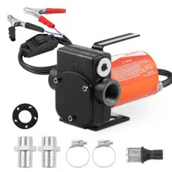
PARTS LIST
REF#
DESCRIPTION
OTY
REF#
DESCRIPTION
OTY
1
PUMP HOUSING
1
34
ROTOR KEY
1
2
BALL BEARING
2
35
ROTOR COVER
1
3
RMATURE ASSEMBLY
1
36
ROTOR COVER GASKET
1
59

4
MOTOR FRAME/MAGNET
ASSEMBLY
1
37
SEAL ASSEMBLY
1
5
1/4-2×5THRU-BOLT
2
38
STEEL ELBOW
1
6
MOTOR CASTING ASSEMBLY
1
39
5/16-18×3/4HHCS
1
7
SWITCH PLATE WITH BUS HING
1
40
NOZZLE COVER
2
8
THERMAL PROTECTOR
1
41
SWITCH LEVER
1
9
BRUSH HOLDER ASSEMBLY
2
42
5/15×18LOVK NUT
1
10
NEGATIVE BRUSH ASSEMBLY
1
43
#14×S/8DRVE SCREW
1
11
#8-32×1/2TORX
1
44
LOCKING LINK
1
12
-
-
45
1/4 SPRING WASHER
1
13
#8-32×3/8 TORX
2
46
ECT LOCK WASHER
1
14
5/16 SPRING WASHER
1
47
-
-
15
SWITCH SHAFT ASSEMBLY
1
48
5/16 RETAINING RING
2
16
POSITIVE BRUSH ASSEMBLY
1
49
GROUND WIRE
1
17
LINE SWITCH
1
50
18
JUNCTION BOX COVER
1
51
#832×3/8 GROUND SCREW
1
19
NEGATIVE WIRE LEAD
1
52
CABLE CONNECTOR
1
20
POSITIVE WIRE LEAD
1
53
NOZZLE
1
21
-
-
54
HOSE
1
22
10-24×3/4 TORX
6
55
10-24×.50TORX
4
23
5/32×1/2PIN
1
56
1/4-20×.5HHCS
4
24
INLET FLANGE
1
57
SUCTION PIPE
1
25
SCREEN
1
58
SUCTION PIPE EXTENSION
1
26
INLET GASKET
1
59
OIL RECEIVING BOX
1
27
BYPASS VALVE
1
28
BYASS VALVE GASKET
1
29
BYPASS SPRING
1
30
BYPASS CAP
1
31
1/4-20×3/4HHCS
1
32
VANE
4
33
ROTOR
5
Made In China