IoT interface
Tasks and Virtual Devices
3124300

Contents
EN
2 Rittal IoT interface – Tasks and Virtual Devices
Contents
1 Tasks ............................................... 3
1.1 General ........................................................ 3
1.2 Tasks tab ..................................................... 3
1.3 Specifying the trigger expression .................. 3
1.3.1 Details group frame ............................................... 3
1.3.2 Delaying a task ...................................................... 3
1.3.3 Trigger Expression group frame ............................ 4
1.4 Selection of an action ................................... 5
1.4.1 "Set Variable Value" action .................................... 5
1.4.2 Grouping of outputs .............................................. 6
1.4.3 "Shutdown Server" action ..................................... 6
1.5 Example for creating a task .......................... 7
1.6 Deactivating or deleting a task ..................... 7
1.6.1 Deactivating a task ................................................ 7
1.6.2 Deleting a task ...................................................... 7
2 Virtual Devices .................................. 8
2.1 General ........................................................ 8
2.2 Types of virtual devices ................................ 8
2.2.1 Two-Level Controller ............................................. 8
2.2.2 Access Controller .................................................. 8
2.2.3 Blue e+ Remote Controller .................................... 8
2.3 Creating a virtual device ............................... 8
2.4 Inputs and Outputs ...................................... 8
2.5 Configuring a virtual device .......................... 9
2.5.1 Two-Level Controller ........................................... 10
2.5.2 Access Controller ................................................ 10
2.5.3 Blue e+ remote controller .................................... 10
2.6 Deleting a virtual device .............................. 13
Rittal IoT interface – Tasks and Virtual Devices 3
1 Tasks
EN
1Tasks
1.1 General
The tasks can be used to query the status of all connect-
ed components and logically link them with each other.
Date values can also be included in the links. Different
actions can be initiated for a status change of the Trigger
Expression (see section 1.3 "Specifying the trigger ex-
pression"). For example, an appropriate e-mail can be
sent in the event of an alarm message from a connected
access sensor on a certain day of the week. The current
status of a task cannot be queried via SNMP. This is
possible only for a virtual device (see section 2 "Virtual
Devices").
1.2 Tasks tab
The following information for as many as 16 different
tasks is displayed on this tab:
The settings of the individual tasks can be changed after
clicking the Edit button in the "Task Configuration" dia-
logue.
1.3 Specifying the trigger expression
Click the Edit button of the task whose configuration
is to be changed or created.
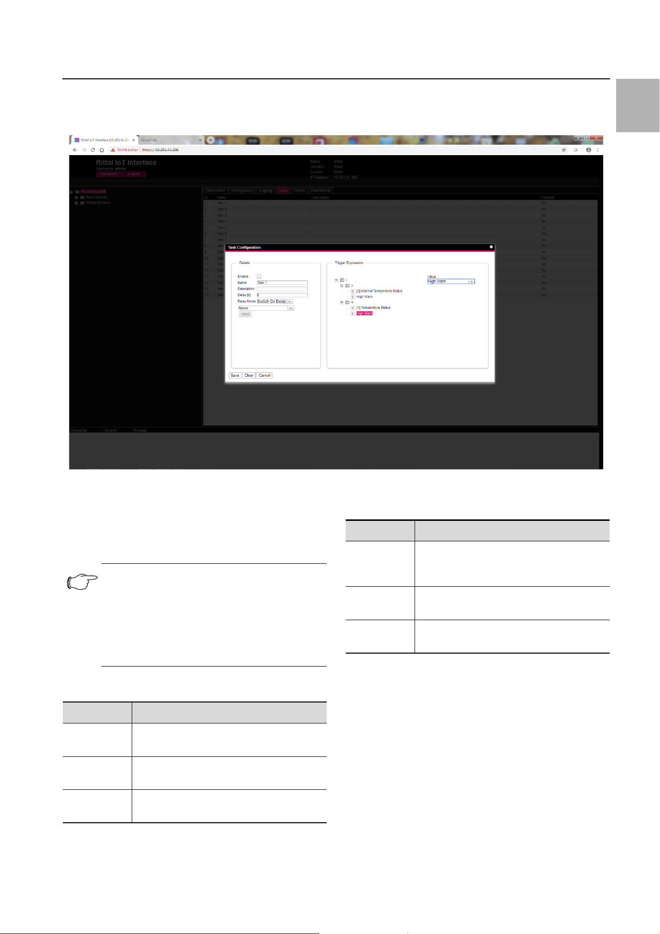
The "Task Configuration" dialogue appears.
Fig. 1: "Task Configuration" dialogue
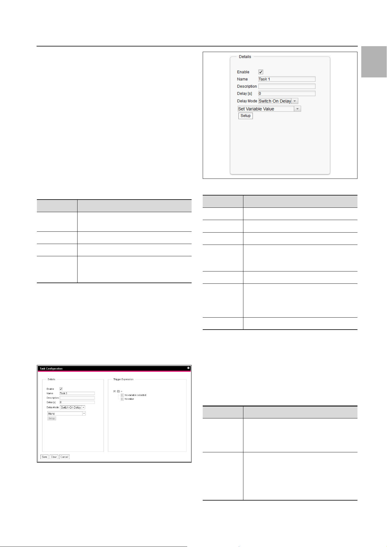
1.3.1 Details group frame
Make the following settings in the left-hand Details
group frame:
Fig. 2: Details group frame
1.3.2 Delaying a task
A task can also be controlled with a delay time. This de-
lay time is specified with the "Delay [s]" parameter and
can be selected as required in the range 0 to 9999sec-
onds.
The delay time is configured using the dropdown list of
the "Delay Mode" parameter:
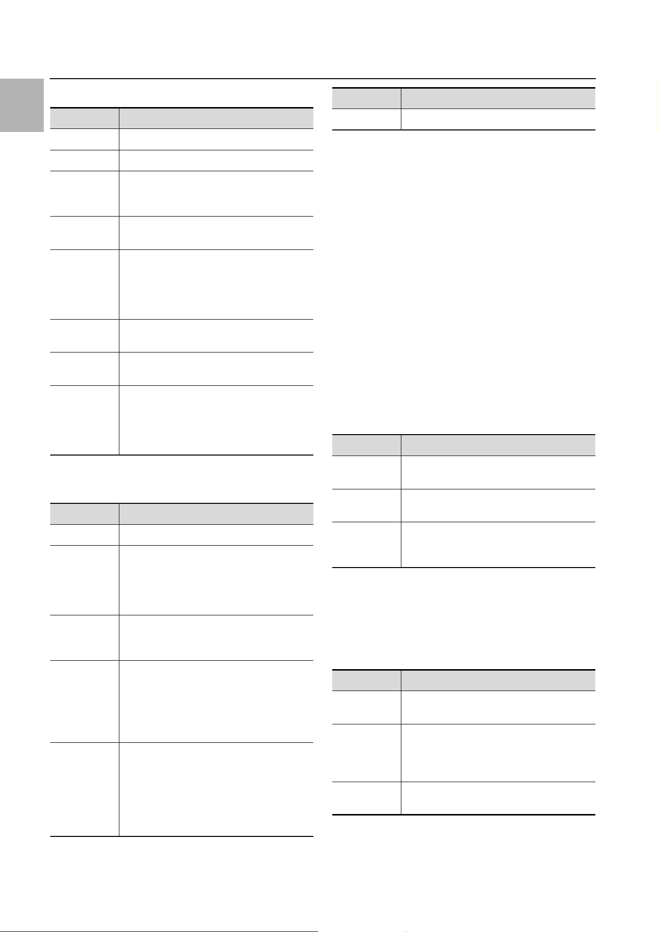
Parameter Explanation
ID Unique ID of the task. This ID is defined by
the system and cannot be changed.
Name Designation of the task.
Description (Detailed) Description of the task.
Enabled Display "Yes" or "No" as to whether the ap-
propriate task is activated, i.e. the associ-
ated action is performed (or not).
Tab. 1: Tasks tab
Parameter Explanation
Enable Activate or deactivate the task.
Name Designation of the task.
Description (Detailed) Description of the task.
Delay Delay time of a task in seconds. If the value
"0" is entered here, no delay occurs irre-
spective of the selected "Delay Mode".
Delay Mode Type of the delay
Dropdown
list
Select an action to be performed when the
associated expression is "true" or "false".
Alternatively, a parameter value can also be
selected.
Setup Definition of the action to be performed.
Tab. 2: Details group frame
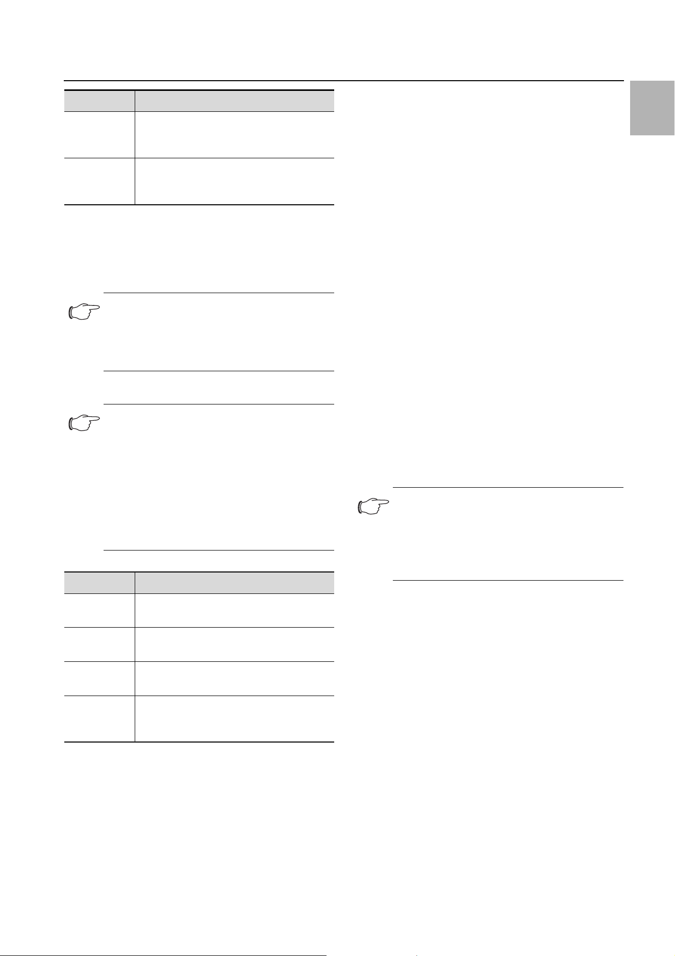
Parameter Explanation
Switch On
Delay
Switch-on delay. If the associated expres-
sion evaluates "true", the system first waits
the defined "delay" time before the set ac-
tion is performed.
Switch Off
Delay
Switch-off delay. If the associated expres-
sion evaluates "true", the set action is per-
formed immediately. If a status changes
and the expression evaluates "false" again,
the system waits the defined "delay" time
before the set action is undone.
Tab. 3: Selection list for the delay of a task
1 Tasks
EN
4 Rittal IoT interface – Tasks and Virtual Devices
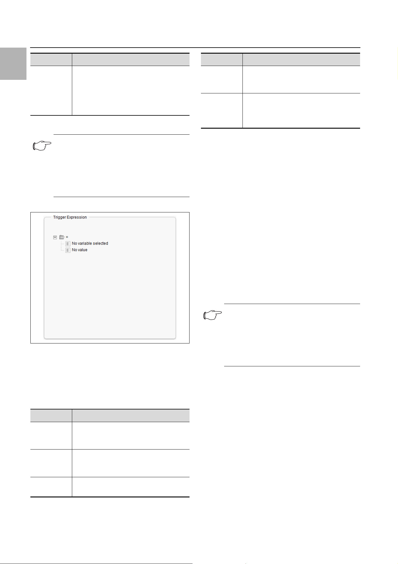
1.3.3 Trigger Expression group frame
Fig. 3: Trigger Expression group frame
Specify in the right-hand Trigger Expression group
frame the expression to be checked. For this purpose,
various variables can be linked with each other using the
Boolean operators "Or" ("|"), "And" ("&"), "Not Or" ("~|"),
"Not And" ("~|"), "Equal to" ("=") and "Not equal to"
("<>").
The dropdown lists for selection of the various setting
options are displayed after clicking the default specified
values "=", "No Variable Selected" or "No Value" (see
section 1.5 "Example for creating a task").
The "=" and "<>" operators can be used to check varia-
bles of the IoT interface itself or the connected devices
for a specific status. Alternatively, time details (weekday)
can also be checked.
The two "|" and "&" operators are used to link subordi-
nate expressions appropriately with each other.
Proceed as follows to create an expression:
If several expressions should be checked: First specify
whether both subordinate expressions must supply
the value "true" (operator "&") or only one value suffic-
es to initiate the action (operator "|").
Specify separately for all subordinate expressions
whether it supplies the value "true" when the variable
or the time specification corresponds to the value (op-
erator "=") or not (operator "<>").
Pulse Pulse. If the associated expression evalu-
ates "true", the system performs the set
action for the duration of the defined "de-
lay" time. After expiration of this time, the
action is stopped and reset to the associ-
ated origin.
Note:
In general, the selected action is performed
only when the "Trigger Expression" is always
true after expiration of the delay time. If, how-
ever, a value changes during the delay time
and the "Trigger Expression" is no longer
true, the selected action is not performed.
Parameter Explanation
Operator
Type
Boolean operator with which the subordi-
nate expressions should be linked or the
variables checked.
Nature Selection of the "Time" used to check a
time value, or "Variable" to check a variable
value.
Device Selection of the device for which a value
should be checked.
Tab. 4: Trigger Expression group frame
Parameter Explanation
Tab. 3: Selection list for the delay of a task
Variable Variable whose value should be checked.
This list displays only those variables made
available for the previously selected device.
Value Status for which the variable should be
checked. This list displays only those sta-
tuses made available for the previously se-
lected variable.
Note:
The following descriptions include short vid-
eo sequences. They are started by clicking
the picture. For a representation in full-screen
mode, after the start, right-click the video and
select the "Full-screen mode for multimedia"
entry.
Parameter Explanation
Tab. 4: Trigger Expression group frame
Rittal IoT interface – Tasks and Virtual Devices 5
1 Tasks
EN
Example: An action is performed when the measured
internal temperature at the Blue e+ cooling unit or on the
IoT interface assumes the "High Warning" status.
Fig. 4: "Trigger Expression" video
1.4 Selection of an action
Finally, assign to the task an action from the dropdown
list when the complete expression switches to the value
"true".
Choose between the following settings:
After selection of the desired action, you must still con-
figure it appropriately.
To do this, click the Setup button.
Depending on the previously selected action, enter in
the appropriate dialogue to which, for example, a status
e-mail will be sent ("Send Status Email" action), for which
status an alarm message should be suppressed ("Sup-
press Alarm Message" action), etc.
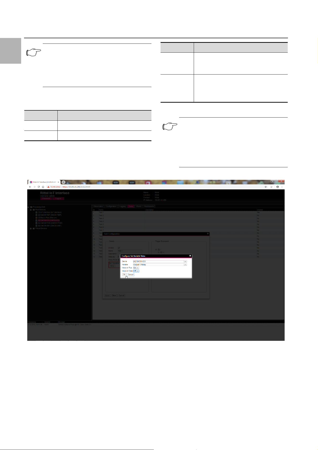
1.4.1 "Set Variable Value" action
For selection of the "Set Variable Value" action, "switch-
able" variables (such as the digital outputs of a connect-
ed IO unit) can be set. Alternatively, you may opt for no
action ("Do nothing": Select "--").
Note:
The action stored for a task is always per-
formed only after a status change. If the defi-
nition of a task is changed, e.g. the logic of a
switching output, the output is not switched
directly when the change is accepted, but
only when the status of an input changes.
Parameter Explanation
Send Status
Email
Send a status e-mail.
Suppress
Alarm Email
Suppress the sending of the e-mail to the
selected recipients.
Suppress
Alarm Trap
Suppress the sending of the trap to the se-
lected recipients.
Tab. 5: Details group frame
Suppress
Alarm Mes-
sage
Suppress the alarm message of the select-
ed status variable.
Set Variable
Value
Set a variable value.
Shutdown
Server
Orderly shutdown of a server.
Parameter Explanation
Tab. 5: Details group frame
1 Tasks
EN
6 Rittal IoT interface – Tasks and Virtual Devices
After clicking the Setup button, the "Configure Set Var-
iable Value" dialogue appears.
Fig. 5: "Set variable value" video
1.4.2 Grouping of outputs
The assignment of an output to a group makes it possi-
ble with a single task or switching command via the
website, Telnet or SNMP to switch several outputs (also
different components) in the same manner. This avoids
the need to create a separate appropriate task for each
of these outputs.
If you have assigned several outputs the same group
number, the selection of one of these outputs also
switches all other outputs of this group correspondingly.
1.4.3 "Shutdown Server" action
If the "Shutdown Server" action is selected, servers on
which an appropriate licence of the RCCMD software is
installed can be shutdown orderly (see section 8.5.8
"Server Shutdown Configuration" in the assembly and
operating instructions).
Note:
In the "Config Set Variable Value" dialogue,
you must select in the "Device" dropdown list
a device with a switchable variable so that the
associated selection options are displayed in
the fields below.
Parameter Explanation
Device Device on which the variable should be set.
Variable Variable that should be set.
Tab. 6: "Configure Set Variable Value" dialogue
Value on
True
The value of the variable when the expres-
sion specified previously in the Trigger Ex-
pression group frame has the value "true".
Value on
False
The value of the variable when the expres-
sion specified previously in the Trigger Ex-
pression group frame has the value
"false".
Note:
Ensure that different values are selected in
the two "Value on True" and "Value on False"
dropdown lists. Otherwise, the variable re-
tains this value even when the value of the ex-
pression in the Trigger Expression group
frame changes.
Parameter Explanation
Tab. 6: "Configure Set Variable Value" dialogue
Rittal IoT interface – Tasks and Virtual Devices 7
1 Tasks
EN
After clicking the Setup button, the "Shutdown Server"
dialogue appears.
Activate in the "Use" column the servers to be shut-
down when the expression specified previously in the
Trigger Expression group frame has the value
"true".
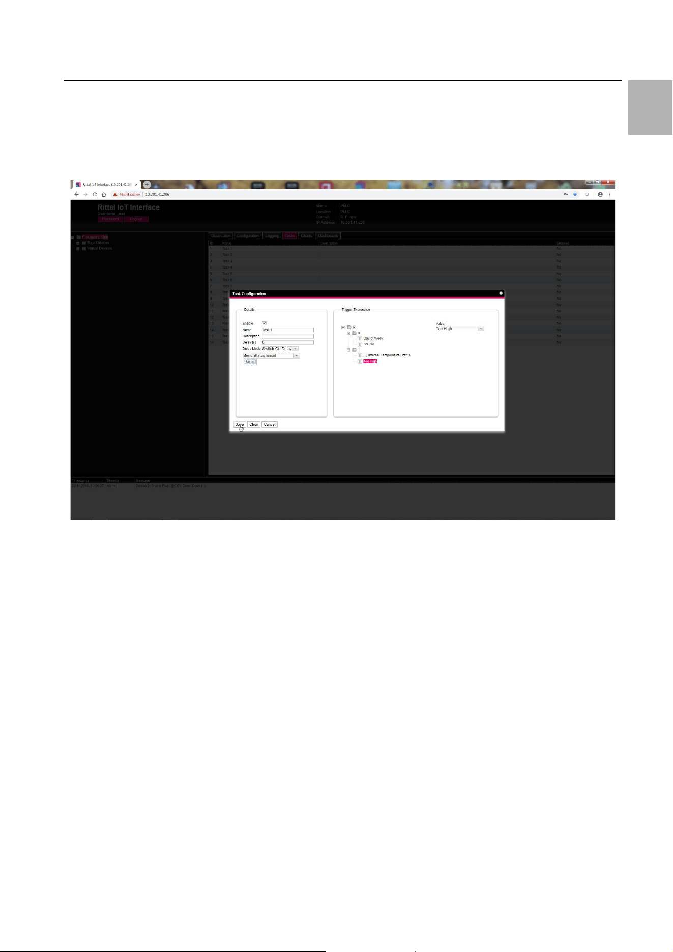
1.5 Example for creating a task
You want to define a task that sends a status e-mail
when the enclosure internal temperature exceeds the
alarm threshold at the weekend.
Fig. 6: "Creating a task" video
1.6 Deactivating or deleting a task
Tasks that are not required can be deactivated or delet-
ed.
Open the configuration menu of the associated task.
1.6.1 Deactivating a task
Deactivate the "Enable" checkbox.
Click the Save button to save the configuration.
1.6.2 Deleting a task
Click the Clear button.
This causes the task settings to be reset to their de-
fault values.
Click the Save button to save the configuration.

2 Virtual Devices
EN
8 Rittal IoT interface – Tasks and Virtual Devices
2Virtual Devices
2.1 General
The so-called "Virtual Devices" are displayed below the
"Real Devices" in the left-hand area of the screen,
i.e. the devices actually connected to the IoT interface.
They must first have been created on the right-hand side
by clicking the Configuration tab.
Sensors and output devices can be coupled to form a
new, predefined type of "virtual device". For example,
when a specified temperature measured with a temper-
ature sensor connected or the Blue e+ cooling unit is
overshot, a fan connected to a Power Unit
(DK 7030.050) will be switched on.
A virtual device is treated as a dedicated component, for
which, for example, the status can also be queried via
SNMP. Although such a status query is not possible for
a task, tasks can be configured to a greater extent.
2.2 Types of virtual devices
You can select the following types as virtual device:
– Two-Level Controller
– Access Controller
– Blue e+ Remote Controller
2.2.1 Two-Level Controller
Such a controller can be used to switch an output on or
off (e.g. an output of a connected IO unit) using a spec-
ified (threshold) value (e.g a limit temperature). The
above-mentioned (threshold) value is specified directly in
the virtual device and is independent of the limit values
defined in the actual sensor.
In contrast to a task, a two-level controller cannot eval-
uate the status of the assigned sensor. This possible
only with a task (see section 1 "Tasks") for which com-
binations of status and time conditions can be set and
one or more actions performed.
2.2.2 Access Controller
An access controller can be used to switch a switchable
output using a reader (transponder reader or number-
combination lock). This allows, for example, a room ac-
cess door to be monitored and opened.
2.2.3 Blue e+ Remote Controller
The remote controller allows a Blue e+ cooling unit to be
passed different values as input factors. The input fac-
tors can be sent to the Blue e+ cooling unit either via
sensors also connected to the IoT interface or via an ex-
ternal controller (PLC).
2.3 Creating a virtual device
You create a virtual device on the Configuration tab. To
do this:
Select the "Virtual Devices" entry in the navigation area
of the screen.
Click the Configuration tab in the right-hand area of
the screen.
Click the New button in the List of Virtual Devices
group frame.
Select the desired type of the virtual device in the "Vir-
tual Device Type" dropdown list in the "Create new Vir-
tual Device" dialogue (e.g. "Two-Level Controller").
Click the OK button to confirm the selection.
The configuration change causes the list of all devices
to be reloaded automatically. A new component, e.g.
the above-mentioned "Two-Level Controller", marked
with a small green "+" character appears in the navi-
gation area under the "Virtual Devices". The multi-LED
of the IoT interface flashes cyclically green – orange –
red.
Confirm the message for the configuration change
(see section 6.4 "Acknowledgement of messages" in
the assembly and operating instructions).
The device list is reloaded automatically. The entry un-
der the "Virtual Devices" now has a yellow background
and the LED of the IoT interface illuminates orange
continuously provided no other alarm is pending.
Then specify the input and output of the virtual device.
Depending on the virtual device type, the output of the
virtual device can only be specified (see section 2.4
"Inputs and Outputs").
The device list is then reloaded automatically. A blue
"information" symbol is displayed in the entry under
the "Virtual Devices" and the LED of the IoT interface
illuminates green continuously provided no other
alarm is pending.
Then configure all settings on the Observation tab
(see section 2.5 "Configuring a virtual device").
2.4 Inputs and Outputs
If a "Virtual Device" is selected in the navigation area, an
additional "Configure Inputs and Outputs" icon appears
on the Configuration tab. In addition to the configura-
tion of the access rights and the behaviour on occur-
rence of an alarm, the inputs and outputs must also be
configured for a virtual device.
Select the desired "Virtual Device" in the navigation ar-
ea.
Click the Configuration tab in the right-hand area of
the screen.
Click the "Configure Inputs and Outputs" icon.
Alternatively, click the Edit button in the list of all virtual
devices.
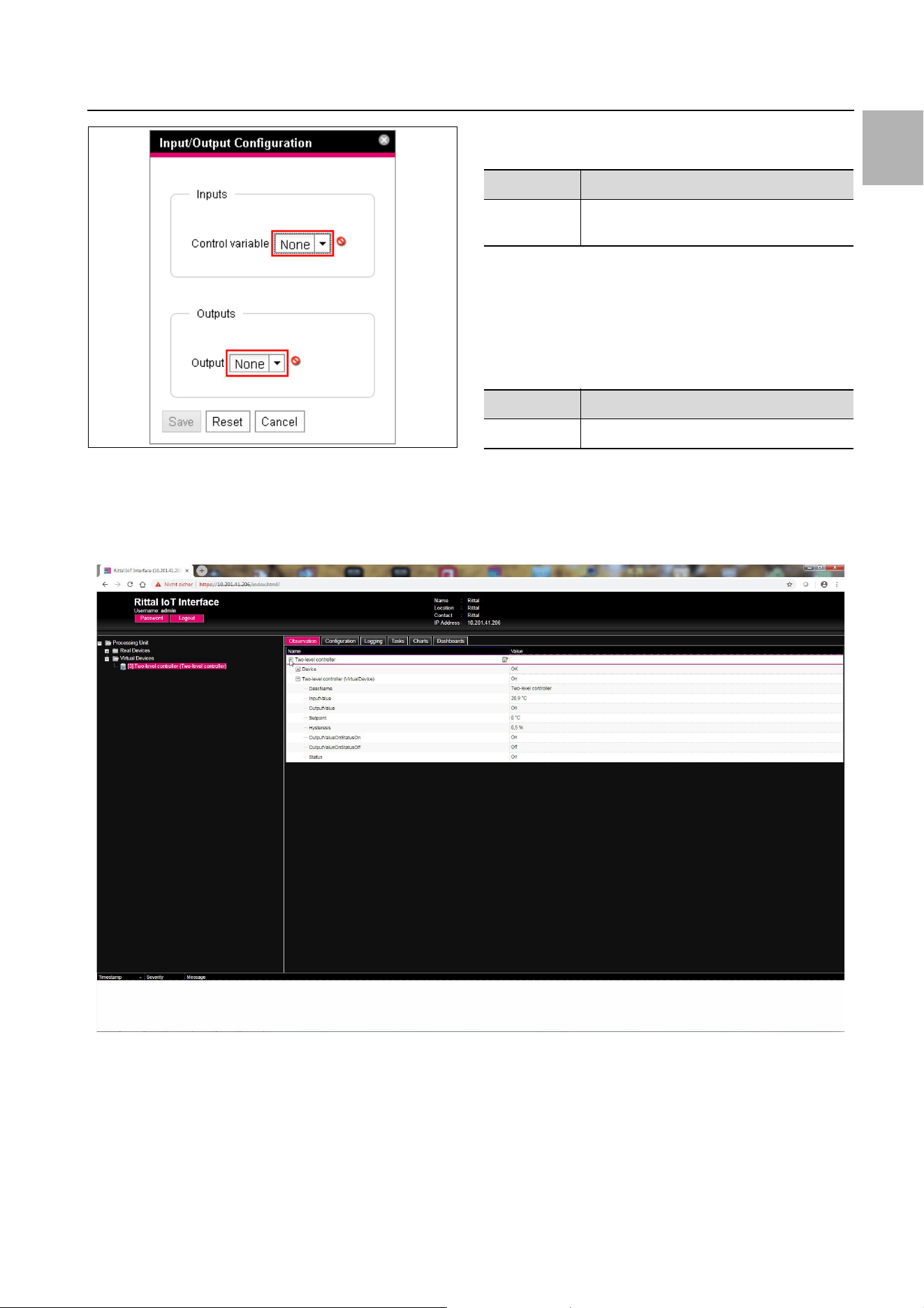
The "Input/Output Configuration" dialogue appears.
Note:
Only one remote controller may be created
for each cooling unit. Otherwise, conflicts can
occur in the closed-loop control and so
cause undefined states.
Rittal IoT interface – Tasks and Virtual Devices 9
2 Virtual Devices
EN
Fig. 7: "Input/Output Configuration" dialogue
For a virtual device of the type "Two-level controller":
Select the desired variable in the "Control Variable"
dropdown list, e.g. "Blue e Plus.Internal Tempera-
ture.Value" for the currently measured temperature
value of the air drawn from the enclosure into the cool-
ing unit.
The Inputs group frame does not exist for a virtual de-
vice of the "Access Controller" type.
Select in the "Output" dropdown list the output that for
a specified change of the variable value defined above
should be switched.
The device list is then reloaded automatically and you
can further configure the virtual device.
Fig. 8: "Creating a virtual device" video
2.5 Configuring a virtual device
Select the appropriate "Virtual Devices" in the naviga-
tion area of the screen.
Click the Observation tab to perform the settings.
On the "Device" level, general settings for the virtual de-
vice are performed or parameters displayed that provide
detailed information about the virtual device (see
section 8.3.1 "Device" in the assembly and operating in-
structions). The "Production Date" parameter shows the
calendar week in which the Virtual Device was created in
the IoT interface. This requires that the system time in
the IoT interface was set correctly.
Depending on the virtual device type, various parame-
ters are displayed on the "Virtual Device" level.
Parameter Explanation
Control Vari-
able
Variable whose value should be monitored.
Tab. 7: Inputs group frame
Parameter Explanation
Output Output to be switched.
Tab. 8: Outputs group frame
2 Virtual Devices
EN
10 Rittal IoT interface – Tasks and Virtual Devices
2.5.1 Two-Level Controller
2.5.2 Access Controller
Ensure that the configuration of an access controller has
the following sequence:
Select the status in the "AccessLogic" dropdown list
into which the access controller should switch,
e.g. "Delayed Off".
Create with the "Delay" parameter the duration with
which the output is switched into the previously select-
ed status.
Activate the "Switch" entry in the "Value" dropdown
list.
The access controller switches for the entered dura-
tion into the previously selected status, e.g. "Off", and
then into the other status, e.g. "On".
Specify in the access configuration with which access
codes or which transponder cards the access control-
ler can be activated (see section 8.7.3 "Access Con-
figuration" in the assembly and operating instructions).
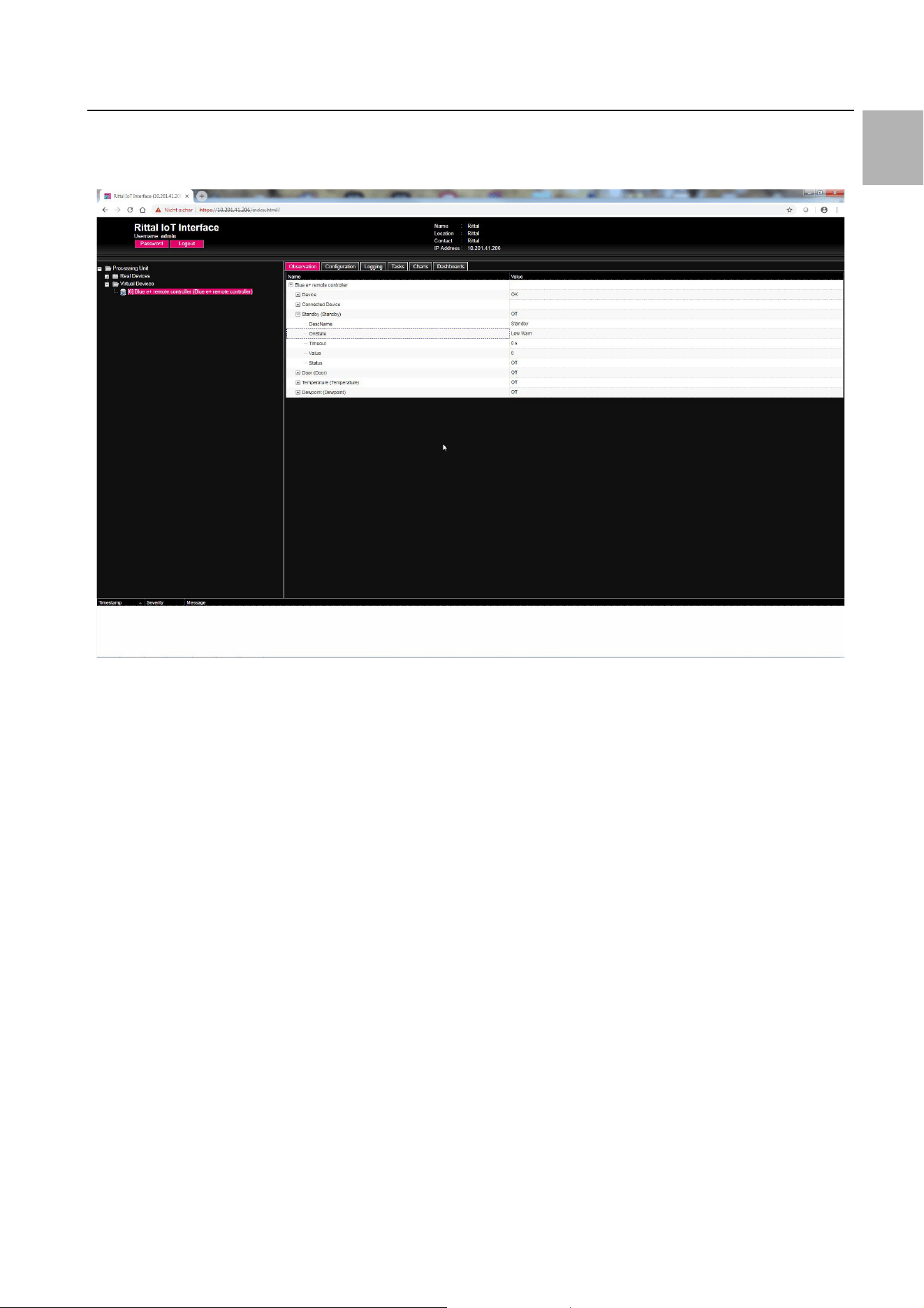
2.5.3 Blue e+ remote controller
Connected Device
Standby and Door
The "Standby" and "Door" functions both place the con-
nected cooling unit into standby mode. The "Door" func-
tion also issues the "Door open" message on the cooling
unit display.
Parameter Explanation
DescName Individual description of the virtual device.
InputValue Current value of the virtual-device input.
OutputValue Current value of the output taking account
of the settings for "OutputValueOnStatus-
On" or "OutputValueOnStatusOff".
Setpoint Switching point of the input for a status
change of the output.
Hysteresis Required percentage deviation for under-
shooting or overshooting the switching
point for a status change (see section 16
"Glossary" in the assembly and operating
instructions).
OutputValue
OnStatusOn
Value of the output when the input value
lies above the switching point ("On" status).
OutputValue
OnStatusOff
Value of the output when the input value
lies below the switching point ("Off" status).
Status Current status of the two-level controller.
Status "On": Input value lies above the
switching point.
Status "Off": Input value lies below the
switching point.
Tab. 9: "VirtualDevice" level for a two-level controller
Parameter Explanation
DescName Individual description of the virtual device.
Command The selection of the "Switch" command
switches the output of the virtual device. It
then switches for the duration stored in the
"Delay" field the status stored in the "Ac-
cessLogic" field.
OutputValue The current value of the switchable output
that has been assigned to the access con-
troller ("On" or "Off").
Delay Duration for which the output of the virtual
device changes its status. After expiration
of this time, the output switches back to its
original status. This parameter acts only
when the "Toggle Output" entry is not se-
lected in the "AccessLogic" dropdown list.
Access
Logic
Status to which the output of the virtual de-
vice switches for permitted access.
"Delayed On": Activate the output.
"Delayed Off": Deactivate the output.
"Toggle Output": Switch the output to the
other status (from "On" to "Off" and vice
versa).
Tab. 10: "VirtualDevice" level for an access controller
Status Current status of the access controller.
Parameter Explanation
Serial Num-
ber
Serial number of the connected device.
Type Type of the connected device. Only the
Blue e+ cooling unit is currently supported.
Interface The designation of the interface to which
the device is connected (Modbus 1 or
Modbus 2).
Tab. 11: "Connected Device" level
Parameter Explanation
DescName The individual description of the associated
"Standby" or "Door" function.
OnState The status for which the cooling unit is
placed in the "Standby" or "Door" mode.
The status that can be selected here de-
pends on the input linked with this function.
TimeOut The time until the external closed-loop con-
trol is deactivated.
Tab. 12: "Door" or "Standby" level
Parameter Explanation
Tab. 10: "VirtualDevice" level for an access controller
Rittal IoT interface – Tasks and Virtual Devices 11
2 Virtual Devices
EN
When creating the link, the current status of a sensor is
used as "OnState". The value of the "OnState" parame-
ter can be selected subsequently from the states availa-
ble for selection.
Temperature and Dewpoint
If two Blue e+ cooling units are connected to an IoT in-
terface, these two devices can be controlled in accord-
ance with the temperature value of a connected CMC III
temperature sensor.
To use the "Dewpoint" function, a humidity sensor
(7030.111) must be connected to the IoT interface. The
current dewpoint is determined from the "Temperature"
and "Humidity" measured values used as input for this
function. If the dewpoint temperature exceeds the ex-
pected evaporation temperature, the integrated con-
densate evaporation is deactivated to save energy.
The Blue e+ cooling unit can be controlled via an exter-
nal controller (PLC). In this case, for example, an appro-
priate value can be transferred via SNMP, OPC UA or
ModBus/TCP from the PLC to the IoT interface in order
to place the Blue e+ cooling unit into standby. In such a
case, observe the following comments for the variables.
– The "TimeOut" and "Value" variables are read-only.
– Although the value of the "TimeOut" variable is set au-
tomatically by the remote controller, it cannot be
viewed in the web user interface for operating the de-
vice or via SNMP. The value is copied directly to the
Blue e+ cooling unit.
– The external closed-loop control is active immediately
once the sensor is connected with the IoT interface
and has been configured appropriately.
For the "Status" variable, the following values are possi-
ble for closed-loop control via connected sensors:
– N/A: Initialisation of the remote controller.
– On: The remote controller sends data.
– Off: The remote controller does not send any data.
– Changed: The remote controller does not receive any
valid input value (e.g. the sensor is disconnected).
Closed-loop control via external controller
The Blue e+ cooling unit can be controlled externally via
an external controller. In this case, for example, the val-
ues of external sensors are acquired by the software and
transferred via SNMP to the IoT interface in the appro-
priate fields. In such a case, observe the following com-
ments for the variables.
– The "TimeOut" and "Value" variables must be filled
with values by the external controller.
– The value of the "TimeOut" variable must be set again
cyclically by the external controller before it is decre-
mented to the value "0".
– The value of the "Value" variable must also be set by
the external controller.
– The external closed-loop control is active while the val-
ue of the "TimeOut" variable is larger than "0".
– If the "TimeOut" variable has the value "0" for a stored
time, the cooling unit switches automatically to auto-
nomous closed-loop control. This ensures a cooling
function even for failure of the external control.
Value The current value of the remote controller.
Value "0": remote controller is inactive.
Value "1": remote controller is active.
Status The current status depending on the se-
lected closed-loop control variant of the re-
mote controller.
Note:
Because the current status of the sensor is
used as "OnState", the connected cooling
unit always switches initially to standby
mode when the link is created.
Note:
To allow the closed-loop control to be made
in accordance with an external temperature
sensor, "external sensor" closed-loop mode
must be selected in the cooling unit. The dis-
played temperature value then also appears
at the "External Temperature" level for the
cooling unit (see section 10.6 "External Tem-
perature" in the assembly and operating in-
structions).
Parameter Explanation
DescName The individual description of the associated
"Temperature" or "Dewpoint" function.
TimeOut The time until the external closed-loop con-
trol is deactivated.
Value The current value of the linked temperature
or dewpoint.
Status The current status depending on the se-
lected closed-loop control variant of the re-
mote controller.
Tab. 13: "Temperature" or "Dewpoint" level
Parameter Explanation
Tab. 12: "Door" or "Standby" level
Note:
– The "Standby" and "Door" items are active
only when the configured "OnState" status
has the value "true".
– The "Temperature" and "Dewpoint" items
are active immediately.

2 Virtual Devices
EN
12 Rittal IoT interface – Tasks and Virtual Devices
For the "Status" variable, the following values are possi-
ble for closed-loop control via connected sensors:
– N/A: Initialisation of the remote controller.
– Remote: The value of the "TimeOut" variable is larger
than "0".
– Off: The value of the "TimeOut" variable is "0".
Linking devices
To create a virtual device of the "Blue e+ remote control-
ler" type, proceed as follows:
Select the "Blue e+ remote controller" entry in the list
of virtual devices.
The "Input/Output Configuration" dialogue opens.
Select either a connected sensor or the "None" input
in the "Inputs" area for the desired "Standby", "Door",
"Temperature" and "Dewpoint" inputs.
The states of all available variables can be selected for
the "Standby" and "Door" inputs; the values of all avail-
able variables can be selected for the "Temperature"
and "Dewpoint" inputs.
For the selection of a sensor (or status value of a sen-
sor), the closed-loop control is activated automatically
via this sensor so that an external software cannot fill
the "TimeOut" and "Value" variables for this input.
Select in the "Devices" area the cooling unit that
should be controlled via the external closed-loop con-
trol.
Note:
The external closed-loop control via an exter-
nal controller is automatically active when no
connected sensor was selected for the ap-
propriate input.
Rittal IoT interface – Tasks and Virtual Devices 13
2 Virtual Devices
EN
Example: Create a Blue e+ controller and the switching
to standby when the internal temperature falls below
20 °C.
Fig. 9: "Connecting a Blue e+ controller" video
2.6 Deleting a virtual device
A virtual device is deleted on the Configuration tab. To
do this:
Select the "Virtual Devices" entry in the navigation area
of the screen.
Click the Configuration tab in the right-hand area of
the screen.
Select in the List of Virtual Devices group frame the
virtual device to be deleted.
Select with pressed "Ctrl" key other virtual devices that
you also want to delete.
Click the Delete button.
A prompt appears as to whether the virtual device
should actually be deleted.
Confirm this by clicking the OK button or terminate the
action by clicking the Cancel tab.
Then confirm the message for the configuration
change (see section 6.4 "Acknowledgement of mes-
sages" in the assembly and operating instructions).

Notes
EN
14 Rittal IoT interface – Tasks and Virtual Devices

Rittal IoT interface – Tasks and Virtual Devices 15
Notes
EN
◾Enclosures
◾ Power Distribution
◾ Climate Control
◾ IT Infrastructure
◾ Software & Services
You can find the contact details of all
Rittal companies throughout the world here.
www.rittal.com/contact
RITTAL GmbH & Co. KG
Postfach 1662 · D-35726 Herborn
Phone +49(0)2772 505-0 · Fax +49(0)2772 505-2319
E-mail: [email protected] · www.rittal.com
01.2019 / Document no. D-0000-00001873-00
