
THIS INSTRUCTION BOOKLET CONTAINS IMPORTANT SAFETY INFORMATION. PLEASE READ AND KEEP FOR FUTURE REFERENCE.
USER’S MANUAL
EN DE FR IT PL
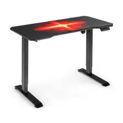
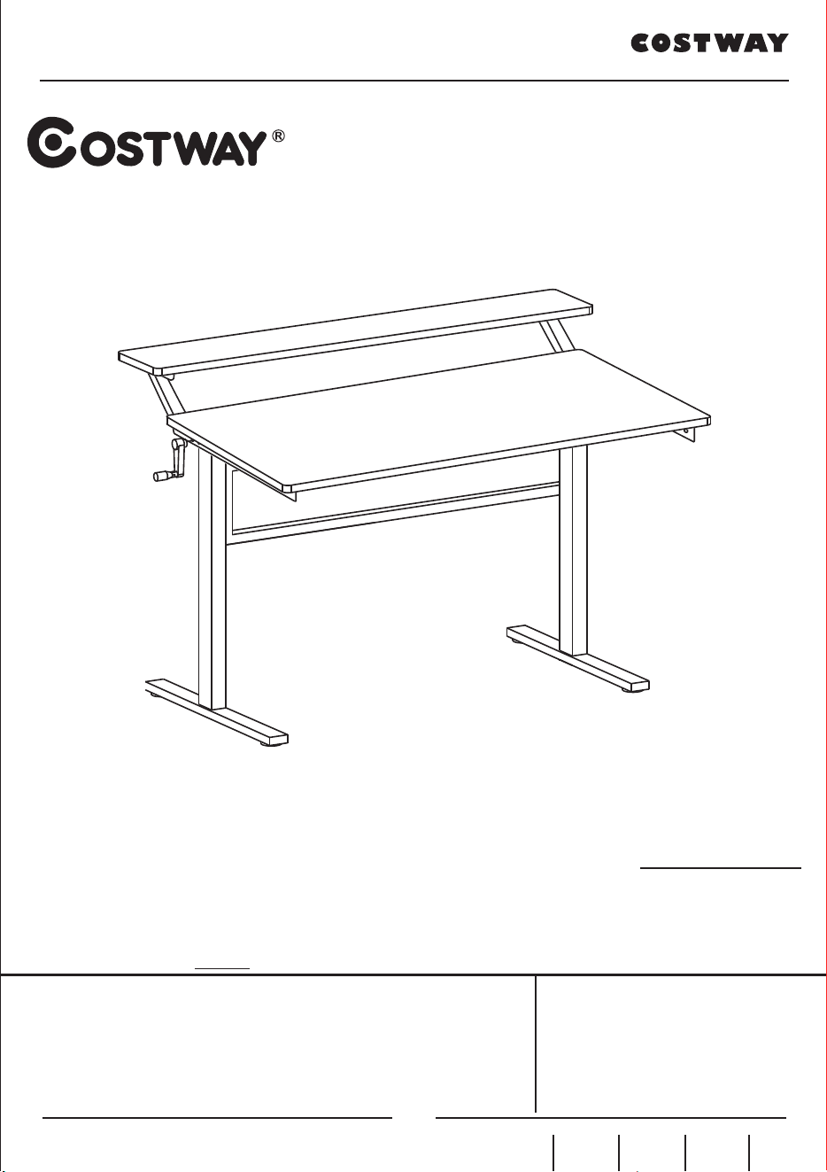
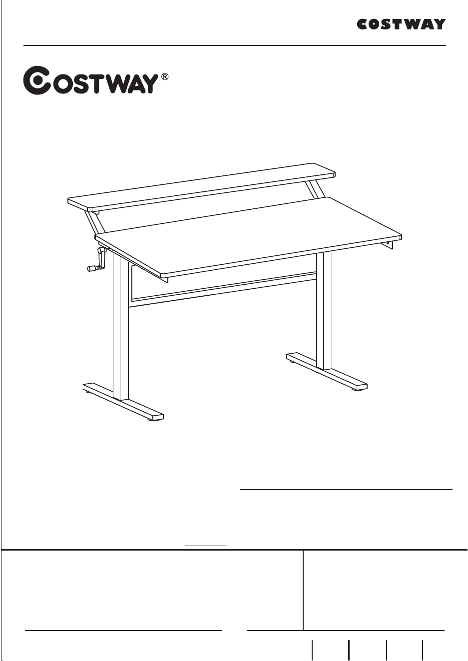
Crank Adjustable Standing Desk
HW65656

THIS INSTRUCTION BOOKLET CONTAINS IMPORTANT SAFETY INFORMATION. PLEASE READ AND KEEP FOR FUTURE REFERENCE.
USER’S MANUAL
EN DE FR IT PL
Crank Adjustable Standing Desk
HW65656

DEAR CUSTOMER
Thank you for choosing our products, please read this manual carefully before
assembling the products to avoid damage caused by improper use.
We are highly appreciated if you could leave feedback when satisfied with our
products and service. Or please contact us any time if any assistance needed. We
will surely solve the problem at full stretch :)
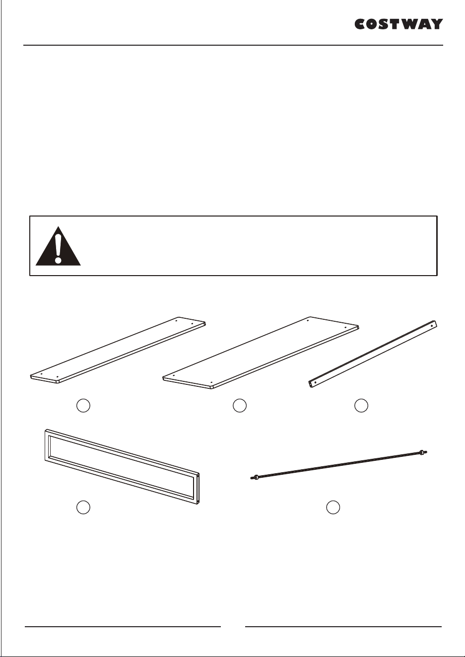
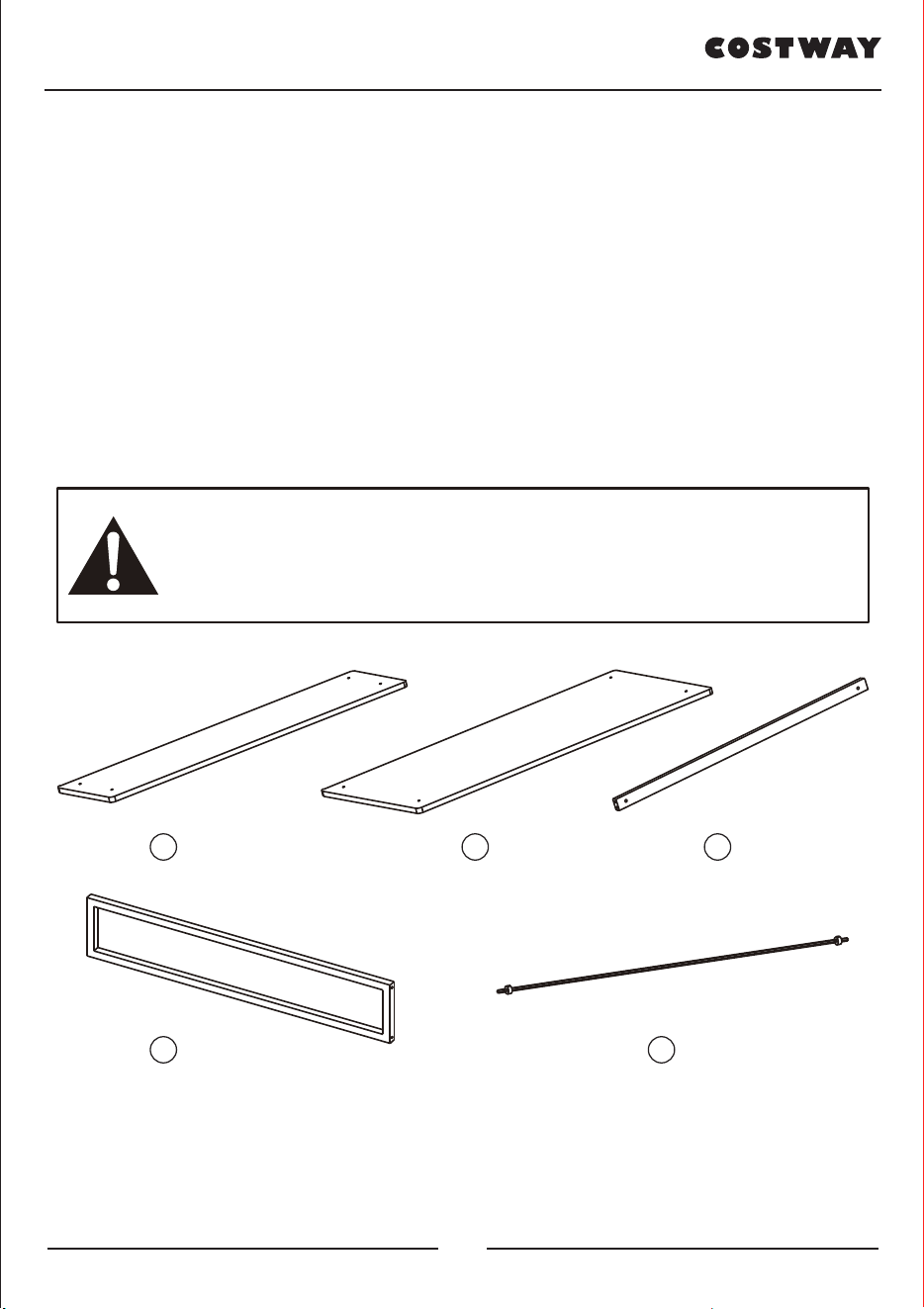
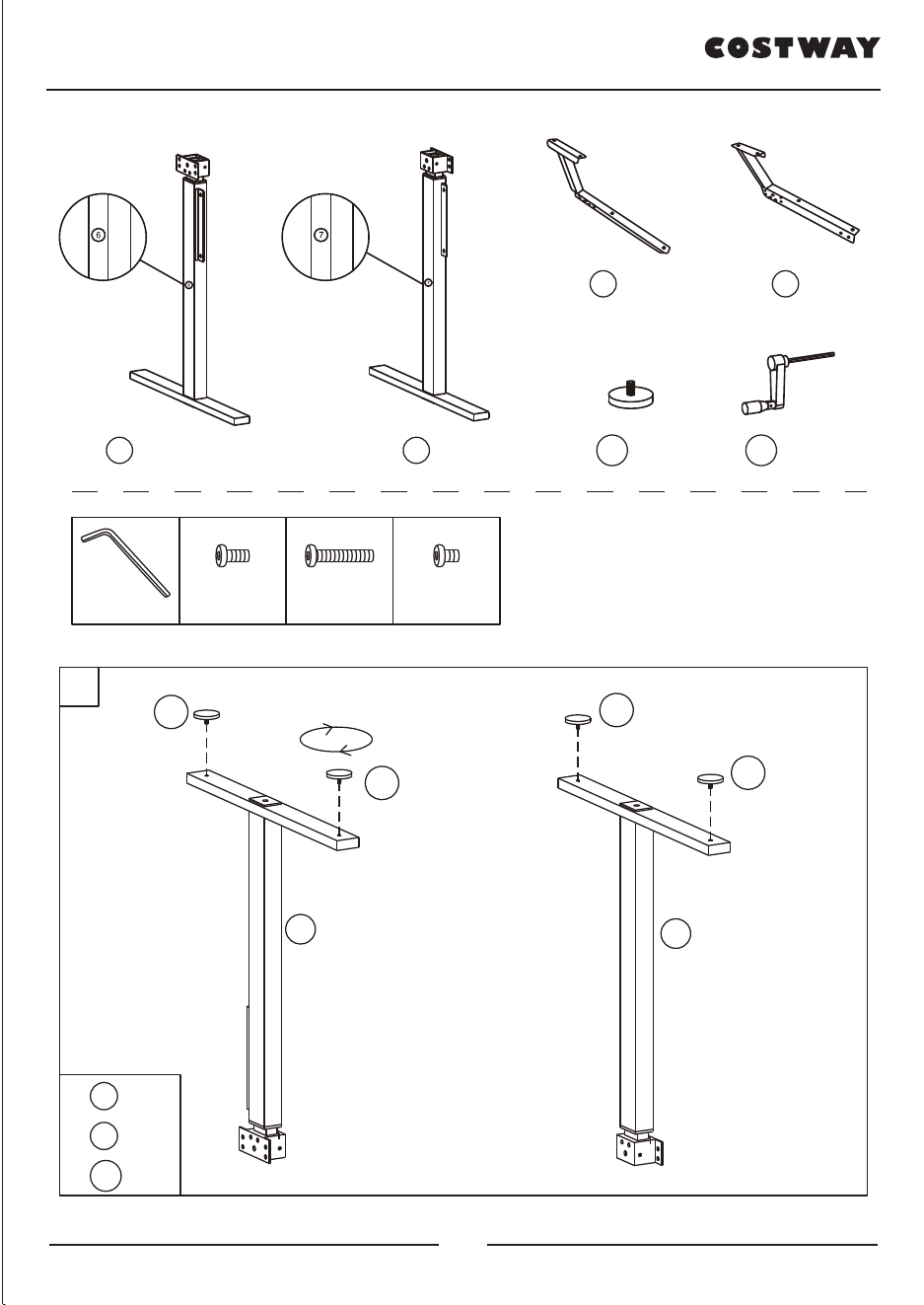
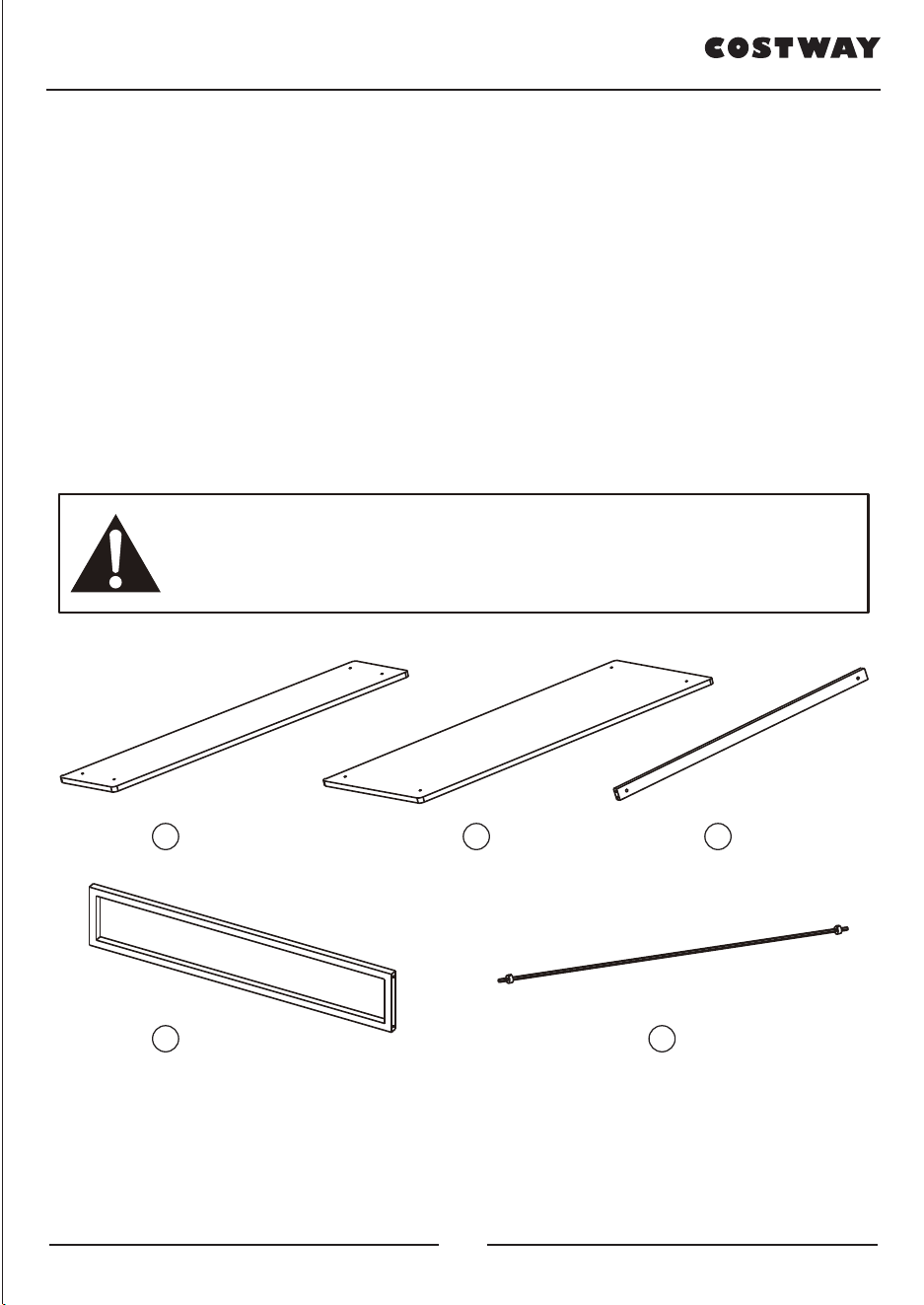
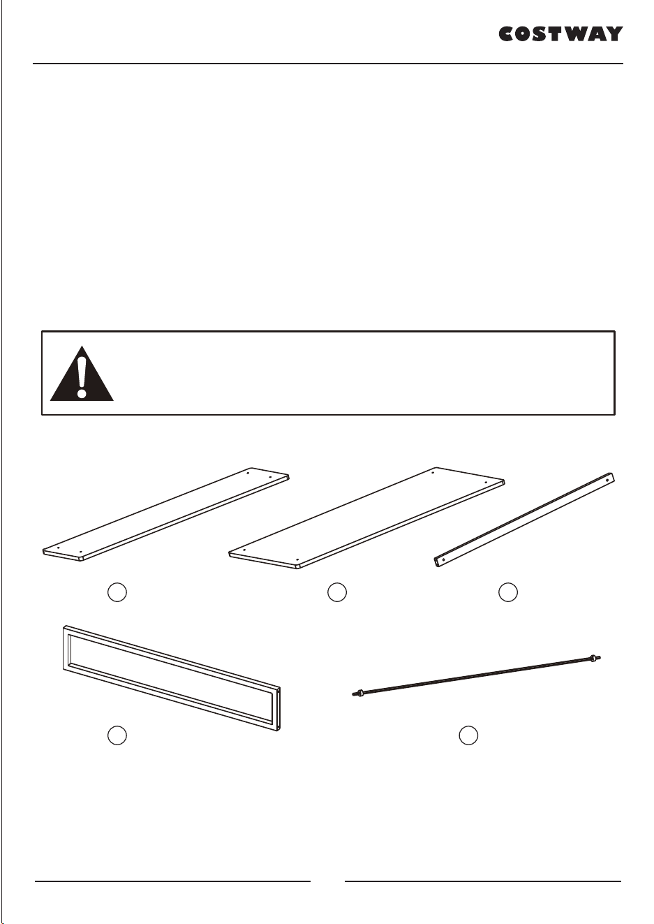
PARTS LIST:
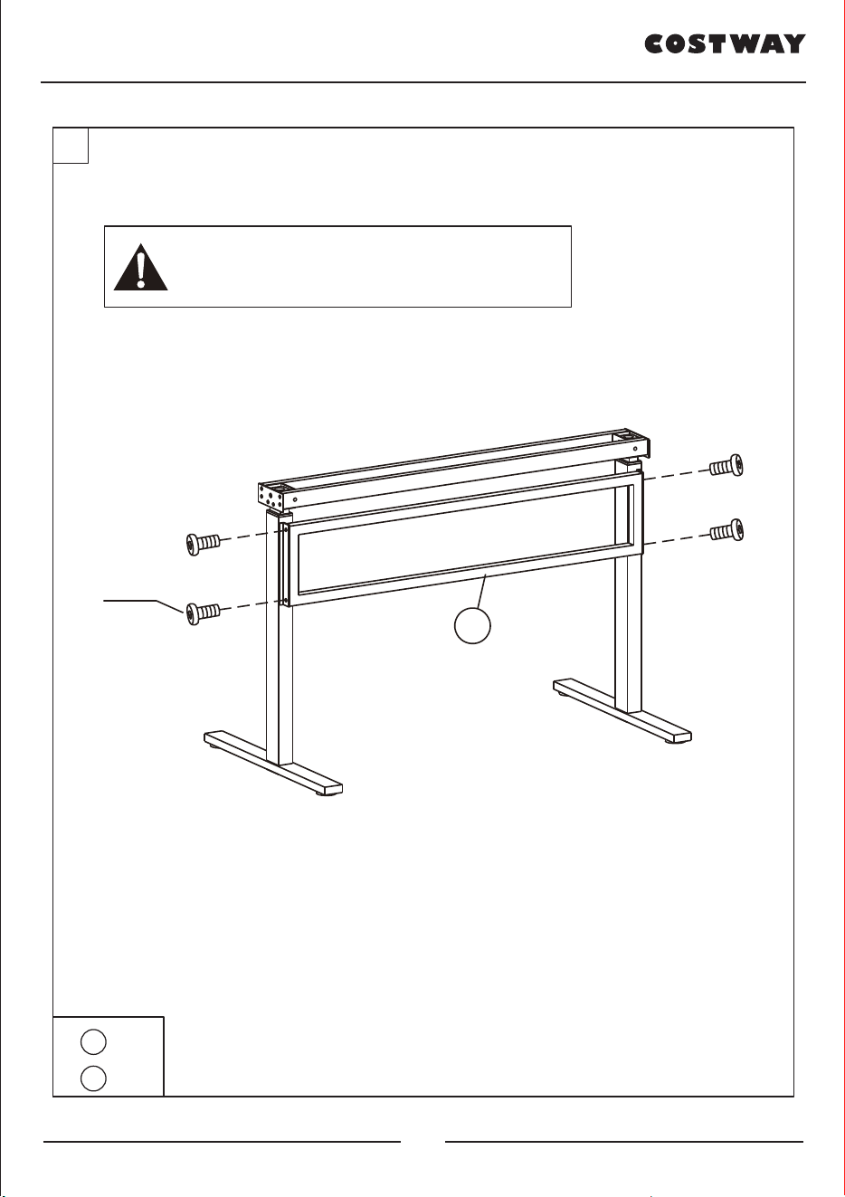
Do not over tighten the screws too much until they are fully
assembled to avoid misalignment of the screw holes.
1 x 1
4 x 1 5 x 1
2 x 1 3 x 2
02 03
DEAR CUSTOMER
Thank you for choosing our products, please read this manual carefully before
assembling the products to avoid damage caused by improper use.
We are highly appreciated if you could leave feedback when satisfied with our
products and service. Or please contact us any time if any assistance needed. We
will surely solve the problem at full stretch :)
PARTS LIST:
Do not over tighten the screws too much until they are fully
assembled to avoid misalignment of the screw holes.
1 x 1
4 x 1 5 x 1
2 x 1 3 x 2
02 03
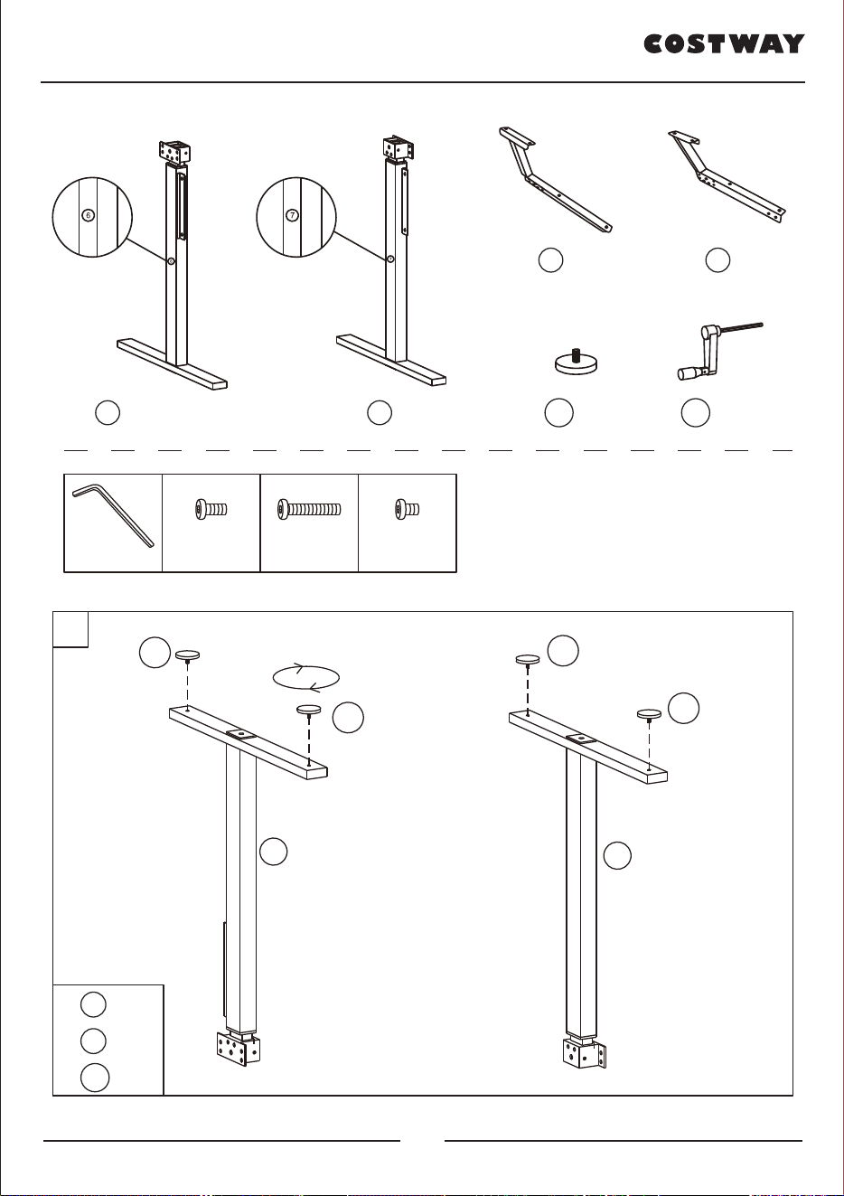
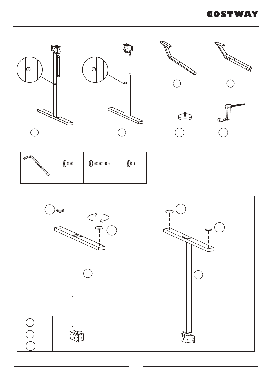
2
3
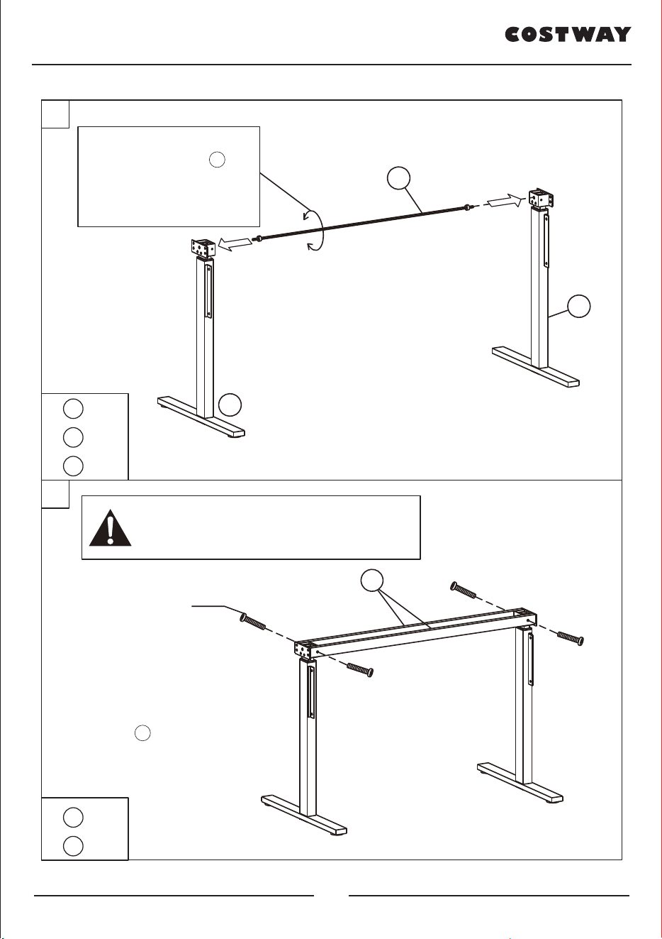
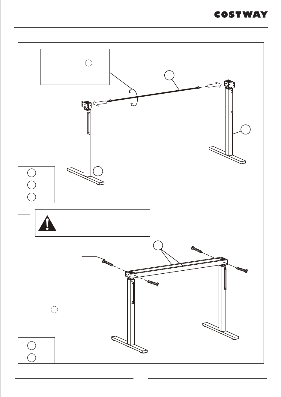
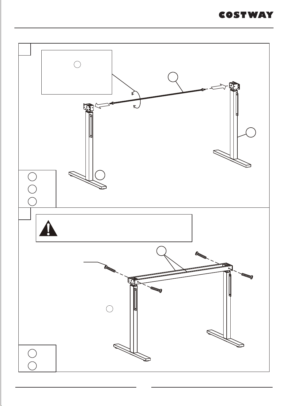
Rotate the haxagonal bar
(Part 5 ) if it can’t insert
into the hole smoothly.
5
7
6
5 x1
6 x1
7 x1
3 x2
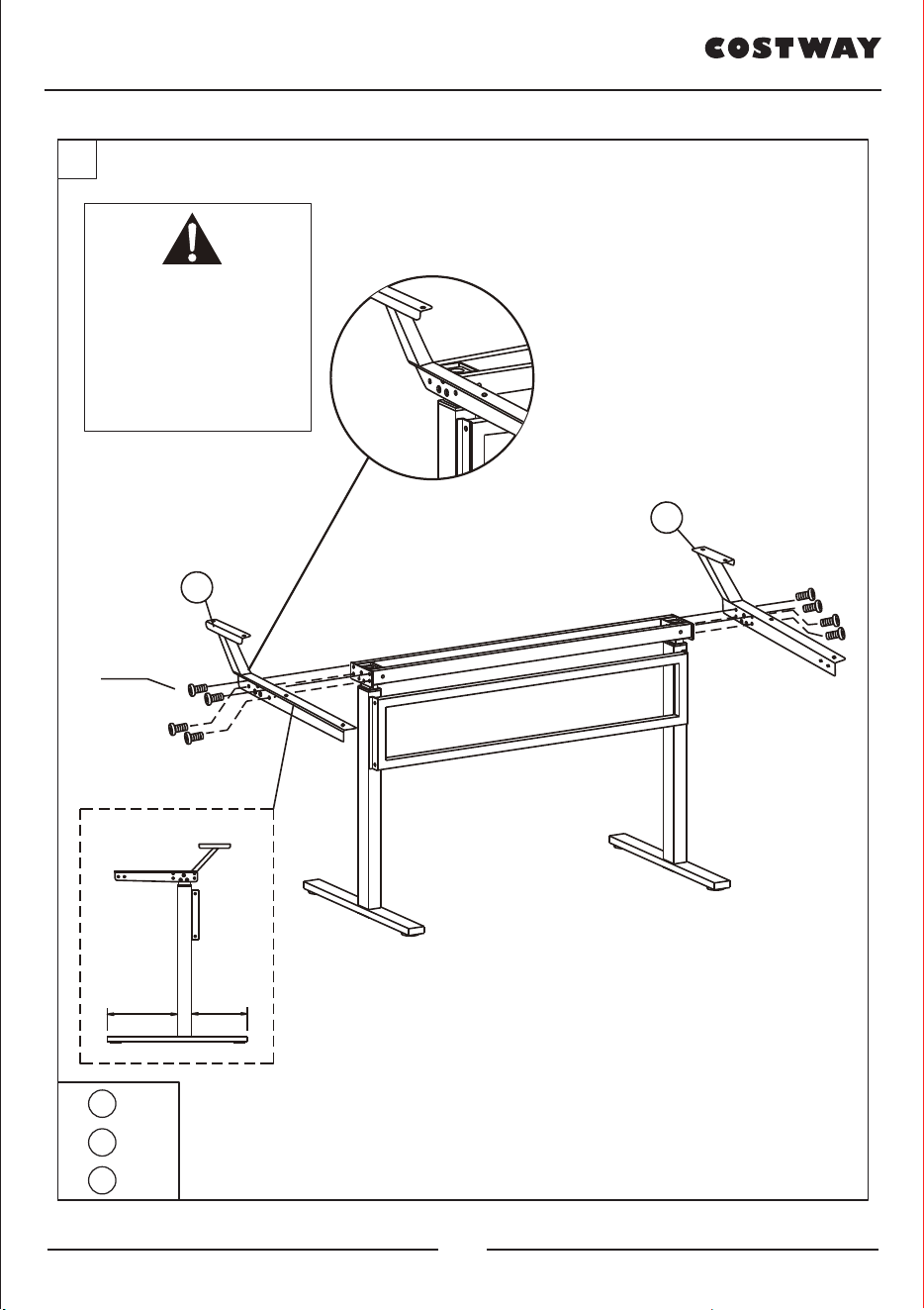
C x4
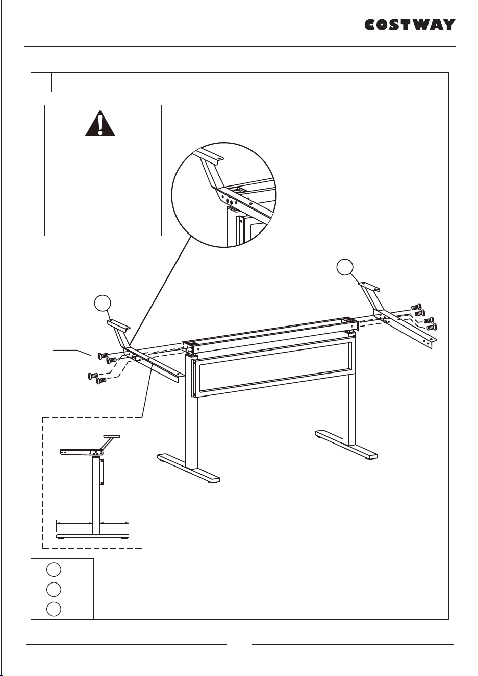
Do not tighten the screws too much
until they are fully assembled to avoid
misalignment of the screw holes.
3
Cx4
Make sure that the opening of part 3
faces upwards during installation.
1
M6*20mm
Bx12
M6*30mm
Cx4
M6*10mm
Dx8Ax1
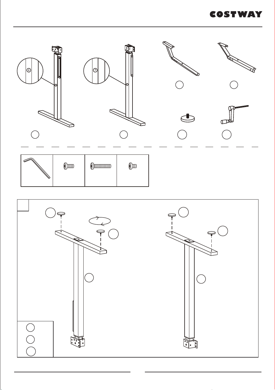
6 x 1 7 x 1
8 x 1 9 x 1
10 x 4 11 x 1
10
10
10
10
7
6
6 x1
7 x1
10 x4
04 05
2
3
Rotate the haxagonal bar
(Part 5 ) if it can’t insert
into the hole smoothly.
5
7
6
5 x1
6 x1
7 x1
3 x2
C x4
Do not tighten the screws too much
until they are fully assembled to avoid
misalignment of the screw holes.
3
Cx4
Make sure that the opening of part 3
faces upwards during installation.
1
M6*20mm
Bx12
M6*30mm
Cx4
M6*10mm
Dx8Ax1
6 x 1 7 x 1
8 x 1 9 x 1
10 x 4 11 x 1
10
10
10
10
7
6
6 x1
7 x1
10 x4
04 05

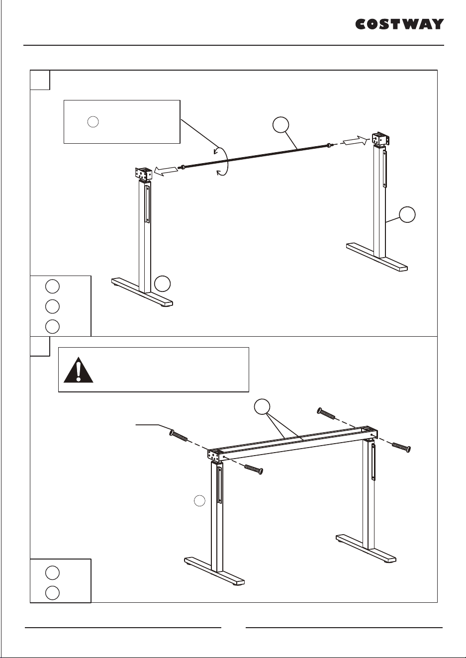
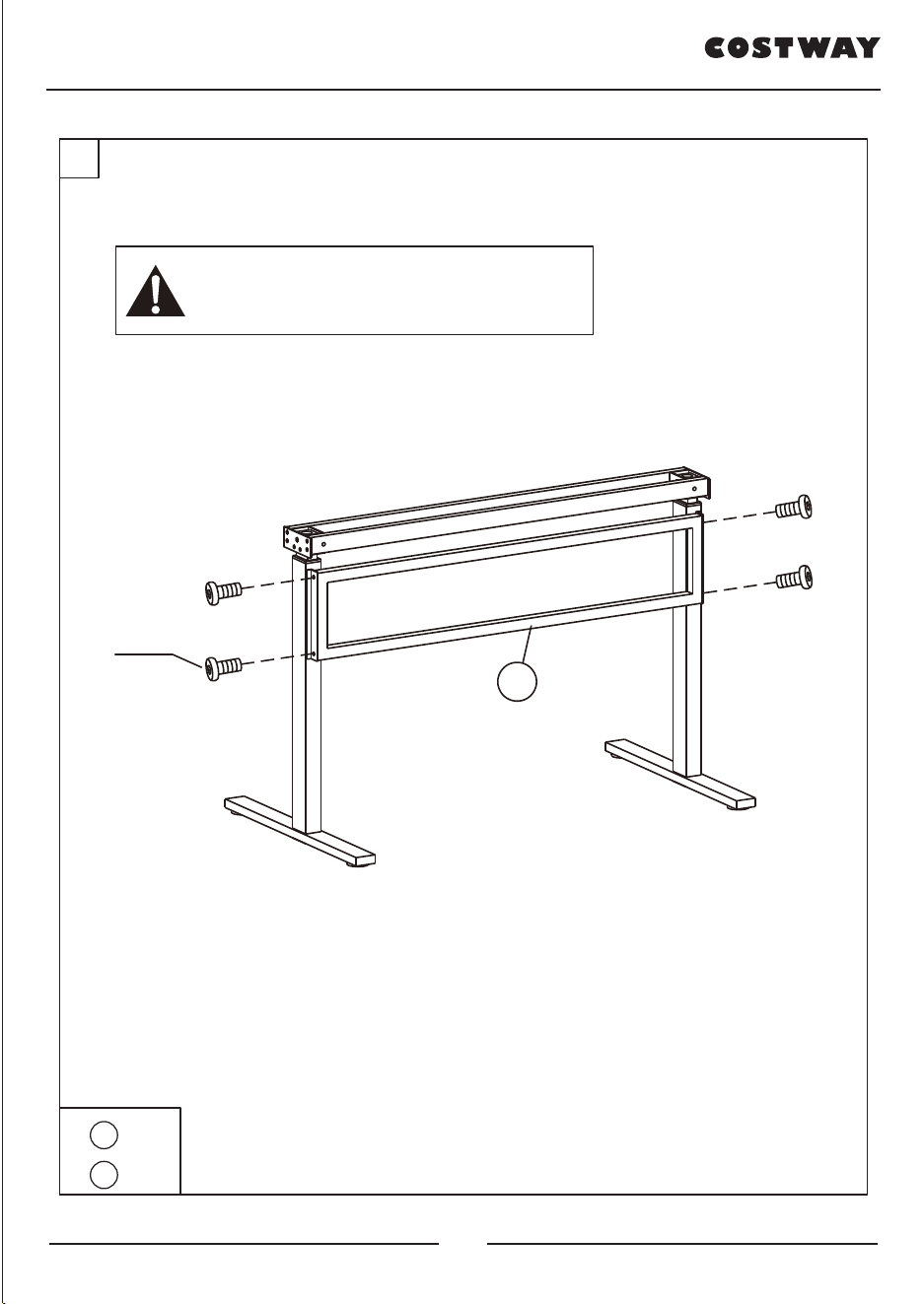
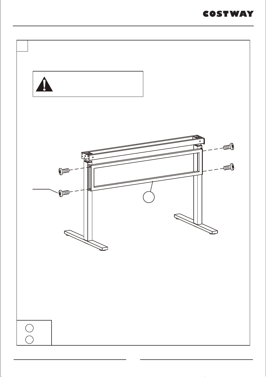
4
4 x1
B x4
Do not tighten the screws too much
until they are fully assembled to avoid
misalignment of the screw holes.
4
Bx4
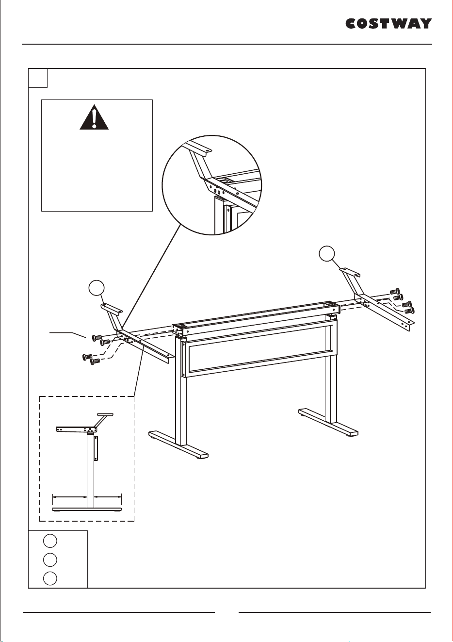
5
9 x1
8 x1
B x8
Do not tighten the screws
too much until they are
fully assembled to avoid
misalignment of the screw
holes.
8
9
Bx8
FRONT
300 240
BACK
Please make sure the bracket
is facing outwards.
06 07

4
4 x1
B x4
Do not tighten the screws too much
until they are fully assembled to avoid
misalignment of the screw holes.
4
Bx4
5
9 x1
8 x1
B x8
Do not tighten the screws
too much until they are
fully assembled to avoid
misalignment of the screw
holes.
8
9
Bx8
FRONT
300 240
BACK
Please make sure the bracket
is facing outwards.
06 07

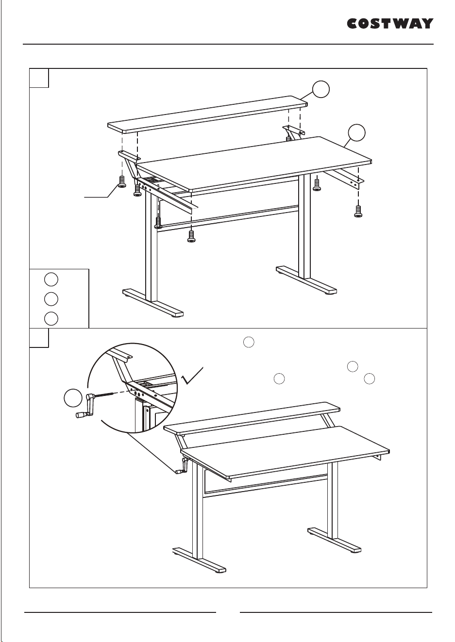
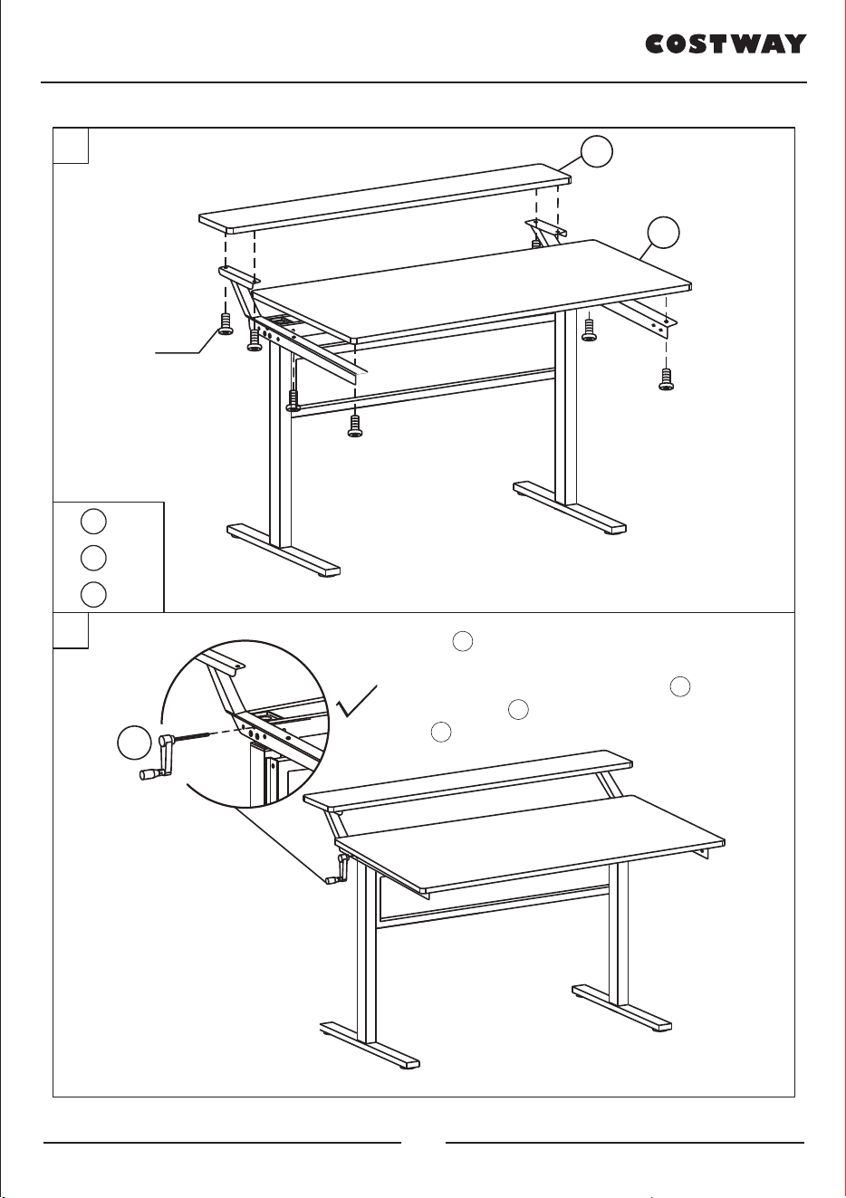
6
7
1 x1
2 x1
D x8
Dx8
1
2
Now tighten all screws and set up the table top.
11
Slight noise on the crank during
use is normal, few lubricants
could solve the problem and it
won't affect the function of the
desk. Any other questions please
contact us.
The part 11 could be installed on both left and
right side of the desk. Rotate the hexagonal bar
(Part 5 ) with Crank Handle(Part 11 ) if you
can’t insert the Part 11 smoothly.
08 09
DAS HANDBUCH ENTHÄLT WICHTIGE SICHERHEITSHINWEISE. BITTE LESEN UND BEWAHREN SIE FÜR DIE ZUKÜNFTIGE VERWENDUNG AUF.
HANDBUCH
EN DE FR IT PL
Faltbarer Computertisch
HW65656
10 11

DAS HANDBUCH ENTHÄLT WICHTIGE SICHERHEITSHINWEISE. BITTE LESEN UND BEWAHREN SIE FÜR DIE ZUKÜNFTIGE VERWENDUNG AUF.
HANDBUCH
EN DE FR IT PL
Faltbarer Computertisch
HW65656
10 11
1
M6*20mm
Bx12
M6*30mm
Cx4
M6*10mm
Dx8Ax1
6 x 1 7 x 1
8 x 1 9 x 1
10 x 4 11 x 1
10
10
10
10
7
6
6 x1
7 x1
10 x4
SEHR GEEHRTER KUNDE
Vielen Dank, dass Sie sich für unsere Produkte entschieden haben. Lesen Sie
dieses Handbuch sorgfältig durch, bevor Sie die Produkte zusammenbauen, um
Schäden durch unsachgemäße Verwendung zu vermeiden. Wir freuen uns sehr,
wenn Sie Feedback geben können, wenn Sie mit unseren Produkten und unserem
Service zufrieden Sind. Oder kontaktieren Sie uns über Amazon, falls ein
Assistent benötigt wird. Wir werden das Problem sicherlich in vollem Umfang
lösen :)
STÜCKLISTE :
Ziehen Sie die Schrauben nicht zu fest an, bis sie vollständig
montiert Sind, um zu vermeiden, dass die Schraubenlöcher nicht
ausgerichtet Sind.
1 x 1
4 x 1 5 x 1
2 x 1 3 x 2
12 13
2
3
Drehen Sie die
Sechskantstange (Teile 5 ),
wenn sie nicht reibungslos in
das Loch eingeführt werden
kanno
5
7
6
5 x1
6 x1
7 x1
3 x2
C x4
Ziehen Sie die Schrauben nicht zu fest an, bis sie
vollständig montiert sind, um eine Fehlausrichtung
der Schraubenlöcher zu vermeiden.
3
Cx4
Stellen Sie sicher, dass die Öffnung
von Teil 3 während der Installation
nach oben zeigt.
4
4 x1
B x4
Ziehen Sie die Schrauben nicht zu fest an, bis sie
vollständig montiert sind, um eine Fehlausrichtung
der Schraubenlöcher zu vermeiden.
4
Bx4
14 15
6
7
1 x1
2 x1
D x8
Dx8
1
2
Ziehen Sie nun alle Schrauben fest und stellen
Sie die Tischplatte auf.
11
Leichte Geräusche an der Kurbel
während des Gebrauchs sind
normal, nur wenige
Schmiermittel können das
Problem lösen und
beeinträchtigen die Funktion des
Schreibtisches nicht. Bei
weiteren Fragen wenden Sie sich
bitte an uns.
Das Teil 11 kann sowohl auf der linken als auch auf
der rechten Seite des Schreibtisches installiert werden.
Drehen Sie die Sechskantstange (Teil 5 ) mit dem
Kurbelgriff (Teil 11 ), wenn Sie das Teil 11 nicht
reibungslos einsetzen können.
5
9 x1
8 x1
B x8
Ziehen Sie die Schrauben
nicht zu fest an, bis sie
vollständig montiert sind,
um eine Fehlausrichtung
der Schraubenlöcher zu
vermeiden.
8
9
Bx8
VORDERSEITE
300 240
RÜCKSEITE
Bitte stellen Sie sicher,
dass die Halterung nach
außen zeigt.
16 17

CE MANUEL D’INSTRUCTIONS CONTIENT DES INFORMATIONS IMPORTANTES SUR LA SÉCURITÉ. VEUILLEZ LIRE ET CONSERVER POUR LA RÉFÉRENCE FUTURE.
MANUEL DE L’UTILISATEUR
EN DE FR IT PL
Bureau Réglable en Hauteur
HW65656
18 19
CE MANUEL D’INSTRUCTIONS CONTIENT DES INFORMATIONS IMPORTANTES SUR LA SÉCURITÉ. VEUILLEZ LIRE ET CONSERVER POUR LA RÉFÉRENCE FUTURE.
MANUEL DE L’UTILISATEUR
EN DE FR IT PL
Bureau Réglable en Hauteur
HW65656
18 19

CHER CLIENT
Merci d’avoir choisi nos produits, veuillez lire attentivement ce manuel avant
d’assembler le produit afin d’éviter les dommages causés par une mauvaise
utilisation.
Nous vous serions très reconnaissants de nous faire part de vos commentaires
lorsque vous êtes satisfait de nos produits et services. Vous pouvez également
nous contacter à tout moment si vous avez besoin d’un assistant. Nous allons
certainement résoudre le problème :)
LISTE DES PIÈCES:
Ne serrez pas trop les vis avant l’assemblage complet pour éviter
le mauvais alignement des trous de vis.
1 x 1
4 x 1 5 x 1
2 x 1 3 x 2
20 21
2
3
Faites tourner la barre
hexagonale (pièce 5 ),
si elle ne peut pas s’insérer
dans le trou en douceur.
5
7
6
5 x1
6 x1
7 x1
3 x2
C x4
Ne serrez pas trop les vis avant
l’assemblage complet pour éviter le
mauvais alignement des trous de vis.
3
Cx4
Veillez à ce que l’ouverture de la
pièce 3 soit orientée vers le haut
lors de l’installation.
1
M6*20mm
Bx12
M6*30mm
Cx4
M6*10mm
Dx8Ax1
6 x 1 7 x 1
8 x 1 9 x 1
10 x 4 11 x 1
10
10
10
10
7
6
6 x1
7 x1
10 x4
22 23
4
4 x1
B x4
Ne serrez pas trop les vis avant
l’assemblage complet pour éviter le
mauvais alignement des trous de vis.
4
Bx4
5
9 x1
8 x1
B x8
Ne serrez pas trop les vis
avant l’assemblage complet
pour éviter le mauvais
alignement des trous de vis.
8
9
Bx8
AVA N T
300 240
ARRIÈRE
Veuillez vous assurer que le
support est orienté vers
l’extérieur.
24 25

4
4 x1
B x4
Ne serrez pas trop les vis avant
l’assemblage complet pour éviter le
mauvais alignement des trous de vis.
4
Bx4
5
9 x1
8 x1
B x8
Ne serrez pas trop les vis
avant l’assemblage complet
pour éviter le mauvais
alignement des trous de vis.
8
9
Bx8
AVA N T
300 240
ARRIÈRE
Veuillez vous assurer que le
support est orienté vers
l’extérieur.
24 25
6
7
1 x1
2 x1
D x8
Dx8
1
2
Maintenant, serrez toutes les vis et installez le
plateau de la table.
11
Un léger bruit sur la manivelle
lors de l’utilisation est normal,
peu de lubrifiant pourrait
résoudre le problème et cela
n’affectera pas l’utilisation du
bureau.
Pour toute autre question,
veuillez nous contacter.
La pièce 11 peut être installée à gauche et à droite
du bureau.
Faites tourner la barre hexagonale (pièce 5 ) avec la
manivelle (pièce 11 si vous ne pouvez pas insérer la
pièce 11 en douceur.
26 27
QUESTO MANUALE DI ISTRUZIONI CONTIENE IMPORTANTI INFORMAZIONI SULLA SICUREZZA. SI PREGA DI LEGGERE E CONSERVARE PER RIFERIMENTO FUTURO.
MANUALE UTENTE
EN DE FR IT PL
Scrivania
HW65656
28 29

QUESTO MANUALE DI ISTRUZIONI CONTIENE IMPORTANTI INFORMAZIONI SULLA SICUREZZA. SI PREGA DI LEGGERE E CONSERVARE PER RIFERIMENTO FUTURO.
MANUALE UTENTE
EN DE FR IT PL
Scrivania
HW65656
28 29

1
M6*20mm
Bx12
M6*30mm
Cx4
M6*10mm
Dx8Ax1
6 x 1 7 x 1
8 x 1 9 x 1
10 x 4 11 x 1
10
10
10
10
7
6
6 x1
7 x1
10 x4
CARO CLIENTE
Grazie per aver scelto i nostri prodotti, si prega di leggere attentamente questo
manuale prima di assemblare i prodotti per evitare danni causati da un uso
improprio.
Siamo molto apprezzati se puoi lasciare un commento se sei soddisfatto dei
nostri prodotti e servizi. Oppure contattaci in qualsiasi momento se hai bisogno
di assistenza. Sicuramente risolveremo il problema a tutto campo :)
ELENCO DELLE PARTI:
Non stringere eccessivamente le viti fino a quando non sono
completamente assemblate per evitare disallineamenti dei fori
delle viti.
1 x 1
4 x 1 5 x 1
2 x 1 3 x 2
30 31

2
3
Ruota la barra esagonale
(Parte 5 ) se non è possibile
inserirla nel foro senza
problemi.
5
7
6
5 x1
6 x1
7 x1
3 x2
C x4
Non stringere troppo le viti fino a quando non sono
completamente assemblate per evitare
disallineamenti dei fori delle viti.
3
Cx4
Assicurarsi che l'apertura della
parte 3 sia rivolta verso l'alto
durante l'installazione.
4
4 x1
B x4
Non stringere troppo le viti fino a quando non sono
completamente assemblate per evitare
disallineamenti dei fori delle viti.
4
Bx4
32 33
6
7
1 x1
2 x1
D x8
Dx8
1
2
Ora stringete tutte le viti e sistemate il piano
del tavolo.
11
Un leggero rumore sulla
pedivella durante l'uso è
normale, pochi lubrificanti
potrebbero risolvere il problema
e non influirebbero sul
funzionamento della scrivania.
Per qualsiasi altra domanda non
esitate a contattarci.
La parte 11 potrebbe essere installata sia sul lato
sinistro che su quello destro della scrivania. Ruotare la
barra esagonale (parte 5 ) con la manovella
(parte 11 ) se non è possibile inserire la parte 11
senza problemi.
5
9 x1
8 x1
B x8
Non stringere troppo le viti
fino a quando non sono
completamente assemblate
per evitare disallineamenti
dei fori delle viti.
8
9
Bx8
FRONTE
300 240
INDIETRO
Assicurarsi che la staffa
sia rivolta verso l'esterno.
34 35

NINIEJSZA INSTRUKCJA ZAWIERA
ISTOTNE
INFORMACJE DOTYCZĄCE BEZPIECZEŃSTWA. PROSIMY O ZAPOZNANIE SIĘ Z NIĄ I ZACHOWANIE JEJ DO WGLĄDU W PRZYSZŁOŚCI.
INSTRUKCJA OBSŁUGI
EN DE FR IT PL
Biurko z wysuwanym blatem
HW65656
36 37

NINIEJSZA INSTRUKCJA ZAWIERA
ISTOTNE
INFORMACJE DOTYCZĄCE BEZPIECZEŃSTWA. PROSIMY O ZAPOZNANIE SIĘ Z NIĄ I ZACHOWANIE JEJ DO WGLĄDU W PRZYSZŁOŚCI.
INSTRUKCJA OBSŁUGI
EN DE FR IT PL
Biurko z wysuwanym blatem
HW65656
36 37

DROGI KLIENCIE,
Dziękujemy za wybranie naszych produktów; prosimy uważnie przeczytać
niniejszą instrukcję przed montażem produktu, aby uniknąć uszkodzeń
spowodowanych niewłaściwym użytkowaniem. Jesteśmy bardzo wdzięczni za
każdą pozytywną opinię na temat naszych produktów I świadczonych usług.
Skontaktuj się z nami w dowolnym momencie, gdy potrzebujesz pomocy
naszego asystenta. Z pewnością rozwiążemy problem w pełnym zakresie :)
LISTA CZĘŚCI:
Nie dokręcaj śrub zbyt mocno, dopóki nie zostaną one całkowicie
zmontowane, celem uniknięcia problemów z niewspółosiowością
otworów na śruby.
1 x 1
4 x 1 5 x 1
2 x 1 3 x 2
38 39
2
3
Obróć kluczem
imbusowym 5 , jeśli nie
możesz umieścić go w
otworze z należytą
łatwością.
5
7
6
5 x1
6 x1
7 x1
3 x2
C x4
Nie dokręcaj śrub zbyt mocno, dopóki nie zostaną
całkowicie zmontowane, celem uniknięcia problemów
związanych z niewspółosiowością otworów na śruby
3
Cx4
Upewnij się, że otwór części 3 jest
skierowany do góry podczas
instalacji.
1
M6*20mm
Bx12
M6*30mm
Cx4
M6*10mm
Dx8Ax1
6 x 1 7 x 1
8 x 1 9 x 1
10 x 4 11 x 1
10
10
10
10
7
6
6 x1
7 x1
10 x4
40 41
4
4 x1
B x4
Nie dokręcaj śrub zbyt mocno, dopóki nie zostaną
całkowicie zmontowane, celem uniknięcia problemów
związanych z niewspółosiowością otworów na śruby.
4
Bx4
5
9 x1
8 x1
B x8
Nie dokręcaj śrub zbyt
mocno, dopóki nie zostaną
całkowicie zmontowane,
celem uniknięcia
problemów związanych z
niewspółosiowością
otworów na śruby.
8
9
Bx8
PRZÓD
300 240
TYŁ
Upewnij się, że wspornik
jest skierowany na zewnątrz.
42 43
4
4 x1
B x4
Nie dokręcaj śrub zbyt mocno, dopóki nie zostaną
całkowicie zmontowane, celem uniknięcia problemów
związanych z niewspółosiowością otworów na śruby.
4
Bx4
5
9 x1
8 x1
B x8
Nie dokręcaj śrub zbyt
mocno, dopóki nie zostaną
całkowicie zmontowane,
celem uniknięcia
problemów związanych z
niewspółosiowością
otworów na śruby.
8
9
Bx8
PRZÓD
300 240
TYŁ
Upewnij się, że wspornik
jest skierowany na zewnątrz.
42 43

6
7
1 x1
2 x1
D x8
Dx8
1
2
Teraz dokręć wszystkie śruby i ustaw
odpowiednio blat stołu.
11
Hałas korby podczas
użytkowania jest normalny, wiele
środków smarnych może
rozwiązać ten problem i nie
wpłynie to negatywnie na
działanie biurka. Wszelkie inne
pytania prosimy zadawać przy
kontakcie z konsultantem naszej
firmy.
Część nr 11 można zainstalować po lewej i prawej
stronie biurka.
Obróć klucz imbusowy 5 za pomocą korby 11 ,
jeśli nie możesz umieścić części nr 11 z należytą
łatwością.
44 45