1 3
N
L
2
1 23
L
1
23
4
5
6
100
%
90
80
70
60
50
Montageanleitung
Assembly instructions
Notice de montage
Montage-instruktie
Montageanvisning
Istruzioni di montaggio
Instrucciones de montaje
Enclosures
Power Distribution
Climate Control
IT Infrastructure
Software & Services
RITTAL GmbH & Co. KG
Postfach 1662 · D-35726 Herborn
Phone + 49(0)2772 505-0 · Fax + 49(0)2772 505-2319
E-mail: info
@
rittal.de · www.rittal.com
2. Aufl . 1.2014 / Id-Nr. 232 589
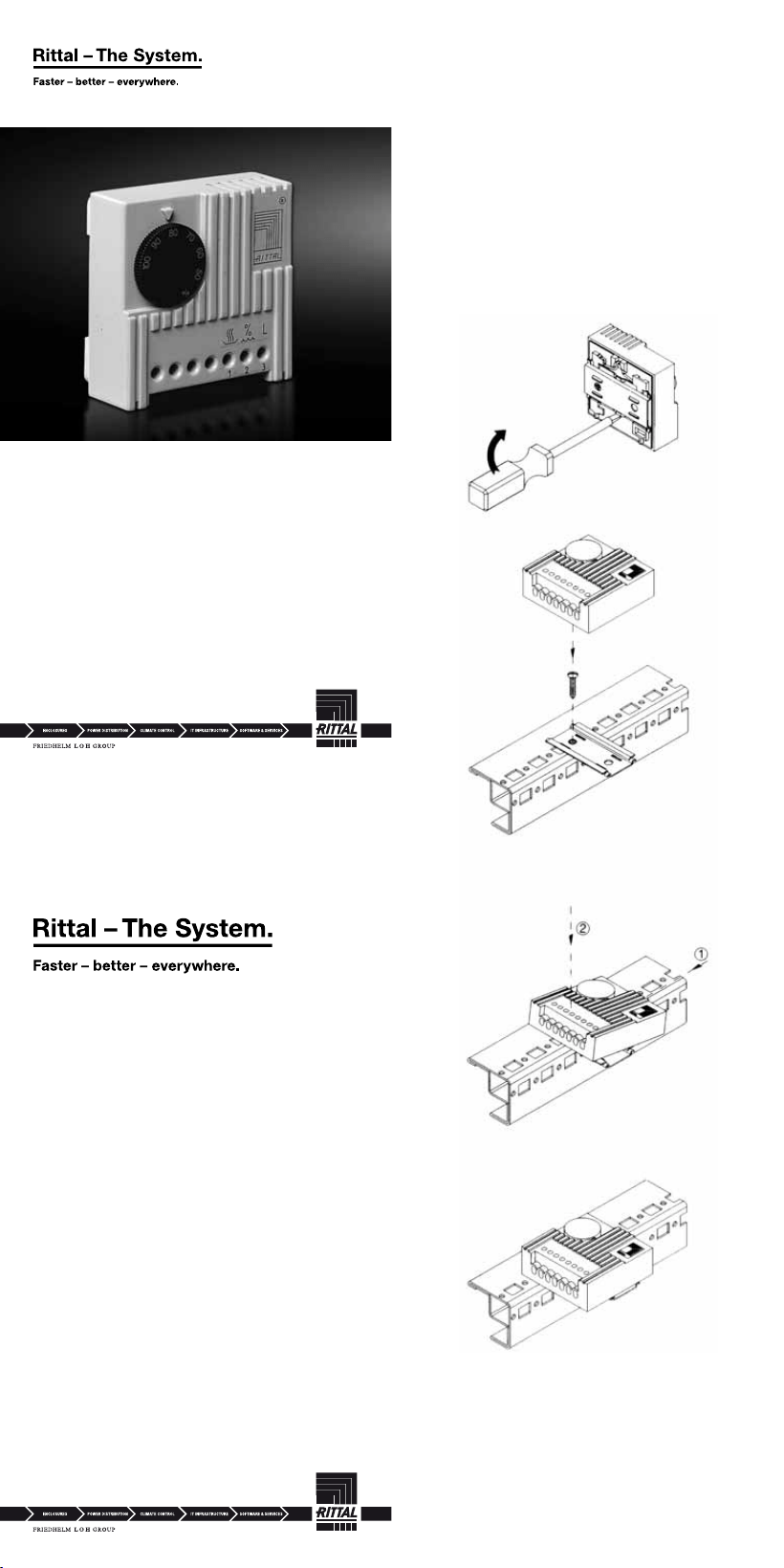
Abb. 1: Schnappbefestigung auf 35 mm-Tragschiene
nach EN 50 022
Fig. 1: Clip-on fastening on 35 mm support rail
to EN 50 022
Fig. 1: Fixation par encliquetage sur rail porteur
de 35 mm selon EN 50 022
Afb. 1: Snapbevestiging op 35 mm montagerail
volgens EN 50 022
Bild 1: Snäppfastsättning på 35 mm profi lskena
enligt EN 50 022
Fig. 1: Fissaggio a scatto su guida a 35 mm
secondo EN 50 022
Fig. 1: Clips de sujeción sobre guía soporte
de 35 mm según EN 50 022
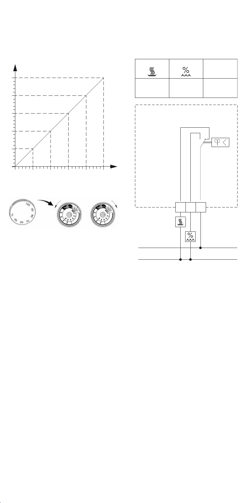
Abb. 2: Bereichseinengung
Fig. 2: Range restriction
Fig. 2: Réduction de la plage de température
Afb. 2: Instelling van het bereik
Bild 2: Anslutningssättet
Fig. 2: Limitazione di campo della temperatura
Fig. 2: Ajuste del campo de temperatura
Einstellbereich Hygrostat
Bereichseinengung im Einstellknopf
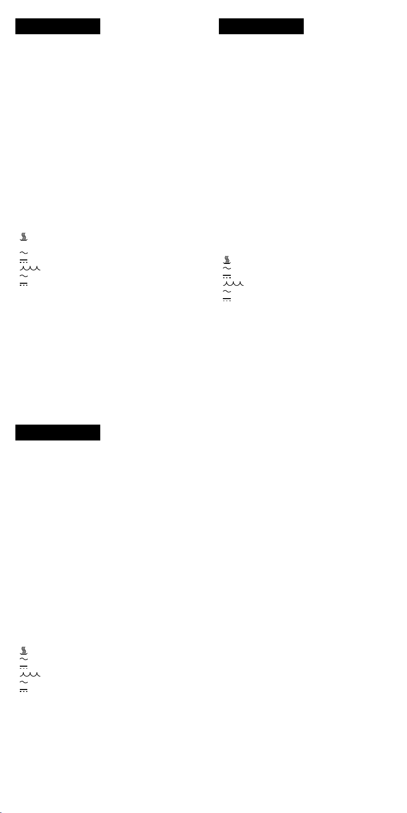
Abb. 3: Anschlussschema
Fig. 3: Connection diagram
Fig. 3: Schéma de connexion
Afb. 3: Aansluitschema
Bild 3: Anslutningsschema
Fig. 3: Schema di allacciamento
Fig. 3: Esquema de conexión
max. min.
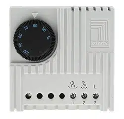
Hygrostat
Hygrostat
Hygrostat
Hygrostaat
Hygrostat
Igrostato
Higrostato
3118.000
1 3
N
L
2
1 23
L
1
23
4
5
6
100
%
90
80
70
60
50
Montageanleitung
Assembly instructions
Notice de montage
Montage-instruktie
Montageanvisning
Istruzioni di montaggio
Instrucciones de montaje
Enclosures
Power Distribution
Climate Control
IT Infrastructure
Software & Services
RITTAL GmbH & Co. KG
Postfach 1662 · D-35726 Herborn
Phone + 49(0)2772 505-0 · Fax + 49(0)2772 505-2319
E-mail: info
@
rittal.de · www.rittal.com
2. Aufl . 1.2014 / Id-Nr. 232 589
Abb. 1: Schnappbefestigung auf 35 mm-Tragschiene
nach EN 50 022
Fig. 1: Clip-on fastening on 35 mm support rail
to EN 50 022
Fig. 1: Fixation par encliquetage sur rail porteur
de 35 mm selon EN 50 022
Afb. 1: Snapbevestiging op 35 mm montagerail
volgens EN 50 022
Bild 1: Snäppfastsättning på 35 mm profi lskena
enligt EN 50 022
Fig. 1: Fissaggio a scatto su guida a 35 mm
secondo EN 50 022
Fig. 1: Clips de sujeción sobre guía soporte
de 35 mm según EN 50 022
Abb. 2: Bereichseinengung
Fig. 2: Range restriction
Fig. 2: Réduction de la plage de température
Afb. 2: Instelling van het bereik
Bild 2: Anslutningssättet
Fig. 2: Limitazione di campo della temperatura
Fig. 2: Ajuste del campo de temperatura
Einstellbereich Hygrostat
Bereichseinengung im Einstellknopf
Abb. 3: Anschlussschema
Fig. 3: Connection diagram
Fig. 3: Schéma de connexion
Afb. 3: Aansluitschema
Bild 3: Anslutningsschema
Fig. 3: Schema di allacciamento
Fig. 3: Esquema de conexión
max. min.
Hygrostat
Hygrostat
Hygrostat
Hygrostaat
Hygrostat
Igrostato
Higrostato
3118.000
Deutsch
Dieses Gerät darf nur von
ausgebildetem Fachperso-
nal gemäß dem Schaltbild
Abb. 3 installiert werden.
Dabei sind die bestehen-
den Sicherheitsvorschriften
zu beachten.
Dieser Schaltschrank-
Hygrostat dient zur
Regelung der relativen
Luftfeuchtigkeit in einem
geschlossenen Schalt-
schrank.
Dieses Gerät ist gemäß
VDE 0875 bzw. EN 55 014
funkentstört.
Technische Ausführung
Ausführung:
Polyamidband als feuch-
teempfi ndliches Organ.
Kontaktbestückung:
1-poliger Umschalt-
kontakt (Wechsler) als
Sprungschaltglied.
Zulässige Kontaktdaten:
Trocknen bzw.
Wärmen:
24 – 250 V, 5 (0,2
1)
) A
24 – 48 V, max. 20 W
Befeuchten:
24 – 250 V, 2 (0,2
1)
) A
24 – 48 V, max. 20 W
Minimalbelastung:
100 mA, 24 V AC/DC
Schaltdifferenz:
ca. 4 % r.F.
1)
Induktive Last
Montage
Schnappbefestigung auf
35 mm-Tragschiene nach
EN 50 022, siehe Abb. 1,
sowohl waagerecht, als
auch senkrecht durch Ver-
setzen der Klemmfeder.
Hinweise
Die Montage ist in hori-
zontaler Lage vorzuneh-
men. Die Platzierung des
Hygrostats sollte nach
Möglichkeit diagonal im
oberen Schaltschrankbe-
reich mit größtmöglichem
Abstand zu Schaltschrank-
Heizungen und Verlust-
wärmequellen gewählt
werden.
Die Bereichseinengung
kann entsprechend Abb. 2
vorgenommen werden.
Bei fl exiblen Anschluss-
leitungen (Litzen) sind
Aderendhülsen zu ver-
wenden.
Garantie
Auf dieses Gerät gewähren
wir 1 Jahr Garantie bei
fachgerechter Anwendung
vom Tage der Lieferung
an. Innerhalb dieses
Zeitraumes wird das ein-
geschickte Gerät im Werk
kostenlos repariert oder
ausgetauscht.
English
This component must
be installed by fully
trained personnel only, in
accordance with wiring
diagram Fig. 3.
Relevant safety regulations
must be observed. These
enclosure hygrostat are
used to control the relative
humidity inside a closed
enclosure. This unit is RFI
screened in accordance
with VDE 0875 and/or
EN 55 014.
Technical details
Construction:
Polyamide tape as
a humidity sensitive
element.
Contacts:
Single-pole changer as a
quick-break switch.
Permissible contact data:
Drying or heating:
24 – 250 V, 5 (0.2
1)
) A
24 – 48 V, max. 20 W
Humidifying:
24 – 250 V, 2 (0.2
1)
) A
24 – 48 V, max. 20 W
Minimum charge:
100 mA, 24 V AC/DC
Operational differential:
approx. 4% r.h.
Temperature:
Maximum ambient oper-
ating Temperature: 60°C
Shipping and Storage
Temperature: -30°C to
70°C (-40°C for Canada)
Overvoltage Category: III
Pollution Degree: 2
1)
Inductive load
Mounting
Clip-on fastening on
35 mm support rail to
EN 50 022, see Fig. 1.
Notes
Mounting should preferably
be executed in the hori-
zontal position. Wherever
possible, the hygrostat
should be placed in the
upper part of the enclosure
with maximum separation
from the enclosure heaters
and sources of heat losses.
Range restriction can be
made in accordance with
Fig. 2.
Guarantee
This unit is guaranteed for
1 year, subject to correct
usage from the date of
delivery. Within that period,
the returned unit will be
repaired in thefactory or
replaced free of charge.
Svenska
Denna enheft får endast
installeras av utbildat
personal enligt Bild 3.
Hänsyn skall tagas till
gällande säkerhets-
föreskrifter.
Denna apparatskåps-
hygrostat reglerar relativ
luftfuktighet i ett slutet
apparatskåp.
Aggregatet är kontrollerat
enligt VDE 0875 och
EN 55 014 radioavstört.
Tekniskt uttförande
Utförande:
Som fuktkännande organ
används ett polyamid-
band.
Kontaktbestyckning:
1-polig växlandekontakt.
Tillåten kontakt-
bestyckning:
Upptorkning eller
uppvärmning:
24 – 250 V, 5 (0,2
1)
) A
24 – 48 V, max. 20 W
Befuktning:
24 – 250 V, 2 (0,2
1)
) A
24 – 48 V, max. 20 W
Minimalbelastning:
100 mA, 24 V AC/DC
Kopplingsdifferens:
ca. 4 % r.f.
1)
Induktiv last
Montage
Snäppfastsättning av
35 mm plintskena enligt
EN 50 022, se Bild 1.
Inbyggnadsanvisning
Montaget bör ske i horison-
tellt läge. Placeringen av
termostaten bör vara i den
övre delen i skåpet och så
långt från värmeelement
och värmekällor som
möjligt. Anslutningssättet
kan ses på Bild 2.
Garanti
Vi garanterar 1 års garanti
vid fackmannamässigt
användande från leve-
ransdatum. Inom denna
tid kommer aggregatet att
repareras eller bytas ut
kostnadsfritt.
Italiano
Questo apparecchio può
essere installato solo da
personale specializzato
in base allo schema di
montaggio Fig. 3, rispet-
tando le norme di sicu-
rezza relative allo stesso.
L’igrostato serve per
regolare l’umidità relativa
interna in un armadio
chiuso. Questo apparec-
chio è schermato sec.
VDE 0875 e rispettiva-
mente EN 55 014.
Esecuzione tecnica
Esecuzione:
Elemento sensibile
all’umidità realizzato in
poliammide fi liforme.
Contatto di commutazione
a scatto, unipolare.
Carico ammesso al
contatto:
Deumidifi cazione:
24 – 250 V, 5 (0,2
1)
) A
24 – 48 V, max. 20 W
Umidifi cazione:
24 – 250 V, 2 (0,2
1)
) A
24 – 48 V, max. 20 W
Portata minima:
100 mA, 24 V AC/DC
Differenza allo scatto:
ca. 4 % u.r.
1)
Carico induttivo
Montaggio
Fissaggio a scatto sulla
guida portante a 35 mm
sec. EN 50 022,
vedi Fig. 1.
Informazioni
Si consiglia un’installazione
orizzontale.
L’igrostato dovrebbe
essere installato pos-
sibilmente nella parte
superiore dell’armadio;
considerando una notevole
distanza sia da riscaldatori
anticondensa o da fonti di
dissipazione di calore. Per
la limitazione di campo fare
riferimento alla Fig. 2.
Per la connessioni di
conduttori fl essibili
utilizzare terminali a
puntalino.
Garanzia
Per questo apparecchio
concediamo un anno di
garanzia con decorrenza
dal giorno della fornitura,
per un impiego appro-
priato e nelle condizioni
previste. In caso di guasti
entro tale periodo di tempo
l’apparecchio potrà essere
inviato in fabbrica, dove si
eseguirà una riparazione o
una sostituzione gratuita.
Español
La instalación de este
aparato debe realizzarla
exclusivamente personal
espezializado según el
diagrama de circuito
de la Fig. 3. Durante la
instalación deben tenerse
en cuenta las normas de
seguridad. Este higrostato
para armarios de distribu-
ción regula la humedad
relativa del aire en un
armario cerrado. Aparato
libre de interferencias
según VDE 0875 o bien
EN 55 014.
Descripción técnica
Descripción:
Banda de poliamida sen-
sible a la humedad.
Componentes del
contacto:
1 contacto conmutado.
Datos del contacto
admitidos:
Secar o calentar:
24 – 250 V, 5 (0,2
1)
) A
24 – 48 V, máx. 20 W
Humedecer:
24 – 250 V, 2 (0,2
1)
) A
24 – 48 V, máx. 20 W
Carga mínima:
100 mA, 24 V c.a./c.c.
Histéresis:
aprox. 4 % h.r.
1)
Carga inductiva
Montaje
Sujeción con clips a la guía
soporte de 35 mm según
EN 50 022, ver Fig. 1.
Indicaciones
Es preferible realizar el
montaje en posición hori-
zontal. El emplazamiento
del higrostato debería ser
en la parte superior del ar-
mario a la máxima distan-
cia posible de resistencias
calefactoras y fuentes de
evacuación de calor.
El ajuste del campo de
temperatura puede reali-
zarse según Fig. 2.
Garantía
Sobre esta unidad otor-
gamos 1 año de garantía
contado a partir del día de
suministro, siempre que
su utilización se efectúe
de forma correcta. Dentro
de este período la unidad
suministrada será repara-
do o sustituida en fábrica
gratuitamente.
Français
Seul le personnel qualifi é
est autorisé à installer
l’appareil conformément
au schéma de connexion,
Fig. 3. Les directives de
sécurité en vigueur
doivent absolument être
respsectées. Le hygrostat
permet d’assurer le
réglage de la humidité
relative de l’air de l’armoire
électrique lorsque celle-ci
est fermée.
L’appareil est antiparasité
conformément aux normes
VDE 0875 ou EN 55 014.
Fabrication technique
Fabrication:
L’organe sensible à la
humidité est une bande
en polyamide.
Elément de contact:
Contact unipolaire (inver-
seur) comme élément de
rupture brusque.
Données admissibles pour
le contact:
Sécher ou chauffer:
24 – 250 V, 5 (0,2
1)
) A
24 – 48 V, max. 20 W
Humidifi er:
24 – 250 V, 2 (0,2
1)
) A
24 – 48 V, max. 20 W
Charge minimale:
100 mA, 24 V AC/DC
Difference
d’enclenchement:
env. 4 % h.r.
1)
Charge inductive
Montage
Fixation par encliquetage
sur rail porteur de 35 mm
selon EN 50 022,
voir Fig. 1.
Remarque
Le montage se fera de
préférence en position
horizontale. Installer le
hygrostat dans la partie
supérieure de l’armoire
électrique en l’écartant
le plus possible des
resistances chauffantes
pour armoires électriques
et de toutes les sources de
dissipation de chaleur.
Pour réduire la plage de
hygrostat, se conformer
aux indications de la Fig. 2.
Garantie
Nous assurons sur l’appa-
reil utilisé correctement une
garantie de 1 an à compter
du jour de la livraison.
Durant cette période, un
appareil renvoyé à nos
ateliers sera réparé ou
échangé gratuitement.
Nederlands
Het apparaat mag alleen
dor vakkundige personen
overeenkomstig Afb. 3
geïnstalleerd worden.
Daarbij dienen de
bestaande veiligheids-
voorschriften in acht te
worden genomen. Deze
hygrostaat dient voor de
regeling van de relatieve
luchtvochtigheid in een
gesloten schakelkast.
Dit apparaat is ontstoord
overeenkomstig VDE 0875
resp. EN 55 014.
Technische uitvoering
Uitvoering:
Polyamideband als
vochtgevoelige opnemer.
Kontaktuitvoering:
1-polig wisselkontakt
met schakelmoment.
Toelaatbare kontakt-
belasting:
Drogen, bijv.
verwarmen:
24 – 250 V, 5 (0,2
1)
) A
24 – 48 V, max. 20 W
Bevochtigen:
24 – 250 V, 2 (0,2
1)
) A
24 – 48 V, max. 20 W
Minimale belasting:
100 mA, 24 V AC/DC
Schakeldifferentie:
ca. 4 % r.v.
1)
Induktieve belasting
Montage
Snapbevestiging op
35 mm dinrail volgens
EN 50 022, zie Afb. 1.
Aanwijzing
De montage bijvoorkeur
in horizontale positie.
De hygrostaat zal, als
dit mogelijk is, geplaatst
moeten worden in het
bovenste gedeelte van
de schakelkast. Zo ver
mogelijk verwijderd van
schakelkastverwarmingen
en andere bronnen met
een grote warmteafstraling.
De instelling van het bereik
kan overeenkomstig Afb. 2
worden gerealiseerd.
Garantie
Op dit apparaat garande-
ren wij 1 jaar garantie bij
vakkundig gebruik vanaf
de dag van levering.
Binnen dit tijdsbestek
wordt het retourgezonden
apparaat kostenloos
gereppareerd of uitge-
wisseld.
