Loading ...
Loading ...
Loading ...
96
When the trigger point is located on the left side to the center line of the waveform display area, the delay
time is displayed as a positive value; When the trigger point is located on the right side to the time reference
point , and the delay time is displayed as a negative value; the trigger point overlaps with the center line of
the waveform display area, and the delay time is zero.
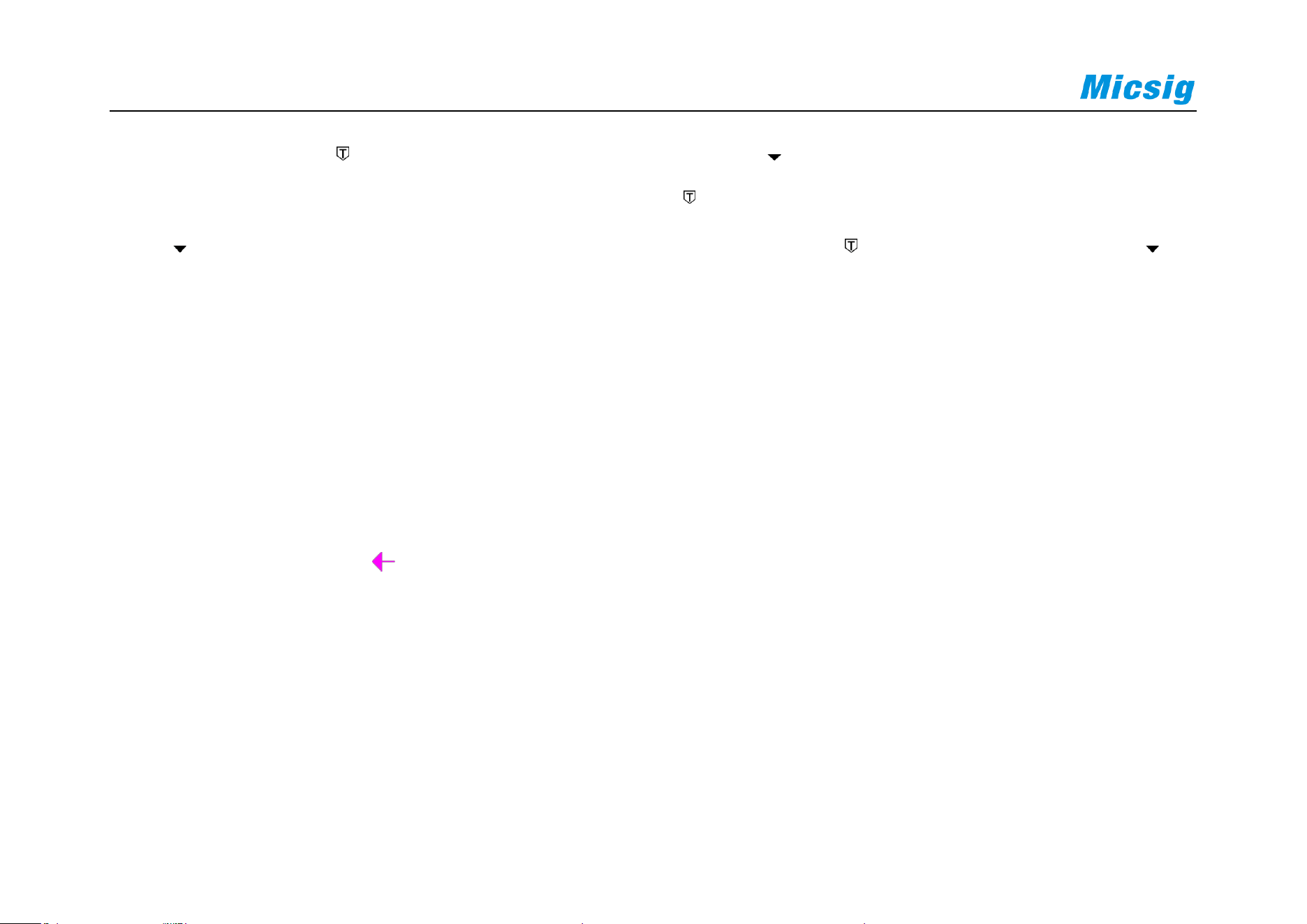
Trigger level
Trigger level is the signal voltage corresponding to the set trigger point. When the trigger level is changed, a
horizontal line will appear temporarily on the screen to tell you the level position (the specific value of the trigger
level is displayed in the upper right corner of the screen), then the horizontal line disappears, the trigger level is
indicated by a small arrow and the indication icon can be dragged to adjust the trigger level value. The trigger
level is shown in Figure 6-8 (the arrow indicates the trigger level line).
Loading ...
Loading ...
Loading ...