Loading ...
Loading ...
Loading ...
291, 292, 294
Users Manual
Arbitrary waveforms have a user defined length of 8 to 1,048,576 points. Square waves
use a fixed length of 2 points and pulse and pulse train have their length defined by the
user selected period value.
DDS Mode
In DDS mode all waveforms are stored in RAM as 4096 points. The frequency of the
output waveform is determined by the rate at which the RAM addresses are changed.
The address changes are generated as follows:
The RAM contains the amplitude values of all the individual points of one cycle (360 º)
of the waveform; each sequential address change corresponds to a phase increment of the
waveform of 360/4096 degrees. Instead of using a counter to generate sequential RAM
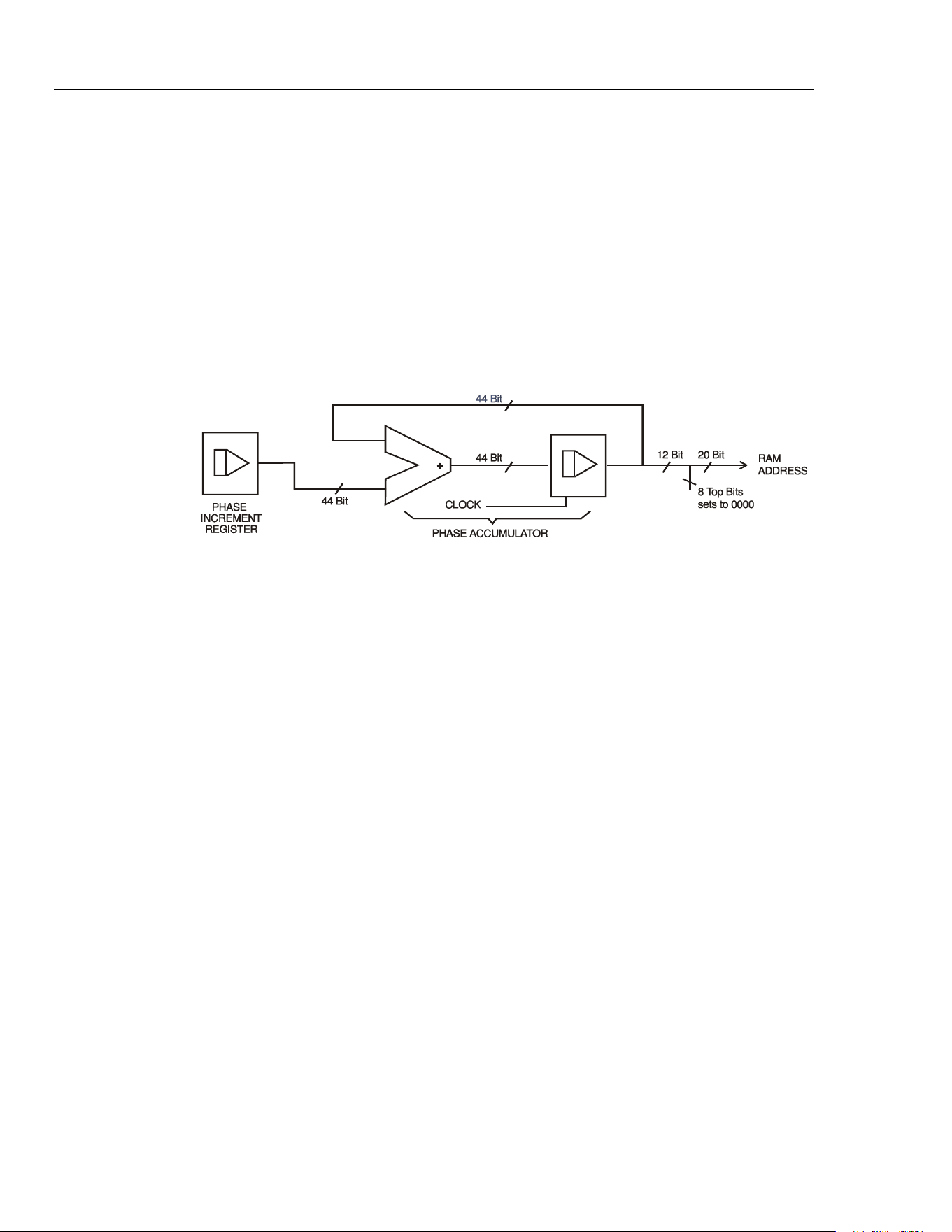
addresses, a phase accumulator is used to increment the phase.
shc0006f.emf
Figure 4-3. Direct Digital Synthesis Mode
On each clock cycle the phase increment, which has been loaded into the phase increment
register by the CPU, is added to the current result in the phase accumulator; the 12 most
significant bits of the phase accumulator drive the lower 12 RAM address lines, the upper
8 RAM address lines being held low. The output waveform frequency is now determined
by the size of the phase increment at each clock. If each increment is the same size then
the output frequency is constant; if it changes, the output frequency changes as in sweep
mode.
The generator uses a 44 bit accumulator and a 100 MHz clock frequency; the frequency
setting resolution is 0·1 mHz.
Only the 12 most significant bits of the phase accumulator are used to address the RAM.
At a waveform frequency equal to the clock frequency divided by 4096, approximately
24.4 kHz, the natural frequency, the RAM address increments at every clock. At all
frequencies below this (i.e. at smaller phase increments) one or more addresses are output
for more than one clock period because the phase increment is not big enough to step the
address at every clock. Similarly at frequencies above the natural frequency the larger
phase increment causes some addresses to be skipped, giving the effect of the stored
waveform being sampled; different points will be sampled on successive cycles of the
waveform.
4-6
1.888.610.7664 sales@GlobalTestSupply.com
Fluke-Direct.com
Loading ...
Loading ...
Loading ...