ALUMINIUM MITRE SAW PROTRACTOR
MODEL NO: SMS7P
Thank you for purchasing a Sealey product. Manufactured to a high standard, this product will, if used according to these
instructions, and properly maintained, give you years of trouble free performance.
I
MP
PO
R
RTA
TA
NT:
PLEA
S
E READ THE
S
E IN
S
TRU
C
TI
O
N
S
C
AREFULLY. N
O
TE THE
S
AFE
O
PERATI
O
NAL RE
Q
UIREMENT
S
, WARNIN
GS
&
C
AUTI
O
N
S
. U
S
E
TH
HE
P
PR
O
ODU
C
T
CO
RRE
C
TLY AND WITH
C
ARE F
O
R THE P
U
RP
OS
E F
O
R WHI
C
H IT I
S
INTENDED. FAIL
U
RE T
O
D
O
SO
MAY
C
A
US
E DAMA
G
E AND
/O
R
PE
ER
S
SON
N
AL IN
JU
RY AND WILL INVALIDATE THE WARRANTY. KEEP TH
ESE
IN
STR
UCT
ION
S S
AFE
FO
R F
U
T
U
RE
USE
.
1. SAFETY
Maintain mitre saw protractor in a good, clean condition for best results.
Keep the work area clean, free from obstructions and ensure there is adequate lighting.
Keep children and unauthorised persons away from the work area.
Maintain correct balance and footing. Ensure the fl oor is not slippery and wear non-slip shoes.
DO NOT use the mitre saw protractor if damaged.
DO NOT use the mitre saw protractor for any purpose other than that for which it has been designed for.
Take particular care not to damage or scratch the scale surface.
When not in use store the mitre saw protractor in it’s original packing in a safe, dry childproof location.
2. INTRODUCTION
Durable aluminium tool measures angles for mitre and single cuts. Precision laser engraved scales for accurate reading. Circular body allows
for simple and smooth operation. Suitable for wide range of uses such as crown moulding, casing, fl ooring, carpentry, plumbing and more.
3. SPECIFICATION
Model No: .................................................................. SMS7P
Length: ....................................................................... 185mm
4. OPERATION
4.1. SINGLE CUT
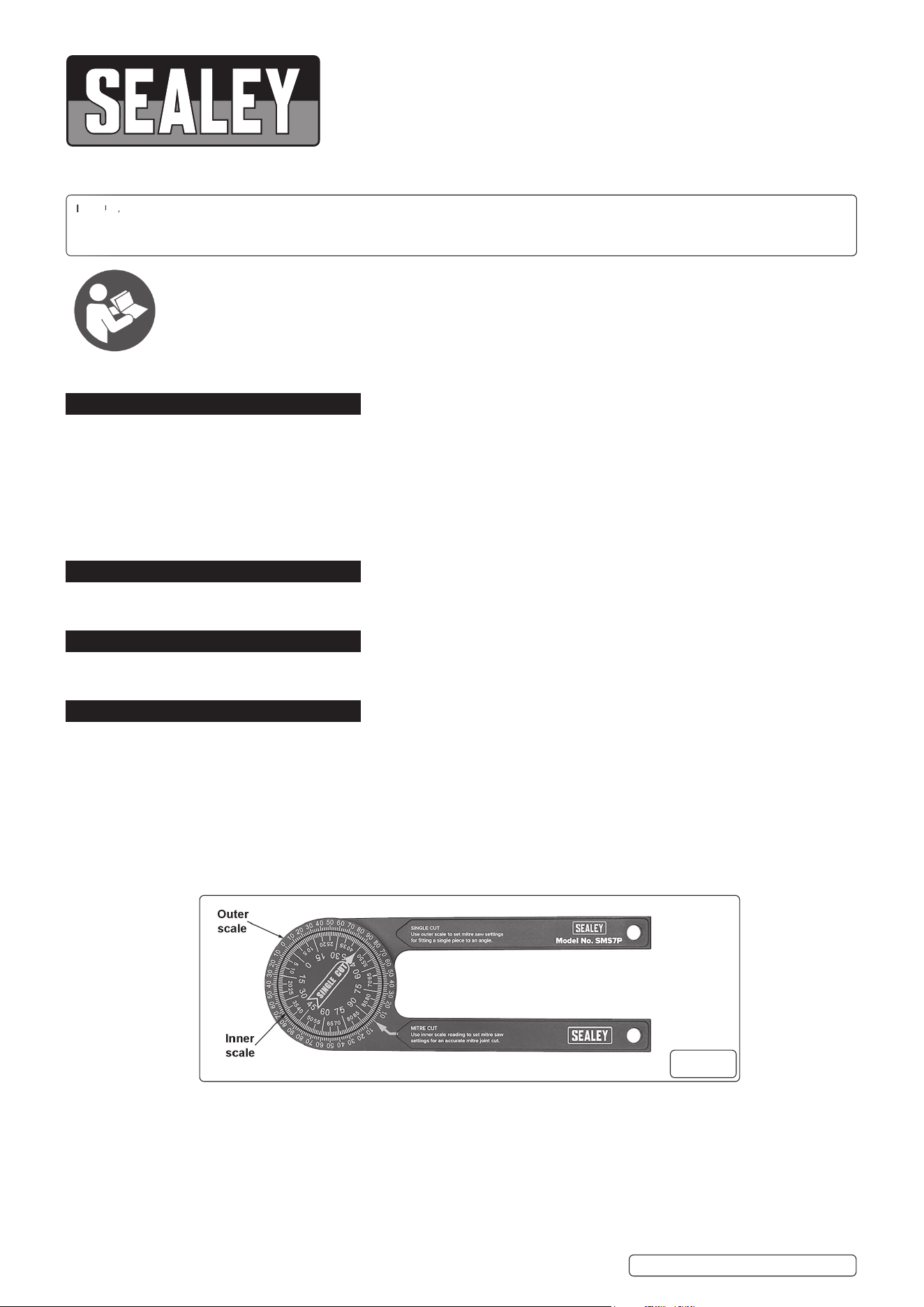
NOTE: The outer scale is used to set the mitre saw setting angle to allow the placement of a single work piece to fit to an angle.
4.1.1. Measure the corner angle at the required location.
4.1.2. Read the angle on the outer scale (fi g 1).
4.1.3. Set the mitre saw to this angle and cut work piece to suit.
4.2. MITRE CUT
NOTE: The inner scale reading is used to set the mitre saw setting angle to achieve accurate mitred joints.
4.2.1. Measure the corner angle at the required location.
4.2.2. Read the angle on the inner scale (fi g 1).
4.2.3. Set the mitre saw to this angle and cut work pieces to suit.
4.3. CROWN MOULDING CUT
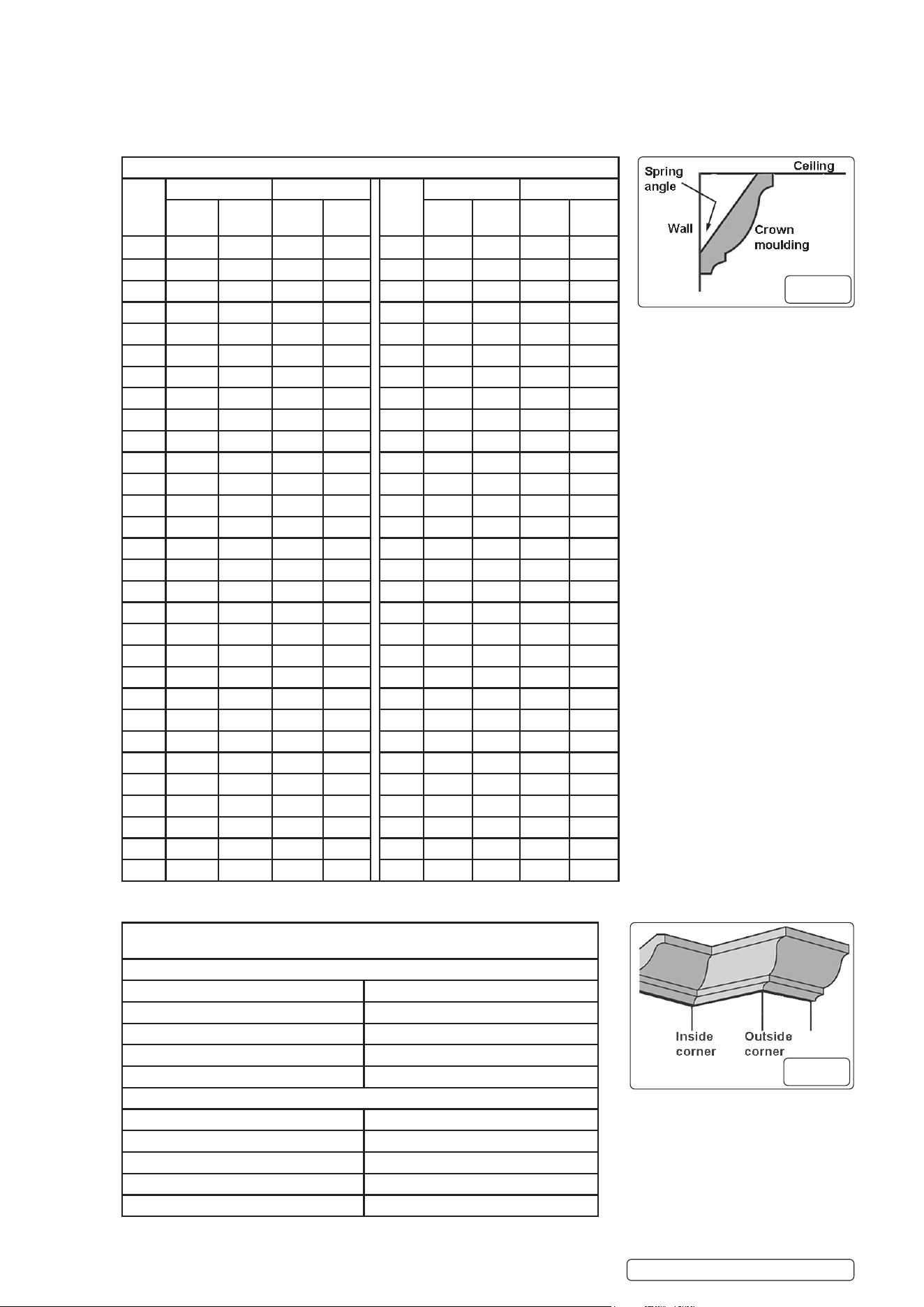
4.3.1. Place the mitre saw protractor onto the wall near to the ceiling and adjust to suit the inside or outside corner angle (fi g 3).
WARNING! If working at height take adequate safety precautions to prevent injury from falling.
4.3.2. Note the angle value on the inner scale (fi g 1).
4.3.3. Determine the spring angle (available on purchase of moulding) (fi g 2).
4.3.4. Refer to the Compound Cut Conversion Table, and locate the corresponding value from the inner scale on the mitre saw protractor,
with the row with the same “Mitre Cut” value.
4.3.5. Make a note of the “Mitre Angle” and the “Bevel Angle” from the corresponding row to suit the Crown angle of the work piece
(38º or 45º).
4.3.6. Set the mitre angle and the bevel angle on your compound mitre saw to suit.
SMS7P Issue 1 16/11/21
Original Language Version
© Jack Sealey Limited
Refer to
instructions
fi g.1
4.3.7. Refer to the Settings and Layouts for Cutting table and position the fi rst work piece as listed.
4.3.8. Place the fi rst work piece onto the compound mitre saw and perform the cut.
4.3.9. Refer to the Settings and Layouts for Cutting table to reset the compound mitre saw position for the second cut.
4.3.10. Place the second work piece onto the compound mitre saw and perform the cut.
WARNING! Read and understand the compound mitre saw instructions.
NOTE: Prior to cutting your work piece perform practice cuts on smaller scrap pieces.
SMS7P Issue 1 16/11/21
Original Language Version
© Jack Sealey Limited
COMPOUND CUT CONVERSION TABLE
Mitre
Cut
38º Crown 45º Crown Mitre
Cut
38º Crown 45º Crown
Mitre
Angle
Bevel
Angle
Mitre
Angle
Bevel
Angle
Mitre
Angle
Bevel
Angle
Mitre
Angle
Bevel
Angle
1 0.6 0.8 0.7 0.8 31 20.3 23.9 23.0 21.4
2 1.2 1.6 1.4 1.4 32 21.0 24.7 23.8 22.0
3 1.9 2.4 2.1 2.1 33 21.8 25.4 24.7 22.7
4 2.5 3.2 2.8 2.8 34 22.6 26.2 25.5 23.3
5 3.1 3.9 3.5 3.5 35 23.3 26.9 26.3 23.9
6 3.7 4.7 4.3 4.2 36 24.1 27.6 27.2 24.6
7 4.3 5.5 5.0 4.9 37 24.9 28.3 28.1 25.2
8 5.0 6.3 5.7 5.7 38 25.7 29.0 28.9 25.8
9 5.6 7.1 6.4 6.4 39 26.5 29.7 29.8 26.4
10 6.2 7.9 7.1 7.1 40 27.3 30.4 30.7 27.0
11 6.8 8.7 7.8 7.8 41 28.2 31.1 31.6 27.6
12 7.5 9.4 8.6 8.5 42 29.0 31.8 32.5 28.2
13 8.1 10.2 9.3 9.2 43 29.9 32.5 33.4 28.8
14 8.7 11.0 10.0 9.9 44 30.7 33.2 34.3 29.4
15 9.4 11.8 10.7 10.6 45 31.8 33.9 35.3 30.0
16 10.0 12.5 11.5 11.2 46 32.5 34.5 36.2 30.6
17 10.7 13.3 12.2 11.9 47 33.4 35.2 37.2 31.1
18 11.3 14.1 12.9 12.6 48 34.4 35.9 38.1 31.7
19 12.0 14.9 13.7 13.3 49 35.3 36.5 39.1 32.3
20 12.6 15.6 14.4 14.0 50
36.3 37.1 40.1 32.8
21 13.3 16.4 15.2 14.7 51 37.2 37.8 41.1 33.3
22 14.0 17.2 15.9 15.4 52 38.2 38.4 42.2 33.9
23 14.7 17.9 16.7 16.0 53 39.3 39.0 43.2 34.4
24 15.3 18.7 17.5 16.7 54 40.3 39.6 44.2 34.9
25 16.0 19.5 18.3 17.4 55 41.3 40.2 45.3 35.4
26 16.7 20.2 19.0 18.1 56 42.4 40.8 46.4 35.9
27 17.4 21.0 19.8 18.7 57 43.5 41.4 47.4 36.4
28 18.1 21.7 20.6 19.4 58 44.6 4.9 48.5 36.8
29 18.8 22.5 21.4 20.1 59 45.7 42.5 49.6 37.3
30 19.6 23.2 22.2 20.7 60 46.8 43 50.8 37.8
SETTINGS AND LAYOUT FOR CUTTING CROWN MOULDING WITH A
COMPOUND MITRE SAW
INSIDE CORNER
LEFT PIECE RIGHT PIECE
Mitre swing: RIGHT Mitre swing: LEFT
Bevel swing: LEFT Bevel swing: LEFT
Work piece location: LEFT of BLADE Work piece location: LEFT of BLADE
Moulding edge against fence: TOP Moulding edge against fence: BOTTOM
OUTSIDE CORNER
LEFT PIECE RIGHT PIECE
Mitre swing: LEFT Mitre swing: RIGHT
Bevel swing: RIGHT Bevel swing: RIGHT
Work piece location: RIGHT of BLADE Work piece location: RIGHT of BLADE
Moulding edge against fence: BOTTOM Moulding edge against fence: TOP
fi g.2
fi g.3

SMS7P Issue 1 16/11/21
Original Language Version
© Jack Sealey Limited
Sealey Group, Kempson Way, Suffolk Business Park, Bury St Edmunds, Suffolk. IP32 7AR
01284 757500 01284 703534 sales@sealey.co.uk www.sealey.co.uk
ENVIRONMENT PROTECTION
Recycle unwanted materials instead of disposing of them as waste. All tools, accessories and packaging should be sorted, taken to
a recycling centre and disposed of in a manner which is compatible with the environment. When the product becomes completely
unserviceable and requires disposal, drain any fluids (if applicable) into approved containers and dispose of the product and fluids
according to local regulations.
Note: It is our policy to continually improve products and as such we reserve the right to alter data, specifications and component parts without prior
notice.
Important: No Liability is accepted for incorrect use of this product.
Warranty: Guarantee is 12 months from purchase date, proof of which is required for any claim.
