
INSTRUCTIONS FOR
METAL CUTTING BANDSAW
MODEL NO: SM65.V2
Thank you for purchasing a Sealey product. Manufactured to a high standard, this product will, if used according to these instructions,
and properly maintained, give you years of trouble free performance.
IMPORTANT: PLEASE READ THESE INSTRUCTIONS CAREFULLY. NOTE THE SAFE OPERATIONAL REQUIREMENTS, WARNINGS & CAUTIONS. USE
THE PRODUCT CORRECTLY AND WITH CARE FOR THE PURPOSE FOR WHICH IT IS INTENDED. FAILURE TO DO SO MAY CAUSE DAMAGE AND/OR
PERSONAL INJURY AND WILL INVALIDATE THE WARRANTY. KEEP THESE INSTRUCTIONS SAFE FOR FUTURE USE.
1. SAFETY
1.1. ELECTRICAL SAFETY
WARNING! It is the user’s responsibility to check the following:
Check all electrical equipment and appliances to ensure that they are safe before using. Inspect power supply leads, plugs and all
electrical connections for wear and damage. Sealey recommend that an RCD (Residual Current Device) is used with all electrical
products. You may obtain an RCD by contacting your local Sealey dealer.
If the product is used in the course of business duties, it must be maintained in a safe condition and routinely PAT (Portable Appliance
Test) tested.
Electrical safety information: it is important that the following information is read and understood.
1.1.1. Ensure that the insulation on all cables and on the appliance is safe before connecting it to the power supply.
1.1.2. Regularly inspect power supply cables and plugs for wear or damage and check all connections to ensure that they are secure.
1.1.3. Important: Ensure that the voltage rating on the appliance suits the power supply to be used and that the plug is tted with the correct
fuse - see fuse rating in these instructions.
8 DO NOT pull or carry the appliance by the power cable.
8 DO NOT pull the plug from the socket by the cable.
8 DO NOT use worn or damaged cables, plugs or connectors. Ensure that any faulty item is repaired or
replaced immediately by a qualied electrician.
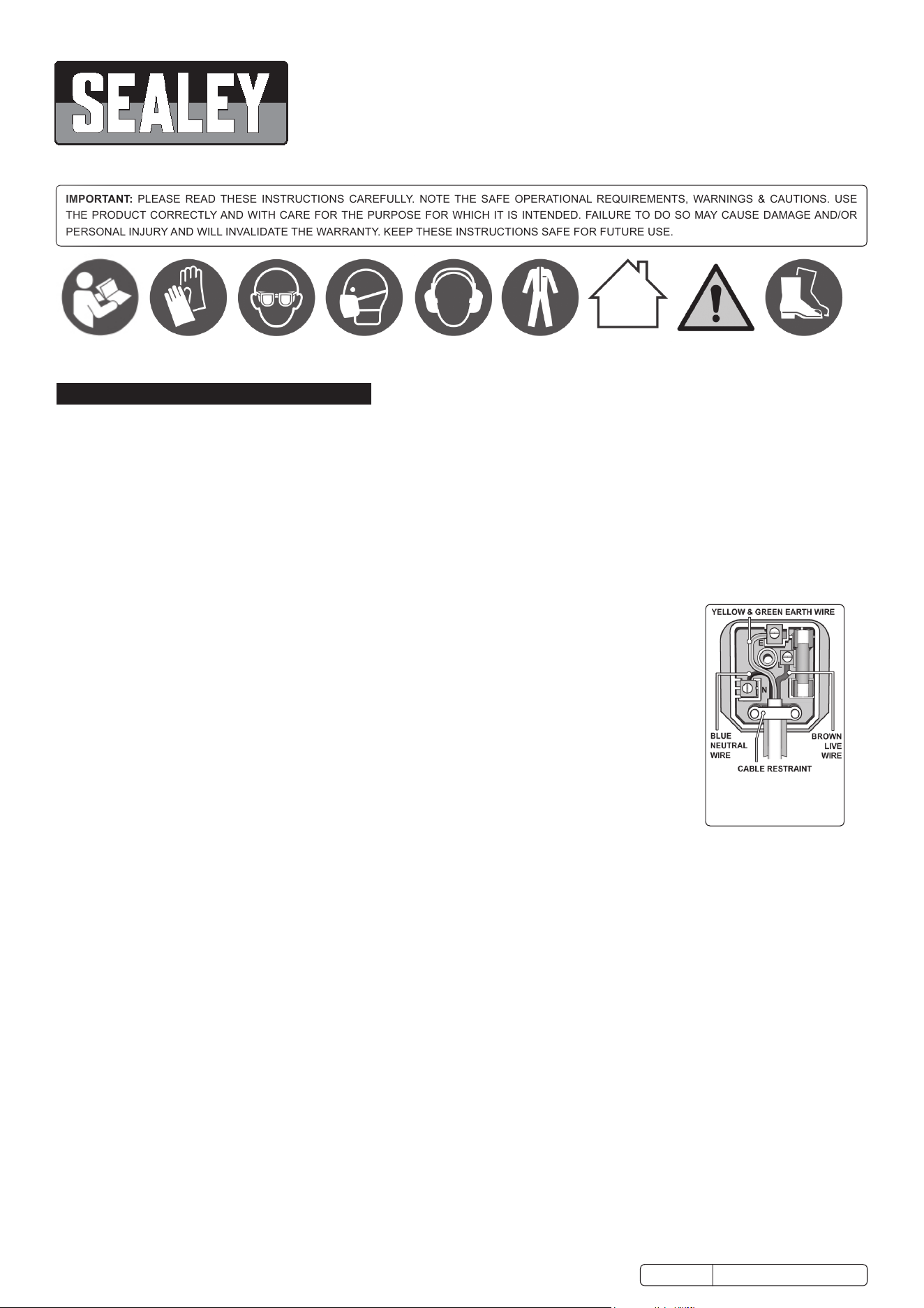
1.1.4. This product is tted with a BS1363/A 13 Amp 3 pin plug.
If the cable or plug is damaged during use, switch the electricity supply and remove from use.
Ensure that repairs are carried out by a qualied electrician.
Replace a damaged plug with a BS1363/A 13 Amp 3 pin plug. If in doubt contact a qualied electrician.
A) Connect the GREEN/YELLOW earth wire to the earth terminal ‘E’.
B) Connect the BROWN live wire to the live terminal ‘L’.
C) Connect the BLUE neutral wire to the neutral terminal ‘N’.
Ensure that the cable outer sheath extends inside the cable restraint and that the restraint is tight.
Sealey recommend that repairs are carried out by a qualied electrician.
1.1.5. If an extension reel is used it should be fully unwound before connection. A reel with an RCD fitted is
preferred since any appliance plugged into it will be protected. The cable core section is important and should be at least 1.5mm², but
to be absolutely sure that the capacity of the reel is suitable for this product and for others which may be used in the other output sockets,
we recommend the use of 2.5mm² section cable. If extension reel is to be used outdoors, ensure it is marked for outdoor use.
1.2. GENERAL SAFETY
WARNING! Disconnect the bandsaw from the power source before servicing, changing accessories or performing any other maintenance.
9 Familiarise yourself with applications and limitations of the product, as well as the potential hazards.
9 Maintain the bandsaw in good condition. Keep it clean and keep blades sharp for best and safest performance.
9 Use original Sealey spare parts only. Unapproved parts may be dangerous and will invalidate the warranty.
9 Keep all guards and fixing screws in place, tight and in working order. Check regularly for damaged parts. A guard or any other part
that is damaged must be repaired or replaced before the saw is used further. Check also the alignment of moving parts, loose mountings,
or any other condition that could affect the operation of the saw.
9 Ensure that the space allocated for use and maintenance of the machine is adequate, free from unrelated materials and has good lighting.
9 Remove any adjusting keys and wrenches from the machine before operating.
9 Wear approved eye and ear protection when operating the machine. If dust is produced, wear an approved face or dust mask.
9 Keep correct footing and balance at all times and wear non-slip shoes with protective toe caps.
9 Always secure the workpiece with a clamp or vice.
9 Keep children and unauthorised persons away from the work area, especially when the saw is in operation.
9 Ensure that large or oversize workpieces are supported at table height. Ensure you use a suitable support for any workpiece that does
not have a flat surface. Be cautious when cutting workpieces which are irregular in cross-section. The saw blade could be pinched before
the cut is completed. Any stock such as frame moulding, must lay flat on the table surface and not be allowed to rock.
WARNING! Rods and tubing have a tendency to roll while being cut, causing the blade to “bite”. DO NOT cut such items without
first clamping or blocking the workpiece.
WARNING! Never force the blade through the workpiece.
8 DO NOT use this machine for anything other than its intended purpose. The machine is designed for light metal cutting work in engineering
workshops, garages, metal fabricators, etc.
Replacement fuse
rating: 5 AMP
Original Language Version
© Jack Sealey Limited
Refer to
instruction
manual
Wear protective
gloves
Wear eye
protection
Wear face
mask
Wear ear
protection
Wear protective
clothing
SM65.V2 Issue 4 (H, F) 06/02/18
Indoor use only Warning Wear
protective
footwear
WARNING! The SM65.V2 bandsaw MUST NOT be used to cut non-metallic materials (including wood) as to do so will invalidate your
insurance cover and your warranty and may cause damage and/or personal injury.
8 DO NOT wear loose or ill-fitting clothing. Remove ties, watches, rings and other jewellery. Tie up, or adequately cover, long hair.
8 DO NOT start the machine until the workpiece is secure and the blade has been lowered to just above the workpiece.
8 DO NOT use the bandsaw with the blade guard or pulley cover removed.
8 DO NOT use damaged or deformed blades.
9 Turn the saw off before raising the blade.
8 DO NOT run the saw with the blade in the raised position.
8 DO NOT use the machine in wet or damp locations.
8 DO NOT use the machine in areas where fumes from paint, solvents, or flammable liquids pose a potential hazard. Keep all flammable
materials (including wipers or cleaning rags) away from the saw, and dispose of according to local regulations.
8 DO NOT stand on the machine.
8 DO NOT leave machine running unattended. Turn power switch ‘Off’ and DO NOT leave area until machine has come to a complete stop.
8 DO NOT use whilst under the influence of drugs, alcohol or other intoxicating medication. DO NOT use the tool if you are tired.
2. iiiINTRODUCTION
Fully guarded blade with magnetic no-load voltage switch to prevent motor re-start in the event of power failure or blade jam. Fitted
with oil-bath gearbox and life lubricated drive bearings for quiet, smooth operation. Features swivel arm facility to aid angle cutting of
long pieces of stock in confined workshop. Supplied with quick action vice - push the jaw up to the workpiece and then pull the cam
action lever to lock. Fully adjustable precision blade guides for accurate cutting and longer blade life. Supplied with anti-vibration feet and
workshop stand.
3. i SPECIFICATION
Model no:.: .............................................................. SM65.V2
Capacity 90
o
- Round: ..........................................Dia. 105mm
Capacity 90
o
- Square / Rectangular (H x W):....105 x 150mm
Capacity 45
o
- Round: ..........................................Dia. 100mm
Capacity 45
o
- Square / Rectangular (H x W):....... 85 x 65mm
Blade Size: ............................................ 1638 x 13 x 0.63mm
Blade Speeds: ............................................ 18, 30, 48mtr/min
Motor Power: ................................................................. 375W
Supply: ...........................................................................230V
Weight: ........................................................................... 60kg
4. ASSEMBLY
4.1. ASSEMBLY
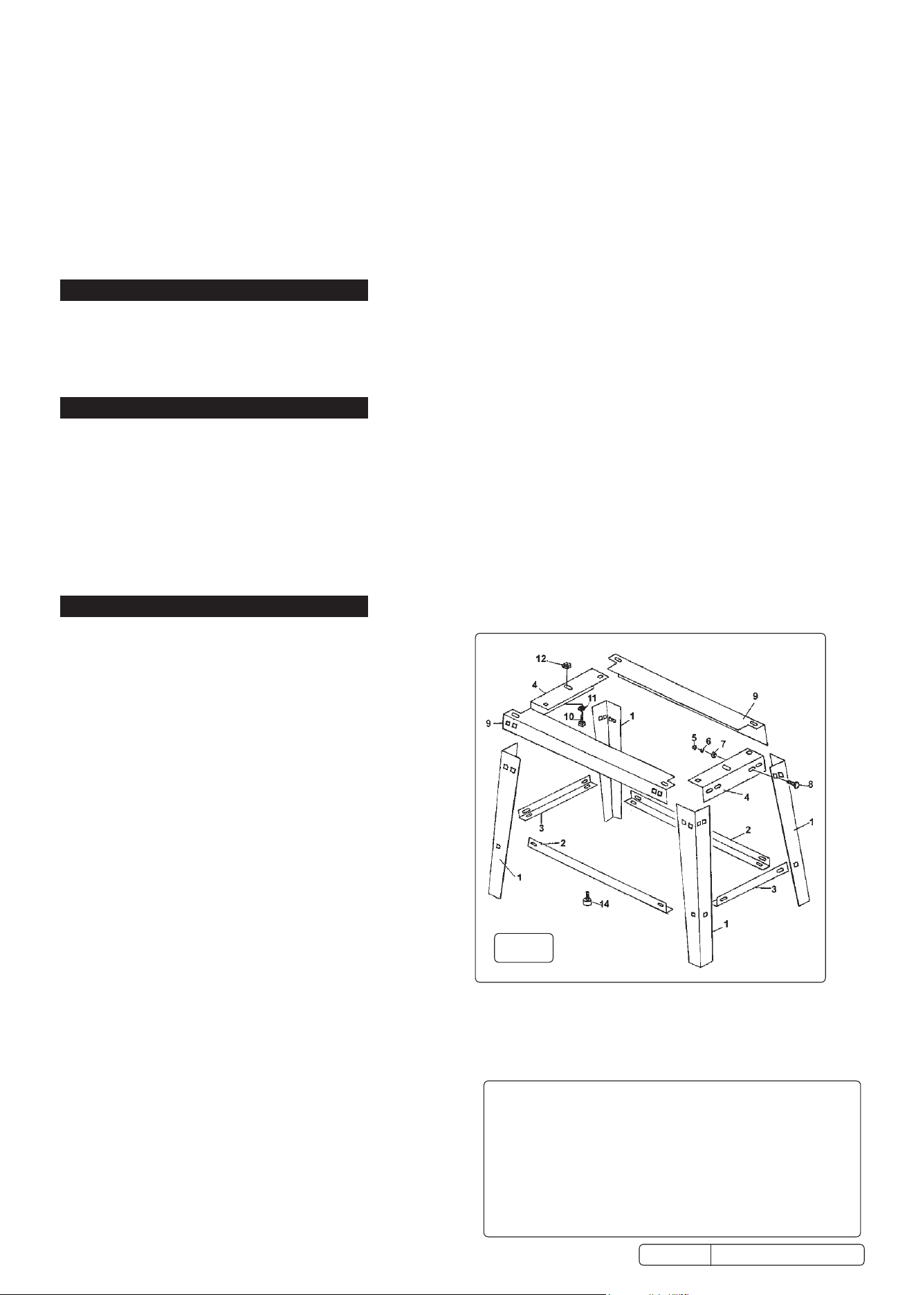
NOTE: Numbered brackets refer to Fig 1 and Parts diagram.
4.1.1. Assemble the floor stand as described below using the nuts
and bolts provided (refer to Fig 1).
4.1.2. Make one end frame by assembling two legs (1) to short
upper cross member (4) using four bolts (8), four washers (7),
four split washers (6) and four nuts (5). Attach lower short
cross member (3) to the inside of the legs using two bolts (8).
4.1.3. Create a second end frame using the same set of components.
Join the two end frames together using two long upper cross
members (9) using two bolts (8) at each end of each cross
member. The ends of the long cross members should pass under
the ends of the short cross members (4).
4.1.4. Attach the two lower long cross members (2) to the inside of
the frame using one bolt at the end of each.
4.1.5. The anti-vibration mountings (14) can either be fitted to the base
of the saw or to the stand. For bench mounting and when the
stand is to be secured to the floor, fit the mountings to the saw
base. Where the stand is to be portable, fit the mountings to
the bottom of the legs.
4.1.6. Place the saw onto the stand and retain it at either end with
bolt (10), washer (11) and nut (12).
4.1.7. Remove transit chain (15), retain for future use.
4.1.8. Slide fence (104) into vice base (103) and tighten set screw in front face of vice to retain.
4.1.9. When the saw arm is in the down position the cutting edge of the blade should be just below the main surface of the vice in order for
the blade to cut all the way through the workpiece. If this is not the case, loosen the lock nut (37) and adjust the stop bolt (38) so that
the cutting edge of the blade is 2 to 3mm below the vice surface. Re-tighten locknut (37).
4.1.10. Adjust switch cut-off screw (17) to ensure that ‘Off’ switch is actuated when, or just before, the body frame contacts the abutment
screw (38). Tighten nut (5).
4.2. BLADE SELECTION
The chart at the right show the recommended setup for various
metals and cut lengths. Blades are available from your Sealey
stockist in four tooth pitches: 6, 10, 14 and 24 tpi (see parts list).
fig.
1
Blade Chart for Flat and Round Bar
Recommended blade teeth per inch (tpi) for nominal cut length.
Cut Length Under 8mm 4-13mm 6-16mm 8-22mm
Tpi 32 24 18 14
Cut Length 10-35mm 17-40mm 25-50mm 38-75mm
Tpi 10 8 6 4
Cut Length 50-100mm 75-150mm 114-225mm >200mm
Tpi 3 2 1.25 0.75
SM65.V2 Issue 4 (H, F) 06/02/18
Original Language Version
© Jack Sealey Limited
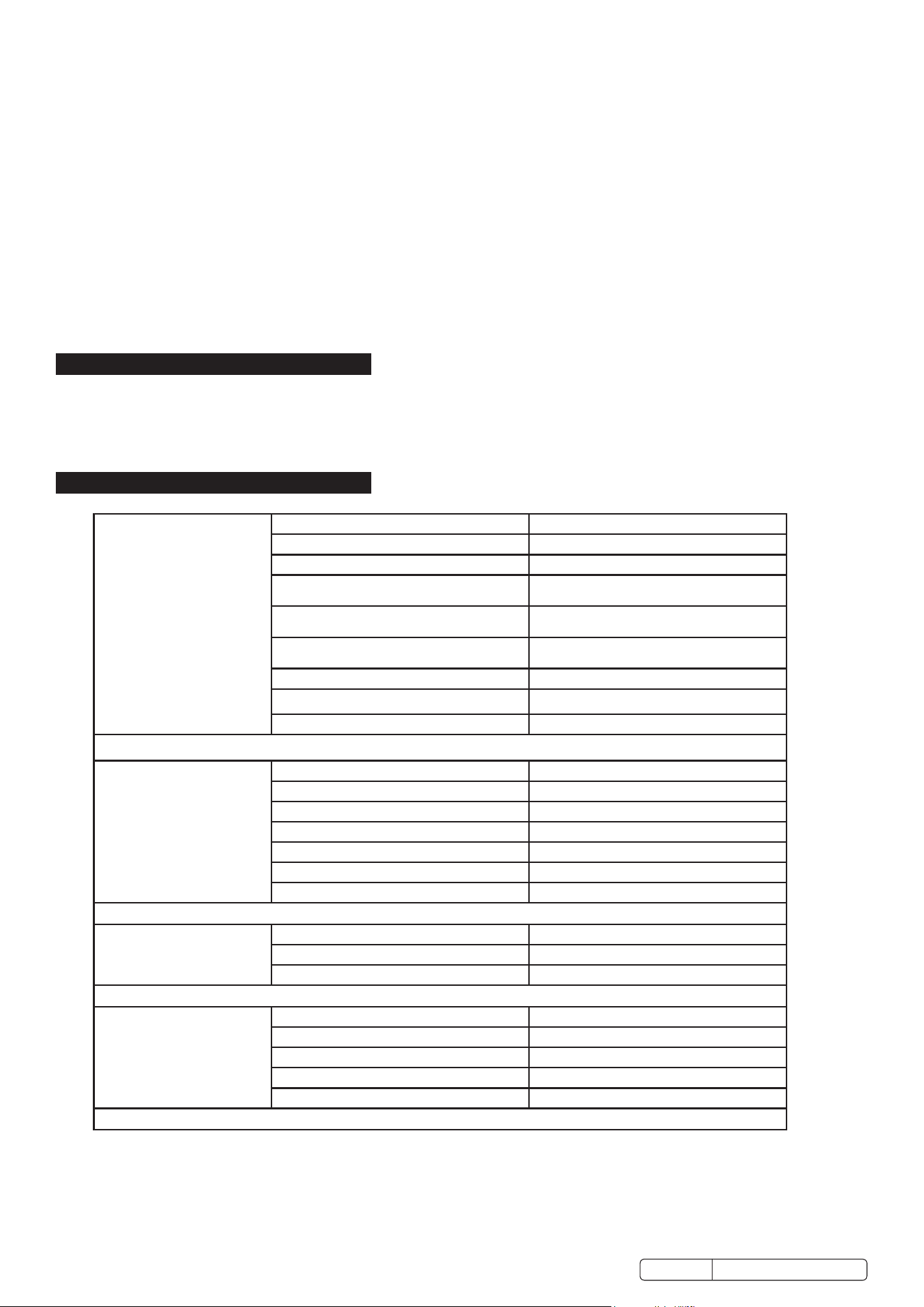
4.3. ADJUSTING BLADE SPEED
Adjust the blade speed to suit the metal to be cut. The
recommended pulley selections are shown in the chart to
the right.
4.3.1. Disconnect saw from power supply and open the pulley
cover (52).
4.3.2. Loosen the motor securing nuts (12) on the motor plate
to slacken the belt.
4.3.3. Move the belt to the required pulley grooves (see chart).
4.3.4. Tension belt and tighten nuts (12), close and secure the
pulley cover using screw (30) and washer (7).
5. OPERATION
WARNING! Before operating the bandsaw ensure that you read, understand and apply the safety instructions in Section 1.
NOTE: Before operating the machine certain checks and adjustments will need to be carried out. It is very important that
these instructions are followed carefully in order that the machine is set up safely and correctly.
WARNING! The machine is designed for the cutting of light metal in engineering workshops, garages, metal fabricators, etc.
The SM65.V2 must not be used to cut any other materials (including wood). To do so will invalidate your insurance cover and your
warranty and may cause damage and/or personal injury.
NOTE: The harder the material being cut, the slower the cutting speed should be. The use of a cutting oil is recommended with the
higher blade speeds.
5.1. HORIZONTAL CUTTING
WARNING! BEFORE MAKING ANY ADJUSTMENTS, DISCONNECT SAW FROM POWER SUPPLY.
5.1.1. Adjust the blade speed to suit the workpiece (see section 4.3).
5.1.2. Raise the saw arm as far as possible.
5.1.3. Adjust the stock stop rod (104) to the desired length.
5.1.4. Raise the handle of quick grip vice (103) to unlock and slide back vice jaw. Insert workpiece against fixed jaw. Slide vice jaw up to
workpiece and firmly press down vice handle to clamp it securely.
5.1.5. If an angled cut is required slacken lever nut (36). Rotate bevel holder (31) and saw arm to angle required and tighten lever nut (36).
5.1.6. Adjust the two blade guides, by slackening the knob (99) and the screw (43), so that they are close to the workpiece but will not foul it.
Gently lower the arm until the blade is just above the workpiece. Connect the saw to the power supply and start the saw.
DO NOT turn on the machine until the workpiece is secured and the blade has been lowered to just above workpiece.
5.1.7. Bring the blade into contact with the workpiece and then release the arm. If the blade jams and the saw does not automatically shut
off, immediately disconnect it from the power supply. Refer to the ‘Troubleshooting’ section for common problems.
5.1.8. When sawing is completed disconnect from the power supply, raise blade and remove workpiece.
WARNING! NEVER RAISE THE BLADE WHEN THE MACHINE IS RUNNING AND NEVER RUN THE MACHINE WHEN THE BLADE
IS RAISED.
6. ADJUSTMENTS
WARNING! BEFORE MAKING ANY ADJUSTMENTS, DISCONNECT SAW FROM POWER SUPPLY.
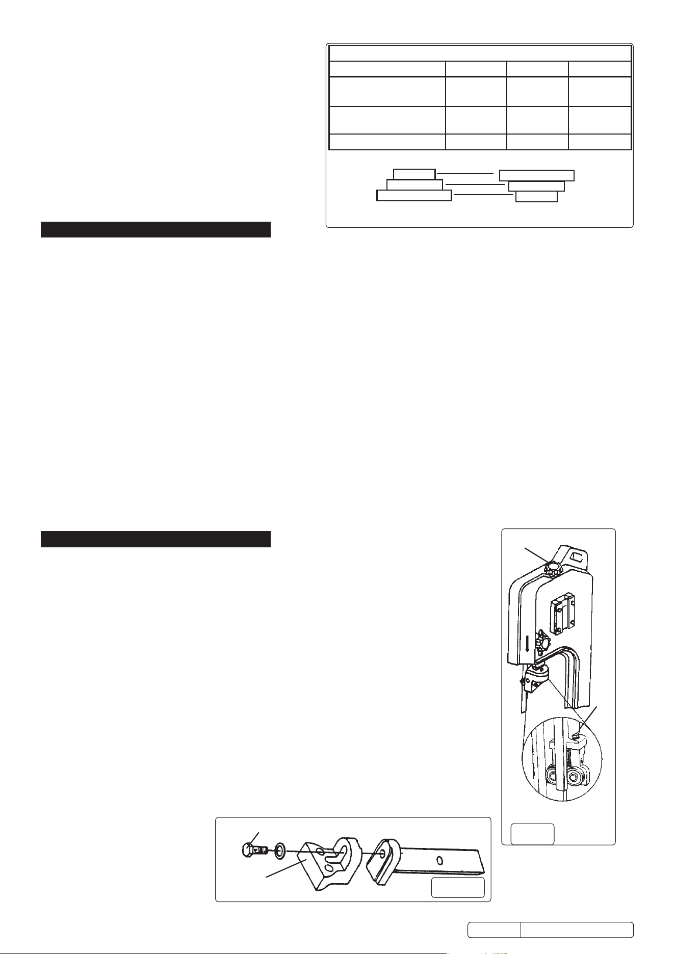
6.1. BLADE TENSION
6.1.1. Disconnect the machine from the power supply and then remove blade cover.
6.1.2. ` Adjust the blade tension with knob (95) (fig.2.A), so that light thumb pressure on the blade midway
between the blade wheels produces a deflection of approximately 1mm. DO NOT over tighten.
6.1.3. Replace blade cover, reconnect to power source and run for two to three minutes to seat the blade.
6.1.4. Disconnect saw from the power source, remove blade cover and recheck tension. Replace blade cover.
6.2. BLADE GUIDE BEARING ADJUSTMENT
6.2.1. Correct guide bearing (fig.2.B) adjustment is important so that the blade runs smoothly and evenly
without twisting or snagging anywhere. Each of the outer guide bearings is mounted on an adjustable
eccentric bush.
6.2.2. Disconnect the machine from the power supply.
6.2.3. Loosen the bearing pivot (59) lock nut (12) while holding the pivot, immediately above the bearing, with
an open ended spanner.
6.2.4. Turn the pivot to adjust the bearing. The bearing should barely touch the blade (0.001” clearance).
6.2.5. Tighten the lock nut when satisfied with the bearing adjustment.
6.2.6. Adjust both outer guide bearings.
6.2.7. When satisfied that the adjustment is accurate, carefully turn the blade wheels by hand to see if the
blade snags or rubs at any point. Readjust bearing(s) if necessary.
6.3. BLADE GUIDE ADJUSTMENT
6.3.1. Disconnect the machine from the power supply.
6.3.2. Loosen hex bolt (fig.3.E) and pivot blade adjustment bracket (fig.3.F) until blade is perpendicular to
vice bed (103).
6.3.3. Retighten the hex bolt (fig.3.E).
B
A
E
fig.
2
fig. 3
Original Language Version
© Jack Sealey Limited
Recommended Pulley Selection for Various Metals
Material Motor Pulley Blade Pulley Blade Speed
Tool, stainless or alloy
steel. Bearing bronze.
Small (A) Large (D) 20m/min
Low to medium carbon
steel
Medium (B) Medium (E) 29m/min
Aluminium, Copper, Brass Large (D) Small (F) 50m/min
B
A
C
Motor Pulley
F
E
D
Blade Pulley
SM65.V2 Issue 4 (H, F) 06/02/18
6.4. REPLACING THE SAW BLADE
6.4.1. We recommend you keep a small supply of commonly used saw blades to hand. Change saw blades frequently for best results. Ensure
you choose a blade with a pitch suitable for workpiece to be cut (see cutting chart, Section 4).
WARNING! TAKE CARE WHEN HANDLING SAW BLADES, BLADE TEETH ARE VERY SHARP.
6.4.2. Loosen the blade tension, move both front guide bearings away from blade (see para. 6.2.) and remove blade cover.
6.4.3. Carefully remove old blade and install new one ensuring that tooth direction is consistent with the blade travelling left-to-right in the cutting
area.
6.4.4. Reset blade tension (see para. 6.1.), check tracking (see para. 6.5.), replace blade cover and adjust guide bearings (see para. 6.2.).
6.5. BLADE TRACKING
6.5.1. Adjustment of the blade tracking is necessary to prevent the blade from twisting or coming off the blade wheels. This adjustment
should be made whenever a new blade is fitted (see para. 6.4.).
6.5.2. Run saw for a short time and then switch off.
6.5.3. Raise saw arm, remove blade cover and check blade-to-wheel relationship (tracking). Rear edge of blade should be very close to, but
not hard against, the wheel anges.
6.5.4. If inspection indicates that adjustment is required reduce blade tension (see para. 6.1.) and loosen the screw (65) in driven wheel (67).
6.5.5. Move drive wheel in or out on shaft as required to improve tracking and tighten set screw.
6.5.6. Having made a small adjustment, tension blade, replace the blade cover, lower the arm and run the saw for a short time.
6.5.7. Switch saw off, remove blade cover and check tracking. Repeat adjustment procedure if necessary.
7. MAINTENANCE
7.1. Clean saw after each operation and smear unpainted surfaces with oil to prevent rusting.
7.2. Annually replace gearbox oil (SAE 90) as follows:
7.2.1. With blade arm horizontal remove gearbox cover screws (16), cover (78) and gasket (77).
7.2.2. Place oil container under right hand lower corner of gearbox and then carefully raise saw arm fully to drain oil.
7.2.3. Lower saw arm, remove any remaining oil from gearbox with clean cloths and then refill with fresh oil. Replace cover and gasket.
8. TROUBLESHOOTING
Excessive blade breakage and/or
teeth ripping from the blade.
1. Workpiece is loose in the vice. 1. Clamp the workpiece securely.
2. Incorrect speed or feed. 2. Adjust the speed or feed to suit the workpiece.
3. Blade is too fine. 3. Replace with a coarser blade.
4. Workpiece is too course. 4. Use the saw at slower speed and use a smaller
tpi blade.
5. Incorrect blade tension. 5. Adjust blade tension so that it does not slip on
the wheel.
6. Blade is in contact with workpiece before saw
is started.
6. Place blade in contact with the workpiece
only after the saw has started.
7. Blade is rubbing on the wheel flange. 7. Adjust blade wheel alignment.
8. Blade guides are misaligned. 8. Adjust blade guide alignment.
9. Blade is too thick. 9. Use correct thickness blade.
Premature blade dulling. 1. Blade tpi is too high. 1. Replace with a smaller tpi blade.
2. Incorrect speed - too fast. 2. Reduce speed.
3. Inadequate feed pressure. 3. Increase feed pressure.
4. Hard spots or scale on the workpiece. 4. Reduce speed, increase feed pressure.
5. Blade is twisting. 5. Replace blade and adjust to the correct tension.
6. Insufficient blade tension. 6. Increase blade tension.
7. Blade is slipping. 7. Increase blade tension and reduce speed.
Unusual wear on side or back of
blade.
1. Blade guides are worn. 1. Replace blade guides.
2. Blade guides are misaligned. 2. Adjust guide pivots.
3. Blade guide brackets are loose. 3. Tighten blade guide brackets.
Motor overheating. 1. Blade tension too high. 1. Reduce blade tension.
2. Drive belt tension too high. 2. Reduce drive belt tension.
3. Blade too coarse or too fine. 3. Use a blade more suitable for the workpiece.
4. Gears need lubrication. 4. Lubricate the gears.
5. Blade is binding in the cut. 5. Decrease feed and speed.
Original Language Version© Jack Sealey Limited
SM65.V2 Issue 4 (H, F) 06/02/18

Sealey Group, Kempson Way, Suffolk Business Park, Bury St Edmunds, Suffolk. IP32 7AR
01284 757500 01284 703534 sales@sealey.co.uk www.sealey.co.uk
ENVIRONMENT PROTECTION
Recycle unwanted materials instead of disposing of them as waste. All tools, accessories and packaging should be sorted, taken to
a recycling centre and disposed of in a manner which is compatible with the environment. When the product becomes completely
unserviceable and requires disposal, drain any fluids (if applicable) into approved containers and dispose of the product and fluids
according to local regulations.
Note: It is our policy to continually improve products and as such we reserve the right to alter data, specifications and component parts without prior
notice.
Important: No Liability is accepted for incorrect use of this product.
Warranty: Guarantee is 12 months from purchase date, proof of which is required for any claim.
Bad, crooked or rough cuts. 1. Feed pressure too great. 1. Reduce feed pressure.
2. Blade guides are misaligned. 2. Adjust blade guides.
3. Inadequate blade tension. 3. Increase blade tension.
4. Blade is dull. 4. Replace the blade.
5. Incorrect speed. 5. Adjust the speed.
6. Blade guides are spaced out too far. 6. Adjust guide spacing.
7. Blade guide assembly is loose. 7. Tighten the guide assembly.
8. Blade is too coarse. 8. Use a finer blade.
Blade is twisting. 1. Blade is binding in the cut. 1. Reduce feed pressure.
2. Blade tension is too high. 2. Decrease blade tension.
SM65.V2 Issue 4 (H, F) 06/02/18
Original Language Version
© Jack Sealey Limited