Loading ...
Loading ...
Loading ...
39
English
Installation Procedure
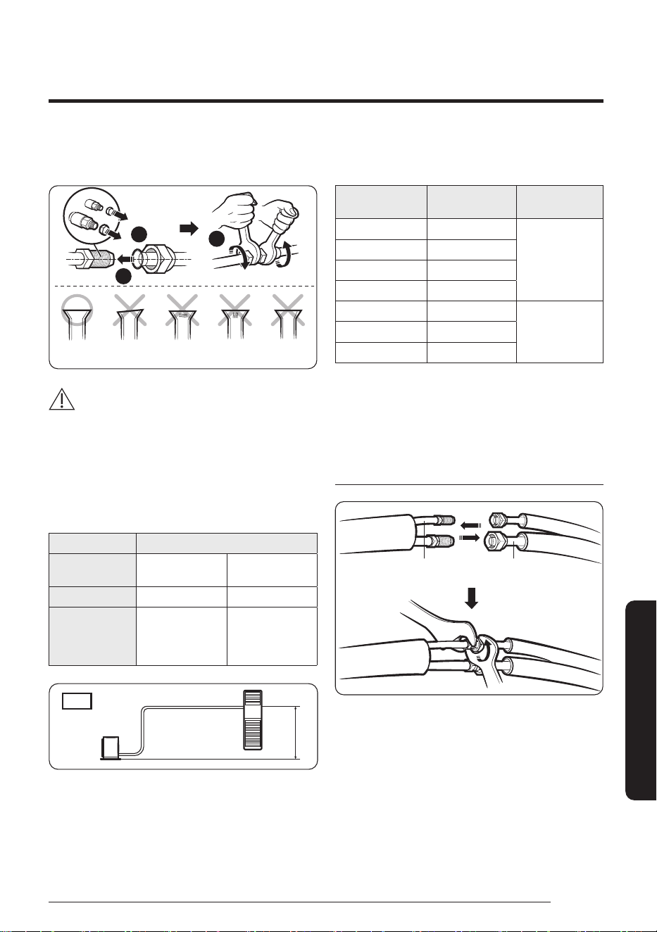
5 Check that the flaring is correct, referring to the
illustrations below for examples of incorrect flaring.
2
1
3
Correct Inclined Damaged
surface
Cracked
Uneven
thickness
CAUTION
• If the pipes require brazing ensure that OFN (Oxygen
Free Nitrogen) is flowing through the system.
• Nitrogen blowing pressure range is 0.02 to 0.05 MPa.
Step 8 Connecting the refrigerant
pipes
Items Maximum allowable length [m]
Outdoor unit
models
AC030BXPDKC
AC036BXPDKC
AC
048BXPD*C
AC054BXPDNC
Main pipe (L1) 50 75
Max. height
difference between
outdoor and indoor
unit (h1)
30 30
n=1
Outdoor
L₁
indoor
h₁
• Temper grade and minimum thickness of the
refrigerant pipe
Outer diameter [mm]
Minimum thickness
[mm]
Temper grade
ø6.35 0.7
C1220T-O
ø9.52 0.7
ø12.70 0.8
ø15.88 1.0
ø15.88 0.8
C1220T-1/2H OR
C1220T-H
ø19.05 0.9
ø22.23 0.9
1 Connect each assembly pipe to the appropriate valves on
the indoor and outdoor units and fasten the flare nuts.
2 As depicted in the illustration below, tighten the flare
nut manually, and then apply the following torque with a
torque wrench.
Indoor unit
Liquid side
service valve
Gas side
service valve
DB68-11731A-02_IBIM_PAC Mirage Cooling Only_TC_EN_.indd 39DB68-11731A-02_IBIM_PAC Mirage Cooling Only_TC_EN_.indd 39 2023-07-19 오전 9:52:162023-07-19 오전 9:52:16
Loading ...
Loading ...
Loading ...