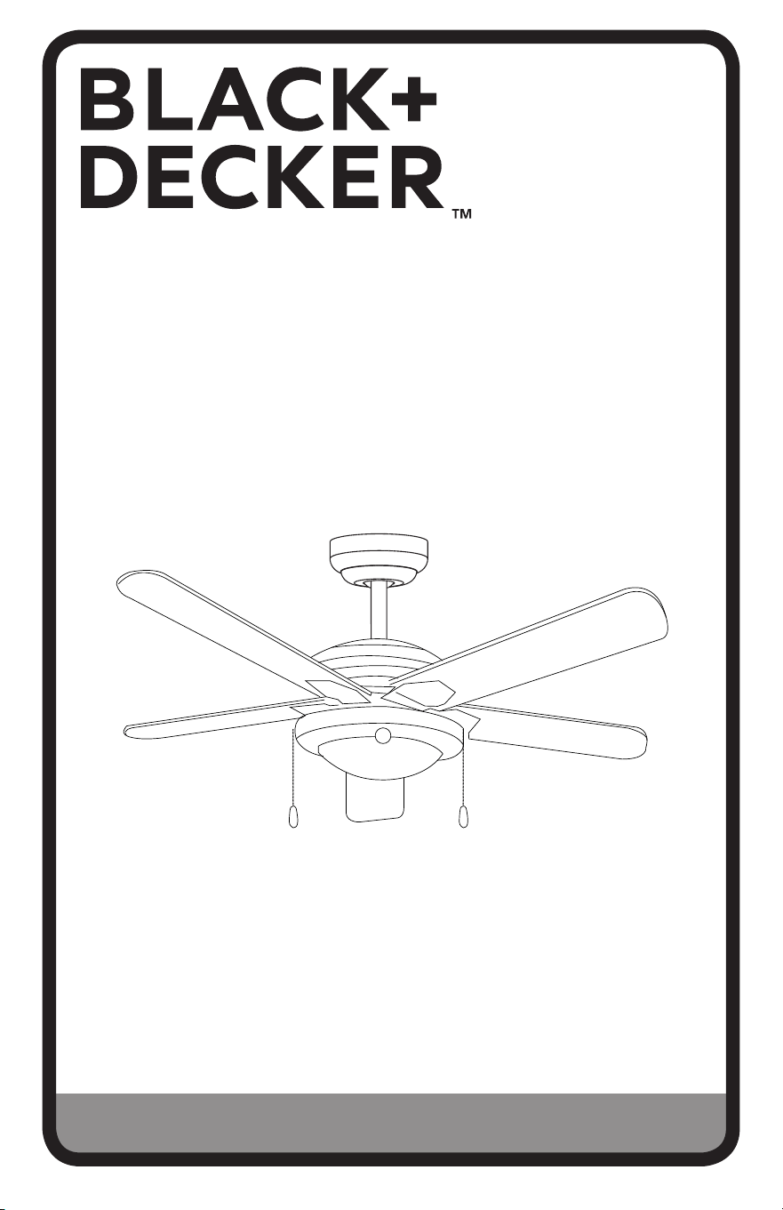
INSTRUCTION MANUAL
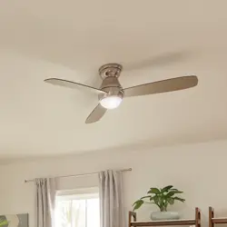
52 IN. CEILING FAN
Thank you for choosing BLACK+DECKER!
PLEASE READ BEFORE RETURNING THIS PRODUCT FOR
ANY REASON.
If you have a question or experience a problem with your BLACK+DECKER
purchase, go to www.blackanddecker.com/instantanswers
If you can’t find the answer or do not have access to the Internet, call
844-299-0879 from 10:30 a.m. to 6:30 p.m. EST Mon. - Fri. to speak with an
agent. Please have the catalog number available when you call.
SAVE THIS MANUAL FOR FUTURE REFERENCE.
CATALOG NUMBER
BCF5211
BCF5211R

Page 2
Thank you for purchasing our
BLACK+DECKER product. This
easy-to-use manual will guide you
in getting the best use of your fan.
Remember to record the model and
serial numbers. They are on a label
on the rear.
Staple your receipt to your manual.
You will need it to obtain warranty service.
Model number
Serial number
Date of purchase
PRODUCT REGISTRATION
CONTENTS
SAFETY INFORMATION
Important Safety Instructions ..........................................................................................................................................3-4
Handling Alkaline Batteries ...................................................................................................................................................5
SET UP & USE
Parts ............................................................................................................................................................................................. 6-7
Features ......................................................................................................................................................................................... 8
Preparing for Installation ........................................................................................................................................9
Mounting Bracket Installation .........................................................................................................................10-11
Mounting Fan to Ceiling ...................................................................................................................................12-14
Wiring Options ................................................................................................................................................... 15-16
Securing Fan to Ceiling .......................................................................................................................................... 17
Blade Installation ......................................................................................................................................................18
Light Fixture Installation ........................................................................................................................................19
Remote Control Operation ............................................................................................................................20-21
Operation ..................................................................................................................................................................22
Cleaning + Maintenance........................................................................................................................................23
TROUBLE SHOOTING & WARRANTY
Before You Call For Service ..............................................................................................................................24
Customer Service ..................................................................................................................................................24
Troubleshooting .....................................................................................................................................................25
Limited Warranty .................................................................................................................................................................. 26
Page 3
SAFETY INFORMATION
IMPORTANT SAFETY INSTRUCTIONS
1. READ ALL INSTRUCTIONS BEFORE USE
2. Installation work and electrical wiring must be done by qualified
person(s) in accordance with all applicable codes and standards,
including fire-rated construction.
3. Use this unit only in the manner intended by the manufacturer. If you
have any questions contact the manufacturer.
4. After making the wire connections, gently push connections into
outlet box with wire nuts pointing up. The wires should be spread
apart with the grounded conductor and the equipment grounding
conductor on one side of the outlet box and ungrounded conductor
on the other side of the outlet box.
5. Before you begin installing the fan, Switch power o at Service panel
and lock service disconnecting means to prevent power from being
switched on accidentally. When the service disconnecting means
cannot be locked, securely fasten a prominent warning device, such
as a tag, to the service panel.
6. Be cautious! Read all instructions and safety information before
installing your new fan. Review the accompanying assembly
diagrams.
7. When cutting or drilling into wall or ceiling, do not damage electrical
wiring and other hidden utilities.
8. Make sure the installation site you choose allows the fan blades to
rotate without any obstructions. Allow a minimum clearance of 7 feet
(2.1 meters) from the floor to the trailing edge of the blade.
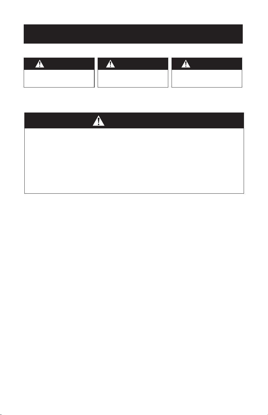
WARNING
WARNING - Hazards or unsafe
practices which COULD result in
severe personal injury or death
DANGER
DANGER - Immediate hazards
which WILL result in severe
personal injury or death
CAUTION
CAUTION - Hazards or unsafe
practices which COULD result in
minor personal injury
WARNING
TO REDUCE THE RISK OF FIRE, ELECTRIC SHOCK, OR PERSONAL INJURY, MOUNT
TO OUTLET BOX MARKED “ACCEPTABLE FOR FAN SUPPORT OF 35 LBS (15.9
KG) OR LESS” AND USE MOUNTING SCREWS PROVIDED WITH THE OUTLET
BOX AND/OR SUPPORT DIRECTLY FROM BUILDING STRUCTURE. MOST OUTLET
BOXES COMMONLY USED FOR THE SUPPORT OF LUMINARIES
ARE NOT ACCEPTABLE FOR FAN SUPPORT AND MAY NEED TO BE REPLACED.
CONSULT A QUALIFIED ELECTRICIAN IF IN DOUBT.
Page 4
SAFETY INFORMATION
9. To reduce the risk of fire, electric shock, or personal injury, this fan
must be mounted to an outlet box marked suitable for fan support.
And use mounting screws provided with the outlet box. (Mounting
must support at least 35 lbs. (15.9 kg)
10. WARNING: TO REDUCE THE RISK OF PERSONAL INJURY Do not
bend blade holders during installation to motor, balancing or during
cleaning. Do not insert foreign object between rotating blades.
11. Attach the mounting bracket using only the hardware supplied with
the outlet box. Fan is only to be mounted to an outlet box marked
“Acceptable for Fan Support”.
12. Do not install within a zone measured 3 feet horizontally and 8 feet
vertically from the top of the bathtub rim or shower stall threshold.
13. Before servicing or cleaning unit, Switch power o at Service panel
and lock service disconnecting means to prevent power from being
switched on accidentally. When the service disconnecting means
cannot be locked, securely fasten a prominent warning device, such
as a tag, to the service panel.
14. All set screws must be checked and re-tightened where necessary
before installation.
15. Installation work and electrical wiring must be done by qualified
person(s) in accordance with applicable codes and standards,
including fire-rated construction.
READ AND SAVE THESE
INSTRUCTIONS
HOUSEHOLD USE ONLY
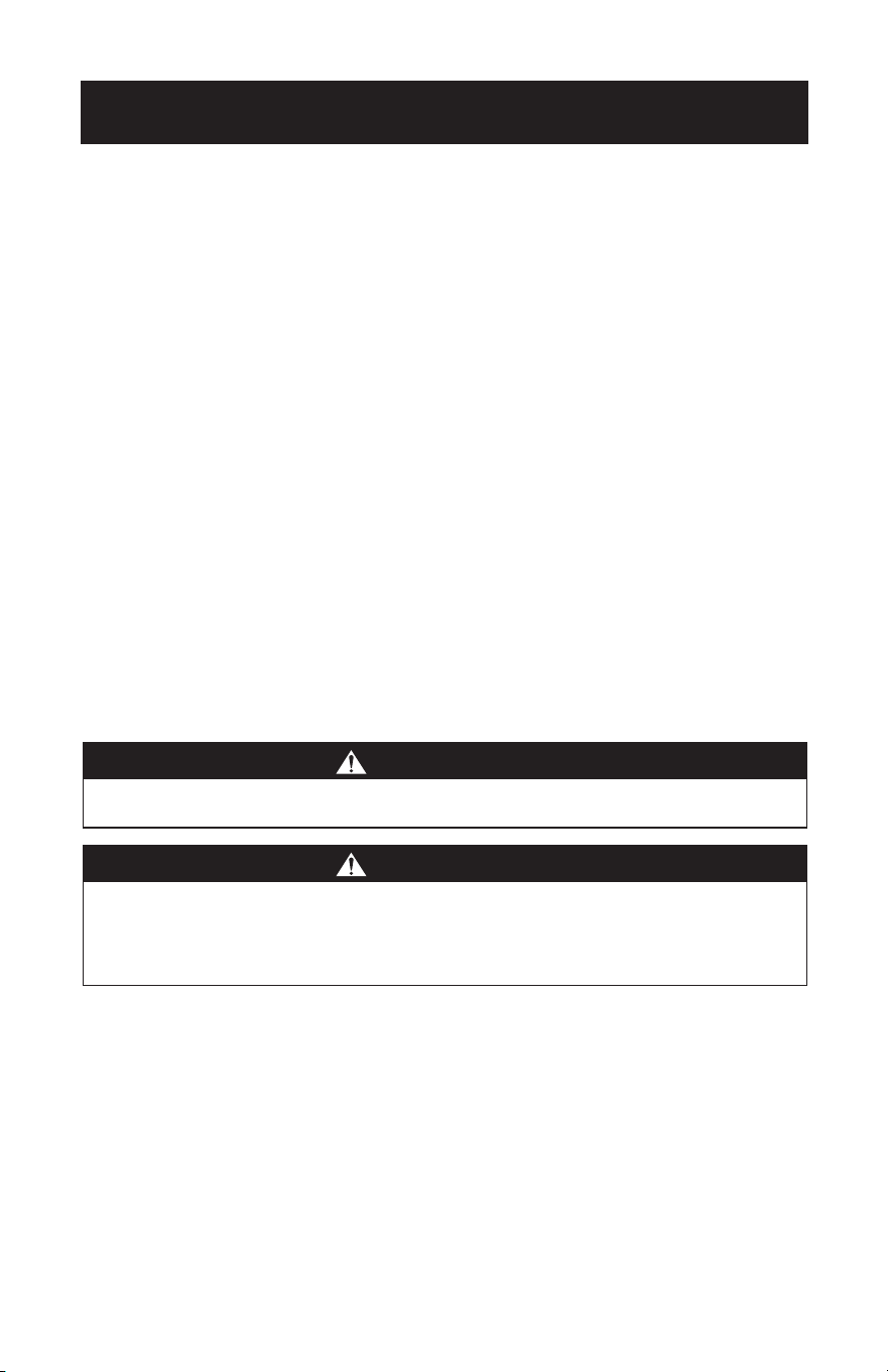
WARNING
To reduce the risk of fire or electric shock, do not use this fan with any solid-state
speed control device.
WARNING
To reduce the risk of personal injury, do not bend the blade brackets when installing
the brackets, balancing the blades, or cleaning the fan. Do not insert forgeign objects
in between rotating fan blades. Use only with light kits marked suitable for use in
damp locations.
Page 5
SAFETY INFORMATION
HANDLING ALKALINE BATTERIES
1. Should fluid from the battery accidentally get into your eyes, there is a threat
of loss of eyesight, do not rub them. Immediately rinse your eyes with clean tap
water and then consult a physician immediately.
2. Do not put the battery in a fire, expose it to heat, dismantle or modify it. If the
insulation or safety valve is damaged, the battery may leak fluid, overheat or
explode.
3. Do not insert the battery with the poles reversed. Doing so may cause some
abnormality or a short and the battery may leak fluid, overheat or explode.
4. Keep the battery out of the reach of children. If the battery is swallowed, contact a
physician immediately.
5. If the alkali fluid gets in your mouth, rinse your mouth with water and contact a
physician immediately.
6. If the alkali fluid gets on your skin or clothes, it may burn your skin, thoroughly
rinse the aected area with tap water.
7. Do not mix new and old batteries or other makes of batteries. The dierent
attributes may cause the battery to leak fluid, overheat or explode.
8. This battery was not made to be recharged. Recharging this battery may damage
the insulation or internal structure and may cause the battery to leak fluid,
overheat or explode.
9. Do not damage or remove the label on the exterior of the battery. Doing so may
cause the battery to short, leak fluid, overheat or explode.
10. Do not drop, throw or expose the battery to extreme impact. Doing so may cause
the battery to leak fluid, overheat or explode.
11. Do not alter the shape of the battery. If the insulation or safety valve is damaged,
the battery may leak fluid, overheat or explode.
12. Immediately remove batteries when they have lost all power. Leaving the batteries
in the unit for a long time may cause the batteries to leak fluid, overheat or
explode due to gas that is generated by the batteries.
Contact your local government for disposal practices in your area.
WARNING
When handling alkaline batteries, basic safety precautions
should be followed, including the following

Page 6
SET UP & USE
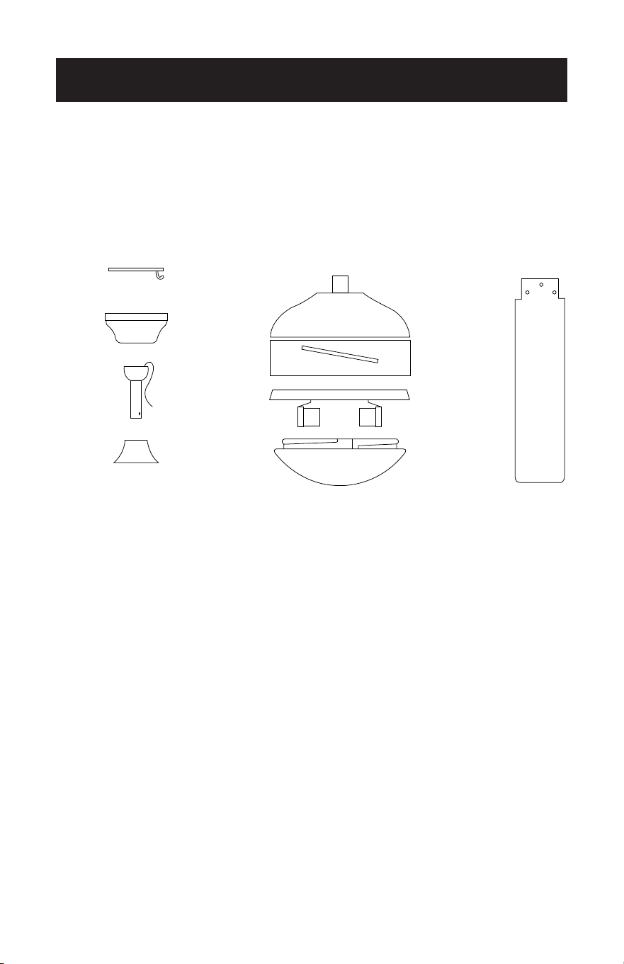
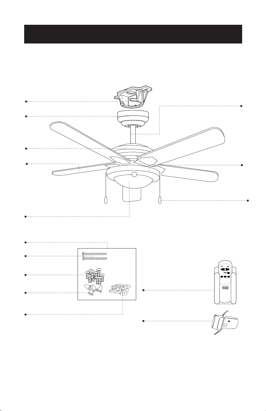
PARTS
Mounting Bracket
Blade (5)
*Light Fixture
*Remote Control
and holder
Hardware Pack
* Batteries not included with remote. Use (2) size “AA” alkaline batteries.
* Bulbs not included with light fixture (2) type A-19, 60W bulbs required.
* Not all models contain a remote control, remote receiver and remote control holder.
Only model BCF5211R.
* Not all models contain pull chains and extensions. Only model BCF5211
Canopy
Screws
Screws for fan blade
Wire Connectors
Washers for fan blade
0
1
2 3
Motor Housing
Slide Switch
6” Downrod
Pull Chains (2)
Pull Chain Extentions (2)
*Remote Receiver
Page 7
SET UP & USE
Ladder
Screwdrivers
Pliers
Wire Strippers
Electrical Tape
(optional) Power drill and drill bit
A. Mounting Bracket
B. Canopy
C. 6” Downrod assembly
D. Yoke Cover
E. Fan Motor Assembly
F. Motor Cover
G. Glass Cover (Light Fixture)
H. Fan Blades (5)
BCF5211R
Remote Control
Remote Receiver
Remote Control Holder
2 Screws for Remote Control Holder
BCF5211
Pull Chain (2)
Pull Chain Extensions (2)
A
B E
F
G
C
D
H
RECOMMENDED TOOLS
PARTS INCLUDED

Page 8
SET UP & USE
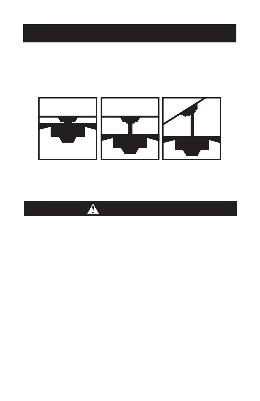
FEATURES
Downrod
Installation
For normal ceilings
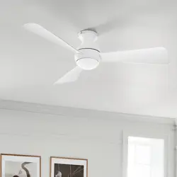
Vaulted Ceiling
Installation
May require a
longer downrod
(sold separately)
CAUTION
To reduce the risk of injury to persons, the fan must be installed so that the blades are
at a height greater than 7 feet (2.1 meters) above the floor.
This fan is designed for indoor use only.
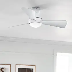
Flush
Installation
For normal ceilings
SET UP & USE
Page 9
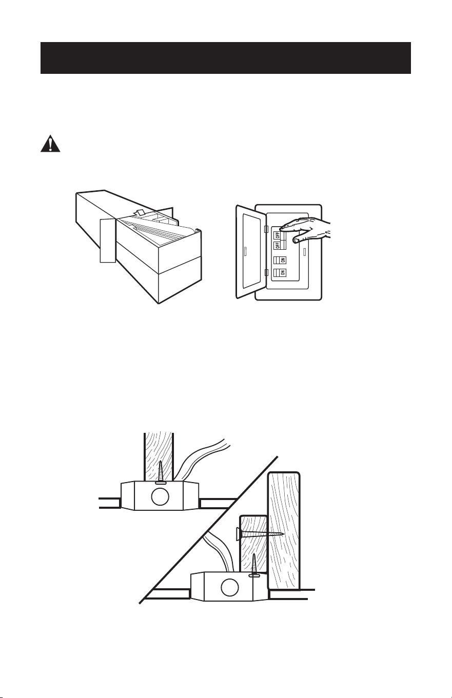
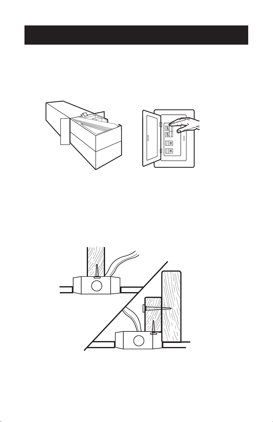
PREPARING FOR INSTALLATION
1. Unpack and inspect fan carefully to be certain all contents are included.
WARNING: Turn o power at the breaker box or fuse panel to avoid possible
electrical shock.
2. Use a listed metal outlet box suitable for fan support (rated for 35 lbs (15.9 kg)).
Before attaching fan to outlet box, ensure the outlet box is securely fastened by at
least two points to a structural ceiling member (a loose box will cause the fan to
wobble).

Page 10
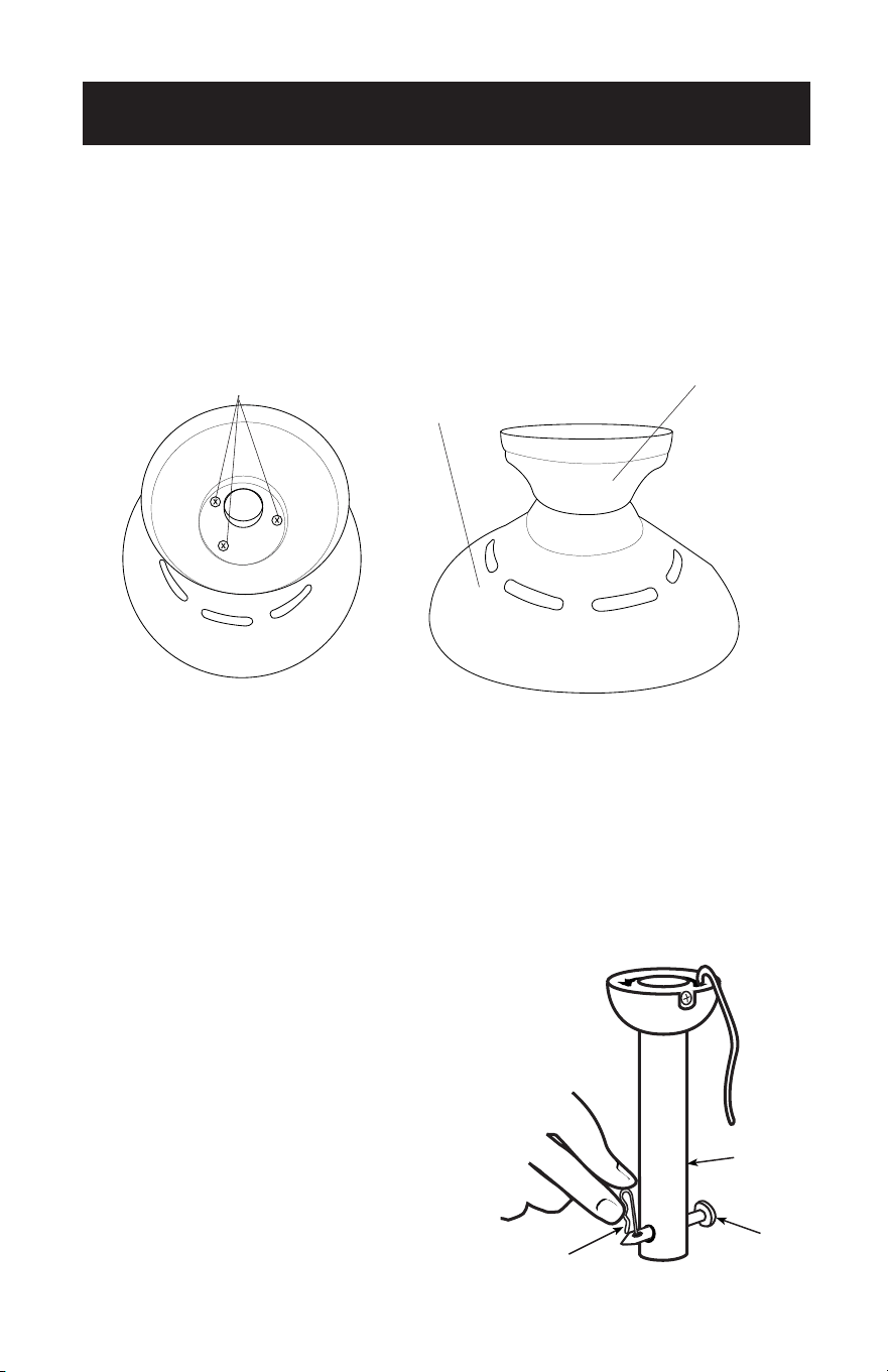
MOUNTING BRACKET INSTALLATION
3. Remove the screws from the two mating holes (2) on the canopy. Loosen (do not
remove) the screws in the mating slots (1) on the canopy. Rotate the mounting
bracket and remove from the canopy.
2
1
1
2
2
1
1
2
SET UP & USE

Page 11
SET UP & USE
4. Install mounting bracket to outlet box in ceiling using the screws and washers
provided with the outlet box.

Page 12
SET UP & USE
5. Choose a MOUNTING OPTION (Shown on page 8):
FLUSH INSTALLATION OPTION
If installing flush, remove the screws from the canopy and reinstall 3 screws to attach
the canopy to the motor housing as shown.
Complete the wiring options as shown on page 15. It will require two people to
complete this installation. Someone will need to hold the canopy and motor housing,
while the wires are being connected.
If you are installing a ceiling fan with a remote receiver, proceed to page 16, step 12. If
you do not need to include a remote receiver, proceed to secure the fan to the ceiling
as shown on page 17, step 13.
NORMAL DOWNROD OPTION
6. Remove clamp pin (1) and cross pin (2) from
downrod (3). Proceed to DOWNROD
INSTALLATION page 13, step 7.
1
2
3
Screws
Motor
Housing
Canopy
Page 13
SET UP & USE
DOWNROD INSTALLATION
7. Insert motor wires through the selected downrod and insert the downrod into
the downrod coupling. Make sure to align the hole in the downrod with the hole
in the downrod coupling. Install cross pin (1) removed in step 6 through coupling
and downrod. Insert clamp pin (2) into cross pin until it snaps into place. Tighten
set screws (3) in coupling. Slide coupling cover (4) and canopy onto the downrod
above the coupling cover. PROCEED TO PAGE 14, STEP 8.
1
4
3
2
Downrod Coupling
1
4
3
2
Downrod Coupling

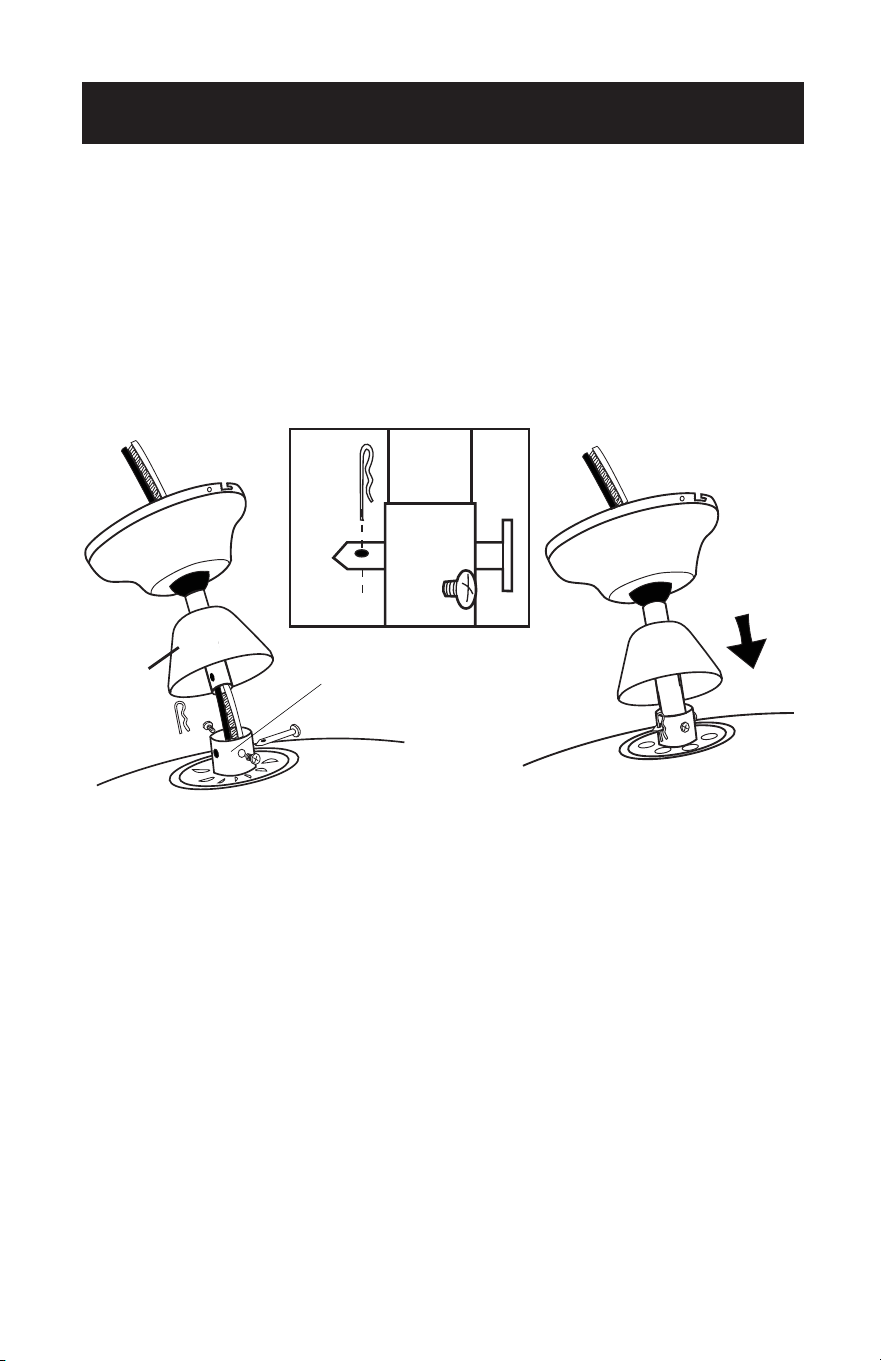
Page 14
MOUNTING
8. Carefully lift fan assembly onto mounting bracket. Rotate fan until notch on
downrod ball (1) engages the ridge on the mounting bracket (2). This will allow for
hands free wiring for downrod fan installation.
NOTE: If you are installing the fan flush, you will need assistance holding the fan while
doing the wiring.
SET UP & USE

Page 15
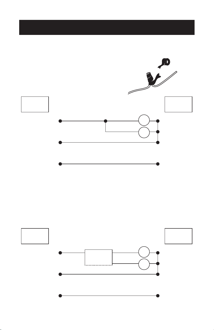
SET UP & USE
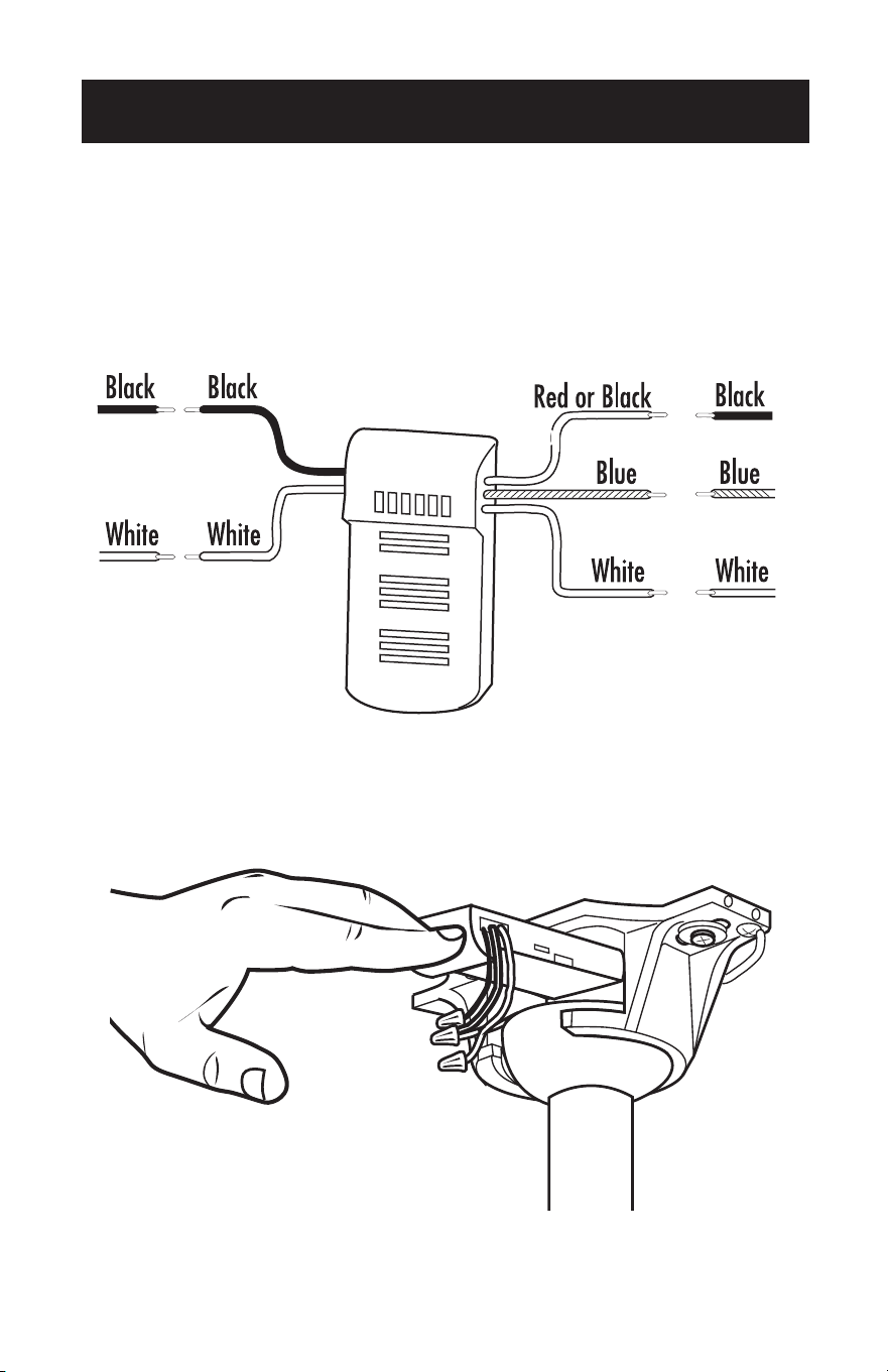
WIRING OPTIONS FOR BCF5211 WITH PULL
CHAIN
9. In order to make sure no bare wires are exposed
after making connections it is recommended to
wrap electrical tape around each wire connector
to secure wire from being disconnected.
Use supplied wire connectors to connect the wires.
WIRING OPTIONS FOR BCF5211R WITH
REMOTE
10. The frequency switches on your receiver and transmitter have been preset at the
factory. Please recheck to make sure the switches on transmitter and receiver are
set to the same position, any combination of settings will operate the fan as long
as the transmitter and receiver are set to the same position.
Use supplied wire connectors to connect the wires.
BLK BLK
BLUE
Fan
Light
GREEN
WHITE
REMOTE
RECEIVER
Live
Neutral
Ground
FANCEILING
Live
Neutral
Ground
BLK BLK
BLUE
Fan
Light
GREEN
WHITE
FANCEILING

Page 16
11. Make wiring connections from the ceiling and the fan motor to the remote receiver
as shown above. Connect using wire connectors (provided).
12. Once wiring has been completed insert the remote receiver at the top of the
mounting bracket as shown. For downrod fans this will be at the top of the
downrod ball.
Ceiling Fan
Ceiling Fan
SET UP & USE

Page 17
SET UP & USE
SECURE TO CEILING
13. The canopy has two mating slots (1) and two mating holes (2). Position both slots
on canopy directly under and in line with two screws in the mounting bracket (3).
Lift the canopy, allowing the two screws to slide into the mating slots. Rotate the
canopy until both screws from the mounting bracket drop into the slot recesses.
Tighten screws securely. Install two screws into the mating holes of the canopy and
tighten to secure the canopy to the mounting bracket.
NOTE: For downrod fans, slide the canopy up to the mounting bracket.
2
3
1
2
3
1
Page 18
SET UP & USE
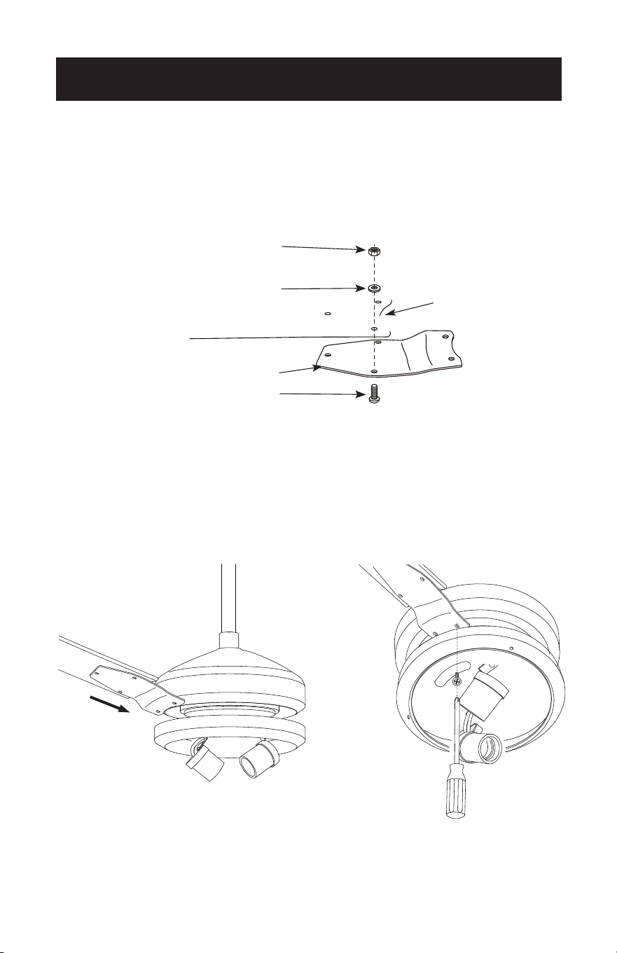
BLADE INSTALLATION
14. Attach the blade to the blade bracket as shown.
Insert the blade bracket to the fan motor housing. Secure each blade with the
provided screws and lock washers as shown. Slightly turn each blade after installation
and repeat the same step for each blade.
Hex Nut
Small Lock Washer
Washers
Blade Bracket
Blade Bracket Screws
Page 19
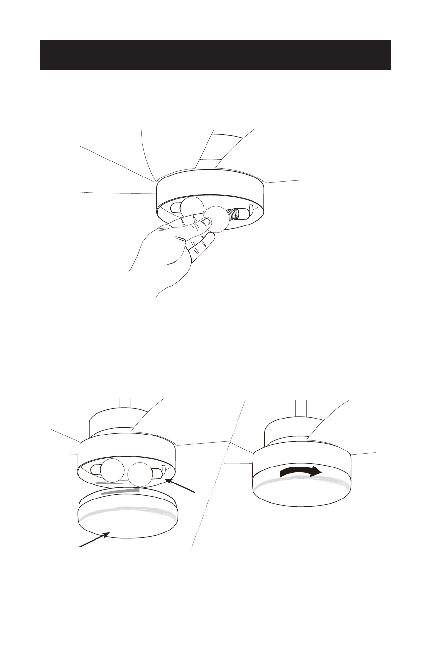
LIGHT FIXTURE INSTALLATION
15. Install 2 light bulbs Type A-19, 60W max (not included).
16. Locate the indentations on the neck of the glass (2) and align with the protrusions
from the light kit (1). Lift the glass up allowing the protrusions to engage the
indentations on the glass, and twist the glass clockwise to lock into place.
If your model has pull chains you can attach the pull chain extensions using the fobs.
SET UP & USE
1
2
1
2
Page 20
SET UP & USE
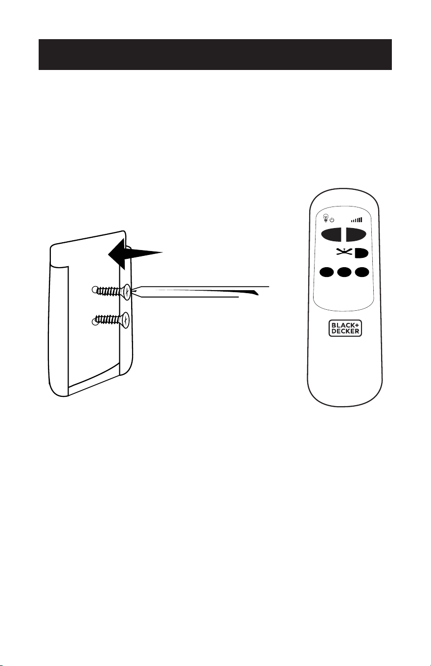
17. Model BCF5211R comes with a holder in order to store your remote.
Mount the remote control holder onto the wall using the screws provided. If you
do not wish to screw the remote holder into the wall, you may purchase some
adhesive at your local hardware store.
0
1
2 3

Page 21
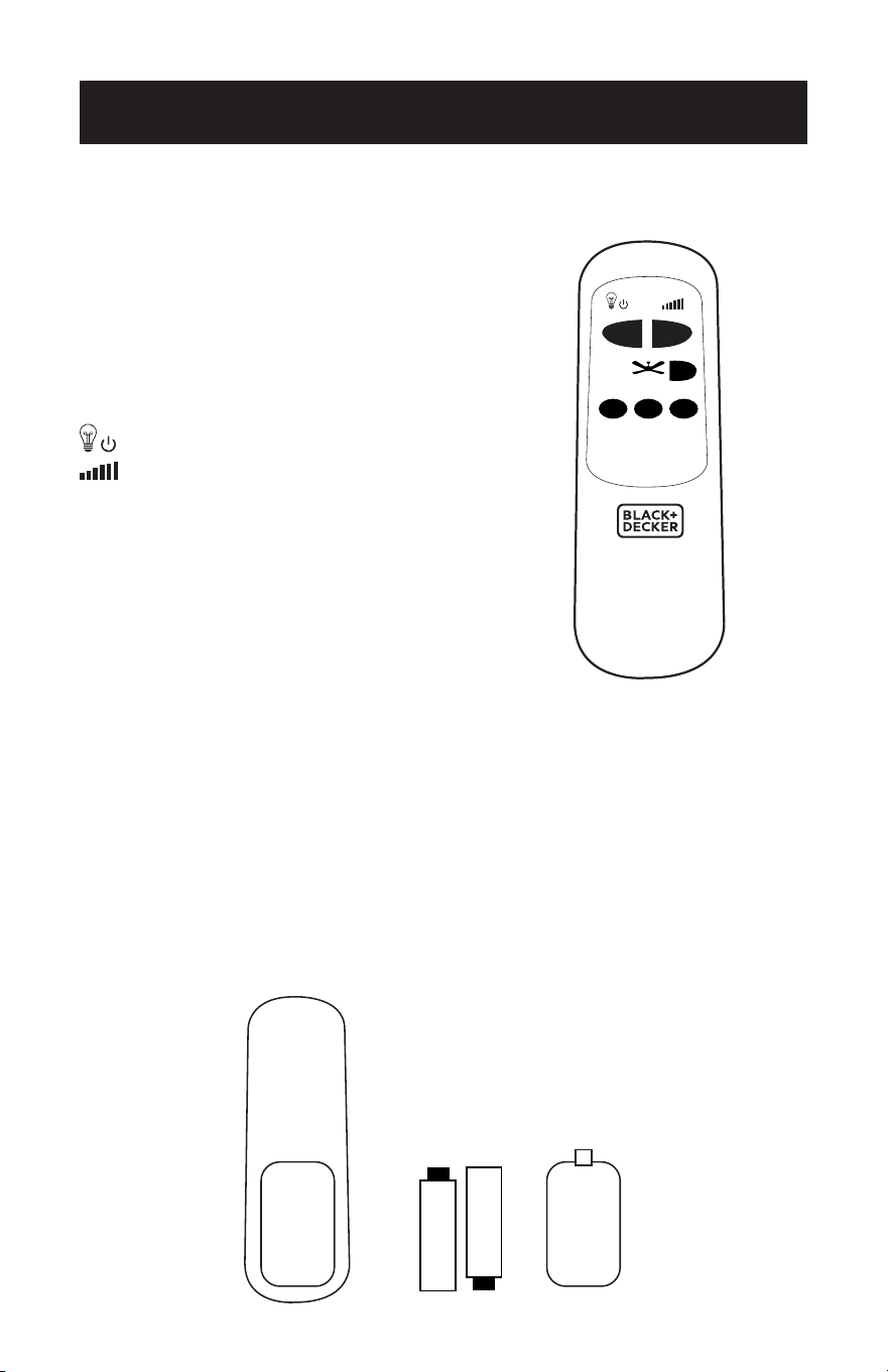
REMOTE CONTROL OPERATION
FOR MODEL BCF5211R
Operation button on the remote:
1 Fan high speed
2 Fan medium speed
3 Fan low speed
0 Fan off
Light on/off
Light dimmer
NOTE: Hold down to increase or decrease the light. The light has a memory function
so the light will stay at the same brightness as the last time it was turned off.
1. Battery Installation (batteries not included)
(1) Slide open the battery compartment cover.
(2) Insert 2 x “AA” batteries as shown below.
(3) Slide back on the battery cover.
NOTE: Use size “AA” alkaline batteries. Do not use rechargeable batteries.
SET UP & USE
0
1
2 3
–+
Remote Control
Battery Battery Cover
SET UP & USE
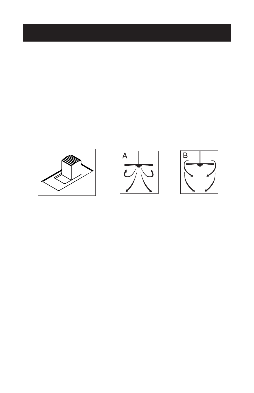
OPERATION
The slide switch controls direction, forward or reverse.
Warm weather - switch on left position.
Fan turns counterclockwise direction. A downward air flow creates a cooling eect as
shown in illustration A.
Cool weather - switch on right position (see image).
Fan turns clockwise direction. An upward airflow moves warm air o the ceiling area
as shown in illustration B (This function will usually be used in the winter).
NOTE: Turn o and wait for fan to stop before changing the setting
of the forward/reverse slide switch.
PULL CHAIN OPERATION
If your model comes equipped with pull chains one pull chain controls the light (on/
o). The other pull chain is for the fan speed.
1. The first pull will set the fan to high speed.
2. The second pull will set the fan to medium speed.
3. The third pull will set the fan to low speed.
4. The fourth pull will shut the fan o.
Page 22

Page 23
CLEANING + MAINTENANCE
1. Because of the fan’s natural movement, some connections may become loose.
Check the support connections, brackets, and blade attachments twice a year.
Make sure they are secure.
2. Clean your fan periodically to help maintain its new appearance over the years.
Do not use water when cleaning. This could damage the motor, or the wood, or
possibly cause electrical shock.
3. Use only a soft brush or lint-free cloth to avoid scratching the finish. The plating is
sealed with a lacquer coating to minimize discoloration or tarnishing.
4. There is no need to oil your fan. The motor has permanently lubricated bearings.
5. To change (2) size “AA” alkaline batteries, see page 21.
6. To change light bulbs, see page 19.
CLEANING + MAINTENANCE
Page 23

SET UP & USE
BEFORE YOU CALL FOR SERVICE
IF THE APPLIANCE FAILS TO OPERATE:
Check for a blown circuit fuse or a tripped main circuit breaker. If these seem to be
operating properly, test the outlet with another appliance.
IF NONE OF THE ABOVE SOLVES THE PROBLEM, CONTACT A QUALIFIED
TECHNICIAN. DO NOT TRY TO ADJUST OR REPAIR THE APPLIANCE YOURSELF.
IMPORTANT
DO NOT RETURN THIS PRODUCT TO THE STORE
If you have a problem with this product, please contact the
W Appliance Co. Customer Satisfaction Center at
844-299-0879 or service@appliance.com.
DATED PROOF OF PURCHASE, MODEL # AND SERIAL #
REQUIRED FOR WARRANTY SERVICE
Page 24
TROUBLESHOOTING & WARRANTY
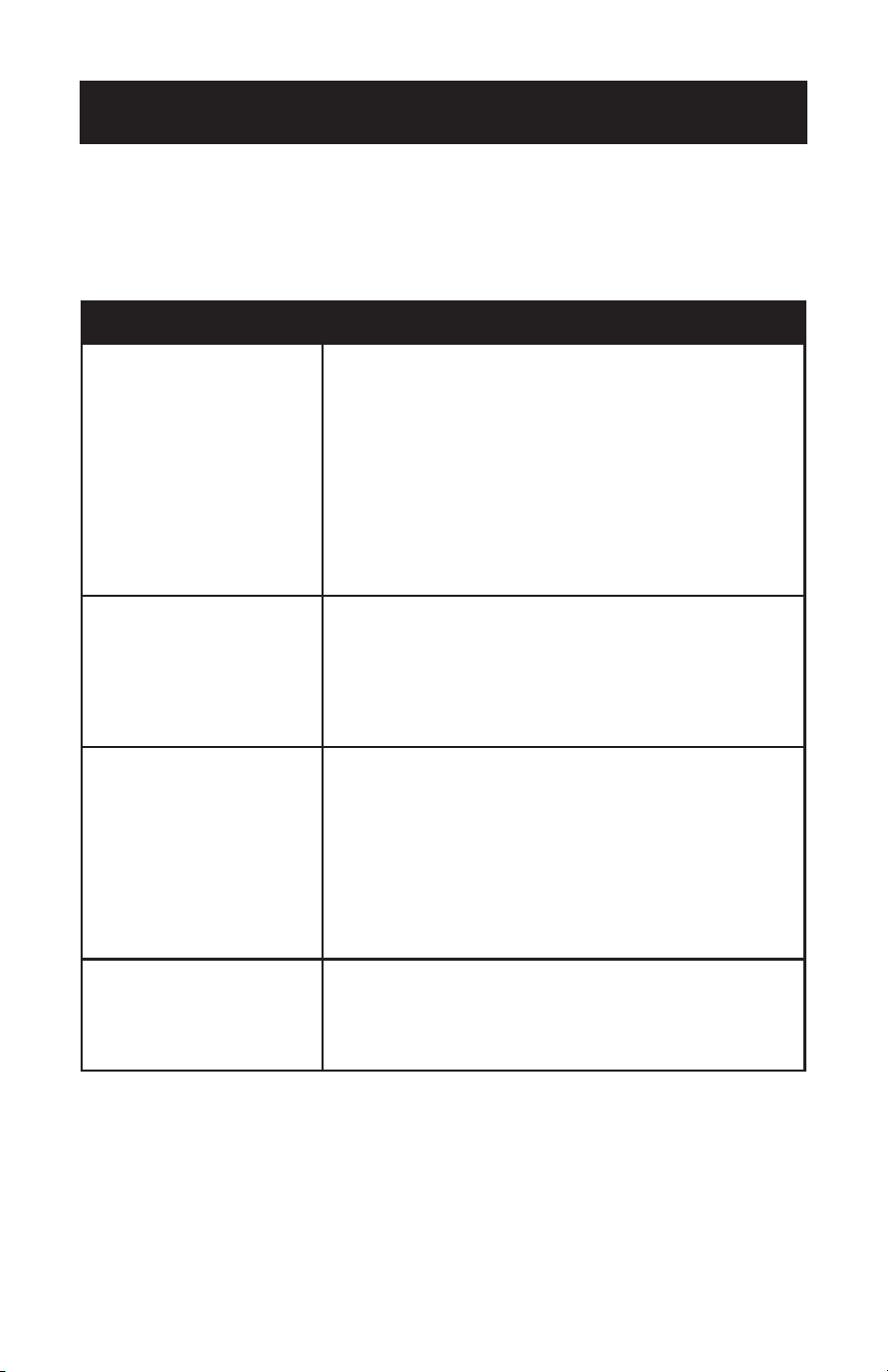
TROUBLE POSSIBLE REMEDY
If fan does not start
1. Check main and branch circuit fuses or circuit breakers.
2. Check wire connections as performed applicable installation
pages 11-16. CAUTION: Make sure main power is turned o.
3. Make sure forward/reverse switch is firmly in right or left
position. Fan will not operate when switch is in the middle.
4. If the fan still will not start, contact a qualified electrician. Do
not attempt to troubleshoot internal electrical connections
yourself.
5. If remote is being used, check batteries.
If fan sounds noisy
1. Check to make sure all screws in motor housing are snug
(not over tightened).
2. Check to make sure the screws which attach the fan blade
holder to the motor are tight.
3. Allow “break-in” period of 24 hours. Most noises associated
with a new fan will disappear after this period.
If fan wobbles
1. Check that all blades are screwed firmly into blade holders.
2. Check that all blade holders are tightened securely to motor.
3. Make sure that canopy and mounting bracket are tightened
securely to ceiling joist.
4. If blade wobble is still noticeable, interchanging two
adjacent (side by side) blades can redistribute the weight
and possibly result in smoother operation.
If light does not work
1. Check for faulty light bulbs.
2. Check to see that the wire connections in the switch
housing are connected.
3. If light kit will still not operate, contact a qualified electrician
for assistance.
Troubleshoot your problem by using the chart below. If the appliance still does not
work properly, contact W Appliance Co. customer service center. Customers must
never troubleshoot internal components.
Page 25

TROUBLESHOOTING & WARRANTY
LIMITED WARRANTY
Any repair, replacement, or warranty service,
and all questions about this product should be
directed to W Appliance Co. at 844-299-0879
from the USA or Puerto Rico.
W Appliance Co. warrants to the original purchaser
that the product will be free from defects in material,
parts and workmanship for the period designated for
this product. The warranty commences the day the
product is purchased and covers up to a period of 1
year (12 months) for labor/1 year (12 months) for parts
(manufacturing defects only).
W Appliance Co. agrees that it will, at its option,
replace the defective product with either a new
or remanufactured unit equivalent to your original
purchase during the warranty period.
Exclusions: This warranty does not apply to the
below:
1. If the appearance or exterior of
the product has been damaged or
defaced, altered or modified in design or
construction.
2. If the product original serial number
has been altered or removed or cannot
be readily determined.
3. If there is damaged due to power line
surge, user damage to the AC power
cord or connection to improper voltage
source.
4. If damage is due to general misuse,
accidents or acts of God.
5. If repair attempts are done by
unauthorized service agents, use of
parts other than genuine parts or parts
obtained from persons other than
authorized service companies.
6. On units that have been transferred
from the original owner.
7. On products that have been purchased
as refurbished, like new, second-hand, in
a “As-Is” or “Final Sale” terms.
8. To products used in a commercial or
rental setting.
9. To products used in settings other than
ordinary household use or used other
than in accordance with the provided
instructions.
10. To damages for service calls for
improper installations.
11. Transportation and shipping costs
associated with the replacement of the
unit.
12. Service calls to instruct you how to use
your product.
13. Service calls to repair or replace the
house fuse, reset the circuit breaker or
correct the wiring in the house.
REPAIR OR REPLACEMENT AS PROVIDED UNDER
THIS WARRANTY IS THE EXCLUSIVE REMEDY OF
THE CUSTOMER; W Appliance Co. SHALL NOT BE
LIABLE FOR ANY INCIDENTAL OR CONSEQUENTIAL
DAMAGES FOR BREACH OF ANY EXPRESS OR
IMPLIED WARRANTY ON THIS PRODUCT, EXCEPT
TO THE EXTENT PROHIBITED BY APPLICABLE LAW.
ANY IMPLIED WARRANTY OF MERCHANTABILITY
OF FITNESS FOR A PARTICULAR PURPOSE ON THIS
PRODUCT IS LIMITED TO THE DURATION OF THE
WARRANTY.
Some states do not allow the exclusion or limitations
of incidental or consequential damages, or limitations
on how long the warranty lasts. In these cases the
above exclusions or limitations may not apply to you.
This warranty gives you specific legal rights and you
may also have other rights which vary from state to
state.
Obtaining Service: To obtain service, product
literature, supplies or accessories please call
844-299-0879 to create a ticket for exchange/repair.
Please make sure to provide the date of purchase,
model number and a brief description of the problem.
Our customer service representative
will contact you or send detailed return instructions.
W Appliance Co. does not warrant that the appliance will work
properly in all environmental conditions, and makes no warranty
and representation, either implied or expressed, with respect
to the quality, performance, merchantability, or fitness for a
particular purpose other than the purpose identified within this
user’s manual. W Appliance Co. has made every eort to ensure
that this user’s manual is accurate and disclaims liability for any
inaccuracies or omissions that may have occurred. Information in
this user’s manual is subject to change without notice and does
not represent a commitment on the part of W Appliance Co.. W
Appliance Co. reserves the right to make improvements to this
user’s manual and/or to the products described in this user’s
manual at any time without notice. If you find information in this
manual that is incorrect, misleading, or incomplete, please contact
us at 844-299-0879.
W Appliance Co.
1356 Broadway
New York, NY 10018
Page 26

This device complies with part 15 of the FCC rules. Operation is subject to the
following two conditions: 1) This device may not cause harmful interference, and 2)
This device must accept any interference received, including interference that may
cause undesired operation. This equipment has been tested and found to comply
with the limits for a Class B digital device, pursuant to Part 15 of the FCC rules. These
limits are designed to provide reasonable protection against harmful interference
in a residential installation. This equipment generates, uses and can radiate radio
frequency energy and, if not installed and used in accordance with the instructions,
may cause harmful interference to radio communications. However, there is no
guarantee that the interference will not occur in a particular installation. If this
equipment does cause harmful interference to radio or television reception, which
can be determined by turning the equipment o and on, the user is encouraged to
try to correct the interference by one or more of the following measures: a) Reorient
or relocate the receiving antenna. b) Increase the separation between the equipment
and the receiver. c) Connect the equipment into an outlet dierent from that
which the receiver is connected. d) Consult the dealer or an experienced radio/TV
technician for help.

Page 28
MANUEL D’UTILISATION
VENTILADOR DE TECHO DE 52”
Merci d’avoir choisi BLACK+DECKER!
VEUILLEZ LIRE AVANT DE RETOURNER CE PRODUIT POUR
QUELQUE RAISON.
Si vous avez une question ou rencontrez un problème avec votre achat
BLACK+DECKER, allez à www.blackanddecker.com/instantanswers
Si vous ne trouvez pas la réponse ou n’avez pas accès à Internet, appelez
844-299-0879 de 10h30 à 18h30 HNE du lun. au ven. pour parler avec un
agent. Veuillez avoir le numéro de catalogue disponible lorsque vous appelez.
CONSERVEZ CE MANUEL POUR TOUTE CONSULTATION
ULTÉRIEURE.
NUMÉRO DE CATALOGUE
BCF5211
BCF5211R

Page 30
Merci d’avoir acheté notre produit
BLACK+DECKER. Ce manuel facile
à utiliser vous aidera à tirer le
meilleur parti de ventilateur.
N’oubliez pas d’enregistrer le
modèle et numéros de série. Ils sont
sur une étiquette à l’arrière.
Agrafez votre reçu à votre manuel.
Vous en aurez besoin pour obtenir un service de garantie.
Numéro de modèle
Numéro de série
Date d’achat
ENREGISTREMENT DU PRODUIT
TABLE DES MATIÈRES
INFORMATIONS DE SÉCURITÉ
Information sur la sécurité .............................................................................................................................................31-32
Manipulation des Piles Alcalines .....................................................................................................................................33
CONFIGURATION ET UTILISATION
Pièces ..................................................................................................................................................................................... 34-35
Caractéristiques ....................................................................................................................................................................... 36
Préparation à l’Installation .................................................................................................................................... 37
Installation du Support de Montage ..........................................................................................................38-39
Montage du Ventilateur au Plafond ........................................................................................................... 40-42
Options de Câblage ....................................................................................................................................... 43-44
Fixation du Ventilateur au Plafond ................................................................................................................... 45
Installation de Pale ................................................................................................................................................ 46
Installation du Luminaire ......................................................................................................................................47
Fonctionnement de la Télécommande ..................................................................................................... 48-49
Opération ................................................................................................................................................................. 50
Nettoyage + Maintenance ....................................................................................................................................51
DÉPANNAGE ET GARANTIE
Avant d’Appeler Pour Le Service .......................................................................................................................52
Service Client .......................................................................................................................................................... 52
Dépannage ..............................................................................................................................................................53
Garantie Limitée ....................................................................................................................................................................54
Page 31
INFORMATIONS DE SÉCURITÉ
CONSIGNES DE SÉCURITÉ
IMPORTANTES
1. LIRE TOUTES LES INSTRUCTIONS AVANT UTILISATION
2. Les travaux d’installation et le câblage électrique doivent être
eectués par une ou des personnes qualifiées conformément à tous
les codes et normes applicables, y compris la construction résistante
au feu.
3. Utilisez cet appareil uniquement de la manière prévue par le
fabricant. Si vous avez des questions, contactez le fabricant.
4. Après avoir eectué les connexions des fils, poussez les connexions
doucement dans la boîte de sortie avec les écrous de fil vers le haut.
Les fils doivent être écartés avec le conducteur mis à la terre et le
conducteur de mise à la terre de l’équipement d’un côté de la boîte
de sortie et le conducteur non mis à la terre de l’autre côté de la
boîte de sortie.
5. Avant de commencer l’installation du ventilateur, mettez le panneau
de service hors tension et verrouillez les moyens de déconnexion du
service afin d’éviter toute mise sous tension accidentelle. Lorsque les
moyens de déconnexion du service ne peuvent pas être verrouillés,
fixez fermement un dispositif d’avertissement proéminent, tel qu’une
étiquette, sur le panneau de service.
6. Soyez prudent! Lisez toutes les instructions et les informations de
sécurité avant d’installer votre nouveau ventilateur. Consultez les
schémas d’assemblage qui l’accompagnent.
WARNING
POUR RÉDUIRE LE RISQUE D’INCENDIE, DE CHOC ÉLECTRIQUE OU DE BLESSURE
PERSONNELLE, INSTALLER SUR UNE BOÎTE DE SORTIE MARQUÉE “ACCEPTABLE
POUR UN SUPPORT DE VENTILATEUR DE 35 LIVRES (15.9 KG) OU MOINS” ET
UTILISER LES VIS DE MONTAGE FOURNIES AVEC LA BOÎTE DE SORTIE ET/OU LE
SUPPORTER DIRECTEMENT DE LA STRUCTURE DU BÂTIMENT. LA PLUPART DES
BOÎTES DE SORTIE COURAMMENT UTILISÉES POUR LE SOUTIEN DES LUMINAIRES
NE SONT PAS ACCEPTABLES POUR LE SOUTIEN DU VENTILATEUR ET PEUVENT
AVOIR BESOIN D’ÊTRE REMPLACÉES. CONSULTER UN ÉLECTRICIEN QUALIFIÉ EN
CAS DE DOUTE.
ATTENTION
ATTENTION - Dangers ou pratiques
dangereuses qui POURRAIENT
entraîner des blessures graves ou
la mort
DANGER
DANGER - Dangers immédiats qui
entraîneront des blessures graves
ou la mort
MISE EN GARDE
MISE EN GARDE - Dangers ou
pratiques dangereuses pouvant
entraîner des blessures corporelles
mineures

Page 32
INFORMATIONS DE SÉCURITÉ
7. Lors de la coupe ou du perçage dans le mur ou le plafond, ne pas
endommager le câblage électrique et les autres accessoires cachés.
8. Assurez-vous que le site d’installation choisi permet aux pales du
ventilateur de tourner sans aucune obstruction. Laissez un espace
minimum de 7 pieds (2.1 mètres) du sol jusqu’au bord traînant de la
pale.
9. Pour réduire les risques d’incendie, d’électrocution ou de blessure
personnelle, ce ventilateur doit être installé sur une boîte de sortie
indiquée pour le support du ventilateur. Et utilisez les vis de montage
fournies avec la boîte de sortie. (Le support doit supporter au moins
35 livres. (15.9 kg)
10. AVERTISSEMENT: POUR RÉDUIRE LE RISQUE DE BLESSURE
PERSONNELLE Ne pliez pas les porte-pales pendant l’installation
sur le moteur, l’équilibrage ou le nettoyage. N’insérez pas d’objet
étranger entre les pales rotatives.
11. Fixez le support de montage en utilisant uniquement le matériel
fourni avec le boîtier de sortie. Le ventilateur ne doit être installé
que sur une boîte de sortie portant la mention “Acceptable pour le
Support de Ventilateur”.
12. Ne pas installer dans une zone de 3 pieds horizontalement et de 8
pieds verticalement à partir du haut du seuil de la baignoire ou de la
cabine de douche.
13. Avant l’entretien ou le nettoyage de l’unité, mettez le panneau de
service hors tension et verrouillez les moyens de déconnexion du
service afin d’éviter toute mise sous tension accidentelle. Lorsque les
moyens de déconnexion du service ne peuvent pas être verrouillés,
fixez fermement un dispositif d’avertissement proéminent, tel qu’une
étiquette, sur le panneau de service.
14. Toutes les vis de blocage doivent être vérifiées et resserrées si
nécessaire avant l’installation.
15. Les travaux d’installation et le câblage électrique doivent être
eectués par des personnes qualifiées conformément aux codes et
aux normes applicables, y compris la construction résistante au feu.
SAUVEGARDER CES INSTRUCTIONS
USAGE DOMESTIQUE SEULEMENT
Page 33
INFORMATIONS DE SÉCURITÉ
MANIPULATION DES PILES ALCALINES
1. Si le liquide de la pile entre accidentellement dans vos yeux, il y a une menace de
perte de la vue, ne pas les frotter. Rincez immédiatement les yeux avec de l’eau
propre du robinet et consultez immédiatement un médecin.
2. Ne mettez pas la pile au feu, ne l’exposez pas à la chaleur, ne la démontez pas et ne
la modifiez pas. Si l’isolation ou la soupape de sécurité est endommagée, la pile
peut fuir, surchauer ou exploser.
3. N’insérez pas la pile avec les pôles inversés. Cela pourrait provoquer une anomalie
ou un court-circuit et la pile pourrait fuir, surchauer ou exploser.
4. Gardez la pile hors de portée des enfants. Si la pile est avalée, contactez
immédiatement un médecin.
5. Si le liquide alcalin pénètre dans votre bouche, rincez-vous la bouche avec de l’eau
et contactez immédiatement un médecin.
6. Si le liquide alcalin s’infiltre sur la peau ou les vêtements, cela peut brûler votre
peau, rincer abondamment la zone aectée avec de l’eau du robinet.
7. Ne mélangez pas des piles neuves et usagées ou d’autres marques de piles. Les
diérents attributs peuvent entraîner une fuite de la pile, une surchaue ou une
explosion.
8. Cette pile n’a pas été faite pour être rechargée. Recharger cette pile peut
endommager l’isolation ou la structure interne et provoquer une fuite de liquide,
une surchaue ou une explosion de la pile.
9. Ne pas endommager ou enlever l’étiquette sur l’extérieur de la pile. Cela peut
provoquer un court-circuit de la pile, une fuite de liquide, une surchaue ou une
explosion.
10. Ne pas laisser tomber, jeter ou exposer la pile à un impact extrême. Cela pourrait
entraîner une fuite de la pile, une surchaue ou une explosion.
11. Ne modifiez pas la forme de la pile. Si l’isolation ou la soupape de sécurité est
endommagée, la pile peut fuir, surchauer ou exploser.
12. Retirez immédiatement les piles quand elles ont perdu toute leur puissance. Si
vous laissez les piles dans l’appareil pendant une longue période, les piles risquent
de fuir, de surchauer ou d’exploser à cause du gaz produit par les piles.
Contactez votre gouvernement local pour les pratiques d’élimination dans votre
région.
ATTENTION
Lors de la manipulation des piles alcalines, des précautions de sécurité
de base doivent être suivies, y compris les suivantes

Page 34
CONFIGURATION ET UTILISATION
PIÈCES
Support de Montage
Pale (5)
*Luminaire
*Télécommande et support
Paquet Quincaillerie
* Piles non fournies avec la télécommande. Utilisez (2) piles alcalines “AA”.
* Ampoules non incluses avec le luminaire (2) ampoules type A-19, de 60W requises.
* Tous les modèles ne contiennent pas de télécommande, de récepteur à distance et
de support de télécommande. Seulement le modèle BCF5211R.
* Tous les modèles ne contiennent pas de chaînes à tirer et d’extensions. Seulement le
modèle BCF5211
Canopée
Vis
Vis pour pale de
ventilateur
Serre-fils
Rondelles pour pale de ventilateur
0
1
2 3
Boîtier du Moteur
Interrupteur à Glissière
Tige de 6”
Chaînes À Tirer (2)
Extensions de Chaîne À Tirer (2)
*Récepteur à Distance

Page 35
CONFIGURATION ET UTILISATION
Échelle
Tournevis
Pince
Pince à Dénuder
Ruban Électrique (en option)
Perceuse et forêt
A. Support de Montage
B. Canopée
C. Ensemble de tige de 6po
D. Couvercle de Culasse
E. Assemblée du Moteur du Ventilateur
F. Couvercle de Moteur
G. Couvercle de Verre (Luminaire)
H. Pales de Ventilateur (5)
BCF5211R
Télécommande
Récepteur à Distance
Support de Télécommande
2 Vis pour Support de Télécommande
BCF5211
Chaîne à Tirer (2)
Extensions de Chaîne à Tirer (2)
A
B E
F
G
C
D
H
OUTILS RECOMMANDÉS
PIÈCES INCLUSES
Page 36
CONFIGURATION ET UTILISATION
CARACTÉRISTIQUES
Installation
sur Tige
Pour les plafonds
normaux
Installation au
Plafond Voûté
Peut nécessiter une
tige de suspension
plus longue (vendue
séparément)
Pour réduire le risque de blessure aux personnes, le ventilateur doit être installé de
sorte que les pales soient à une hauteur supérieure
à 2.1 mètres (7 pieds) au-dessus du sol.
Ce ventilateur est conçu pour une utilisation intérieur.
ATTENTION
Installation
Encastrée
Pour les plafonds
normaux
CONFIGURATION ET UTILISATION
Page 37
PRÉPARER POUR L’INSTALLATION
1. Déballez et inspectez soigneusement le ventilateur pour vous assurer que tout le
contenu est inclus. Coupez l’alimentation à la boîte à fusibles pour éviter tout risque
d’électrocution.
2. Utilisez une boîte de sortie en métal homologuée convenant au support du
ventilateur (capacité nominale de 35 livres (15,9 kg)). Avant d’attacher le ventilateur
à la boîte de sortie, assurez-vous que la boîte de sortie est solidement fixée par au
moins deux points à un membre de plafond structurel (une boîte lousse fera branler
le ventilateur).

Page 38
INSTALLATION DU SUPPORT DE MONTAGE
3. Retirez les vis des deux trous correspondants (2) sur la canopée. Desserrez (ne
retirez pas) les vis dans les fentes d’accouplement (1) sur la canopée. Tournez le
support de montage et retirez-le de la canopée.
2
1
1
2
2
1
1
2
CONFIGURATION ET UTILISATION

Page 39
CONFIGURATION ET UTILISATION
4. Installez le support de montage sur la boîte de sortie du plafond à l’aide des vis et
des rondelles fournies avec la boîte de sortie.
Page 40
CONFIGURATION ET UTILISATION
5. Choisissez une OPTION DE MONTAGE (illustrée à la page 8):
OPTION D’INSTALLATION ENCASTRÉE
Si vous l’installez encastré, retirez les vis de la canopée et réinstallez 3 vis pour fixer la
canopée au boîtier du moteur comme indiqué.
Complétez les options de câblage comme indiqué à la page 15. Il faudra deux
personnes pour terminer cette installation. Quelqu’un devra tenir la canopée et le
boîtier du moteur, pendant que les fils sont connectés.
Si vous installez un ventilateur de plafond avec un récepteur à distance, passez à la
page 16, étape 12. Si vous n’avez pas besoin d’inclure un récepteur à distance, fixez le
ventilateur au plafond comme indiqué à la page 17, étape 13.
OPTION DE TIGE DE
SUSPENSION NORMALE
6. Retirez la goupille de serrage (1) et la
goupille transversale (2) de la tige de
suspension (3). Passez à l’INSTALLATION
DE LA TIGE DE SUSPENSION page 13, étape 7.
1
2
3
Des vis Logement
du moteur
Canopée

Page 41
CONFIGURATION ET UTILISATION
INSTALLATION DE LA TIGE DE SUSPENSION
7. Insérez les fils du moteur dans la tige de suspension sélectionnée et insérez la
tige dans le couplage de la tige. Assurez-vous d’aligner le trou de la tige avec le
trou dans le couplage de la tige. Installez la goupille (1) retirée à l’étape 6 à travers
le couplage et la tige. Insérez la goupille de serrage (2) dans la goupille jusqu’à
ce qu’elle s’enclenche. Serrer les vis de pression (3) dans le couplage. Glisser le
couvercle de couplage (4) et la canopée sur la tige au-dessus du couvercle de
couplage. PASSEZ À LA PAGE 14, ÉTAPE 8.
1
4
3
2
Downrod Coupling
1
4
3
2
Downrod Coupling

Page 42
MONTAGE
8. Soulevez soigneusement l’assemblage du ventilateur sur le support de montage.
Tournez le ventilateur jusqu’à ce que l’encoche de la bille de guidage (1) s’engage
dans l’arête du support de montage (2). Cela permettra un câblage à mains libres
pour l’installation à tige du ventilateur.
REMARQUE: Si vous installez le ventilateur encastré, vous aurez besoin d’aide pour
tenir le ventilateur pendant le câblage.
CONFIGURATION ET UTILISATION
Page 43
CONFIGURATION ET UTILISATION
OPTIONS DE CÂBLAGE POUR BCF5211 AVEC
CHAÎNE À TIRER
9. Afin de s’assurer qu’aucun fil dénudé n’est exposé
après avoir eectué les connexions, il est recommandé
d’enrouler du ruban électrique autour de chaque
connecteur de fil pour empêcher le fil de se déconnecter.
Utilisez les connecteurs de fils fournis pour connecter les fils.
OPTIONS DE CÂBLAGE POUR BCF5211R AVEC
TÉLÉCOMMANDE
10. Les commutateurs de fréquence de votre récepteur et émetteur ont été préréglés
en usine. Veuillez revérifier que les commutateurs de l’émetteur et du récepteur
sont réglés sur la même position, toute combinaison de réglages fera fonctionner
le ventilateur tant que l’émetteur et le récepteur sont réglés sur la même position.
Utilisez les connecteurs de fils fournis pour connecter les fils.
BLK BLK
BLUE
Fan
Light
GREEN
WHITE
REMOTE
RECEIVER
Live
Neutral
Ground
FANCEILING
Live
Neutral
Ground
BLK BLK
BLUE
Fan
Light
GREEN
WHITE
FANCEILING
Page 44
11. Eectuez les connexions de câblage du plafond et du moteur du ventilateur
au récepteur à distance comme indiqué ci-dessus. Connectez en utilisant des
connecteurs de fils (fournis).
12. Une fois le câblage terminé, insérez le récepteur à distance en haut du support
de montage comme indiqué. Pour les ventilateurs à tige, ce sera au sommet de la
balle.
Ceiling Fan
Ceiling Fan
CONFIGURATION ET UTILISATION

Page 45
CONFIGURATION ET UTILISATION
SÉCURISER AU PLAFOND
13. La canopée comporte deux fentes de couplage (1) et deux trous de couplage (2).
Positionnez les deux fentes de la canopée directement sous et alignées avec les
deux vis du support de montage (3). Soulevez la canopée en laissant les deux vis
glisser dans les fentes de couplage. Tournez la canopée jusqu’à ce que les deux vis
du support de montage tombent dans les encoches de la fente. Serrez fermement
les vis. Installez deux vis dans les trous de couplage de la canopée et serrez pour
fixer la canopée au support de montage.
REMARQUE: Pour les ventilateurs à tige, faites glisser la canopée jusqu’au support
de montage.
2
3
1
2
3
1

CONFIGURATION ET UTILISATION
INSTALLATION DE LA PALE
14. Fixez la lame au support de lame comme indiqué.
Insérez le support de lame dans le boîtier du moteur du ventilateur. Fixez chaque
lame avec les vis et les rondelles de blocage fournies, comme indiqué. Tournez
légèrement chaque lame après l’installation et répétez le même pas pour chaque
lame.
Hex Nut
Small Lock Washer
Washers
Blade Bracket
Blade Bracket Screws
Page 46

Page 47
INSTALLATION DE LUMINAIRE
15. Installez 2 ampoules de type A-19, 60W max (non incluses).
16. Localisez les indentations sur le col du verre (2) et alignez-les avec les saillies
du kit d’éclairage (1). Soulevez le verre en laissant les saillies s’engager dans les
indentations sur le verre et tournez le verre dans le sens horaire pour le verrouiller
en place.
Si votre modèle a des chaînes à tirer, vous pouvez attacher les extensions de chaîne à
tirer en utilisant les breloques.
CONFIGURATION ET UTILISATION
1
2
1
2

Page 48
CONFIGURATION ET UTILISATION
17. Le modèle BCF5211R est livré avec un support pour remiser votre télécommande.
Montez le support de télécommande sur le mur à l’aide des vis fournies. Si vous ne
souhaitez pas visser le support de télécommande dans le mur, vous pouvez acheter
de l’adhésif dans votre quincaillerie locale.
0
1
2 3
Page 49
FONCTIONNEMENT DE LA TÉLÉCOMMANDE
POUR LE MODÈLE BCF5211R
Bouton d’opération sur la télécommande:
1 Ventilateur haute vitesse
2 Ventilateur moyenne vitesse
3 Ventilateur basse vitesse
0 Ventilateur arrêt
Lumière marche/arrêt
Gradateur
REMARQUE: Maintenez enfoncé pour augmenter ou
diminuer la lumière. La lumière a une
fonction de mémoire an que la lumière
reste à la même luminosité que la dernière
fois qu’elle a été éteinte.
1. 1. Installation des Piles (piles non incluses)
(1) Faites glisser le couvercle du compartiment des piles pour l’ouvrir.
(2) Insérez 2 piles “AA” comme indiqué ci-dessous.
(3) Replacez le couvercle de la pile.
REMARQUE: Utilisez des piles alcalines de type “AA”. Ne pas utiliser de piles
rechargeables.
CONFIGURATION ET UTILISATION
0
1
2 3
–+
Télécommande
Batterie
Couvercle de
la batterie

CONFIGURATION ET UTILISATION
OPÉRATION
Le commutateur à glissière commande la direction, vers l’avant ou vers l’arrière.
Temps chaud - l’interrupteur est en position de gauche.
Le ventilateur tourne dans le sens antihoraire. Un flux d’air vers le bas crée un eet de
refroidissement comme indiqué sur l’illustration A.
Temps frais - l’interrupteur est en position de droite (voir image).
Le ventilateur tourne dans le sens horaire. Un flux d’air vers le haut déplace l’air
chaud de la zone du plafond, comme indiqué sur l’illustration B (Cette fonction est
généralement utilisée en hiver).
REMARQUE: Éteignez et attendez que le ventilateur s’arrête avant de changer le
réglage de l’interrupteur coulissant avant/arrière.
OPÉRATION DE LA CHAÎNE À TIRER
Si votre modèle est équipé de chaînes à tirer, une chaîne à tirer commande la lumière
(marche/arrêt). L’autre chaîne à tirer est pour la vitesse du ventilateur.
1. Le premier tir mettra le ventilateur à haute vitesse.
2. Le deuxième tir mettra le ventilateur à vitesse moyenne.
3. Le troisième tir mettra le ventilateur à basse vitesse.
4. Le quatrième tir arrêtera le ventilateur.
Page 50

Page 51
NETTOYAGE + ENTRETIEN
1. À cause du mouvement naturel du ventilateur, certaines connexions peuvent se
desserrer. Vérifiez les connexions de support, les supports et les attaches de pale
deux fois par an. Assurez-vous qu’ils sont sécurisés.
2. Nettoyez votre ventilateur périodiquement pour aider à conserver son aspect neuf
au fil des ans. N’utilisez pas d’eau pour nettoyer. Cela pourrait endommager le
moteur ou le bois ou provoquer un choc électrique.
3. Utilisez uniquement une brosse douce ou un chion non pelucheux pour éviter de
rayer la finition. Le placage est scellé avec un revêtement de laque pour minimiser
la décoloration ou le ternissement.
4. Il n’y a pas besoin d’huiler votre ventilateur. Le moteur a des roulements lubrifiés à
vie.
5. Pour changer (2) piles alcalines “AA”, voir page 21.
6. Pour changer les ampoules, voir page 19.
NETTOYAGE + ENTRETIEN
Page 51

DÉPANNAGE ET GARANTIE
AVANT D’APPELER POUR LE SERVICE
SI L’APPAREIL NE FONCTIONNE PAS:
Assurez-vous que l’appareil est branché solidement. Si ce n’est pas le cas, retirez la
fiche de la prise, attendez 10 secondes et branchez-le à nouveau sécuritairement.
SI AUCUNE DE CES RÉPONSES RÉSOUT LE PROBLÈME, CONTACTEZ UN
TECHNICIEN QUALIFIÉ. N’ESSAYEZ PAS D’AJUSTER OU DE RÉPARER LE
CLIMATISEUR VOUS-MÊME.
IMPORTANT
NE PAS RETOURNER CE PRODUIT AU MAGASIN
Si vous avez un problème avec ce produit, veuillez
communiquer avec le W Appliance Co. Centre de Satisfaction
Client à 844-299-0879.
PREUVE D’ACHAT DATÉE, # DE MODÈLE ET # DE SÉRIE
REQUIS POUR LE SERVICE SOUS GARANTIE
Page 52
DÉPANNAGE ET GARANTIE
PROBLÈME SOLUTION POSSIBLE
Si le ventilateur ne démarre
pas
1. Vérifier les fusibles du circuit principal et de dérivation ou les
disjoncteurs.
2. Vérifiez les connexions des câbles comme indiqué dans les
pages d’installation applicables 11-16. ATTENTION: Assurez-
vous que l’alimentation principale est coupée.
3. Assurez-vous que l’interrupteur avant/arrière est fermement
dans la position de droite ou de gauche. Le ventilateur ne
fonctionne pas lorsque le’interrupteur est au milieu.
4. Si le ventilateur ne démarre toujours pas, contactez un
électricien qualifié. N’essayez pas de dépanner vous-même
les connexions électriques internes.
5. Si la télécommande est utilisée, vérifiez les piles.
Si le ventilateur semble
bruyant
1. Assurez-vous que toutes les vis du boîtier du moteur sont
bien serrées (pas trop serrées).
2. Assurez-vous que les vis qui fixent le support de la pale du
ventilateur au moteur sont bien serrées.
3. Permettez une période de “rodage” de 24 heures. La plupart
des bruits associés à un nouveau ventilateur disparaîtront
après cette période.
Si le ventilateur branle
1. Vérifiez que toutes les pales sont bien vissées dans les porte-
pales.
2. Vérifiez que tous les porte-pales sont fermement fixés au
moteur.
3. Assurez-vous que la canopée et le support de montage sont
bien fixés aux solives de plafond.
4. Si le branlement de la pale est encore perceptible, l’échange
de deux pales adjacentes (côte à côte) peut redistribuer le
poids et éventuellement entraîner un fonctionnement plus
doux.
Si la lumière ne fonctionne
pas
1. Vérifiez les ampoules défectueuses.
2. Vérifiez que les connexions des fils dans le boîtier de
l’interrupteur sont connectées.
3. Si le kit d’éclairage ne fonctionne toujours pas, contactez un
électricien qualifié pour obtenir de l’aide.
Localisez votre problème en utilisant le tableau ci-dessous. Si le climatiseur ne
fonctionne toujours pas correctement, contactez le service clientèle de W Appliance
Co. ou le centre de service agréé le plus proche. Les clients ne doivent jamais
dépanner les composants internes.
Page 53

DÉPANNAGE ET GARANTIE
GARANTIE LIMITÉE
Toute réparation, remplacement ou réparation
sous garantie, et toutes les questions sur ce
produit doivent être adressées à W Appliance
Co. au 844-299-0879 depuis les États-Unis ou
de Porto Rico.
W Appliance Co. garantit à l’acheteur original que
le produit sera exempt de défauts de matériel, de
pièces et de fabrication pour la période désignée pour
ce produit. La garantie commence le jour de l’achat
du produit et couvre jusqu’à une période de 1 an (12
mois) pour la main-d’oeuvre/1 an (12 mois) pour les
pièces (défauts de fabrication uniquement)/et un total
de 5 ans (60 mois) pour les pièces de compresseur
uniquement W Appliance Co. accepte de remplacer,
à sa discrétion, le produit défectueux par une unité
neuve ou reconstruite équivalente à votre achat initial
pendant la période de garantie.
Exclusions: Cette garantie ne s’applique pas aux items
ci-dessous :
1. Si l’apparence ou l’extérieur du produit
a été endommagé ou déguré, altéré
ou modié dans la conception ou la
construction.
2. Si le numéro de série original a été
modié ou supprimé ou ne peut être
déterminée facilement.
3. S’il y a des dommages causés par une
surtension de la ligne d’alimentation, des
dommages de l’utilisateur au cordon
d’alimentation CA ou une connexion à
une source de tension incorrecte.
4. Si le dommage résulte de la mauvaise
utilisation générale, des accidents ou
des cas de force majeure.
5. Si les réparations sont effectuées par
des agents de service non autorisés,
l’utilisation des pièces autres que des
pièces originales ou pièces obtenues
auprès de personnes autres que les
entreprises de services autorisées.
6. Sur les unités qui ont été transférées du
propriétaire original.
7. Sur les produits qui ont été achetés
comme remis à neuf, comme neuf,
d’occasion, dans des termes ‘’Tel Quel”
ou “Vente Finale”.
8. Aux produits utilisés dans un contexte
commercial ou de location.
9. Aux produits utilisés dans des
environnements autres que d’un usage
domestique ou utilisé autrement que
conformément aux instructions fournies.
10. Pour les dommages pour les appels de
service pour les installations incorrects.
11. Aux pièces en verre et autres
accessoires inclus avec l’appareil.
12. Les frais de transport et d’expédition
associés au remplacement de l’unité.
the unit.
13. Perte de nourriture pour la perte en
raison de la défaillance du produit ou le
retard dans le service, de réparation ou
de remplacement.
14. Appels de service pour vous apprendre
á utiliser votre produit.
15. Les appels de service pour réparer
ou remplacer le fusible domestique,
réinitialiser le disjoncteur ou corriger le
cáblage la maison.
RÉPARATION OU REMPLACEMENT SELON LES
TERMES DE CETTE GARANTIE EST LE RECOURS
EXCLUSIF DU CLIENT; W Appliance Co. DÉCLINE
TOUTE RESPONSABILITÉ POUR TOUT DOMMAGE
INDIRECT OU ACCESSOIRE POUR VIOLATION DE
TOUTE GARANTIE EXPRESSE OU IMPLICITE SUR CE
PRODUIT, SAUF DANS LA MESURE INTERDITE PAR
LA LOI APPLICABLE. TOUTE GARANTIE IMPLICITE
DE QUALITÉ MARCHANDE OU D’APTITUDE À UN
USAGE PARTICULIER SUR CE PRODUIT EST LIMITÉE
À LA DURÉE DE LA GARANTIE.
Certains États n’autorisent pas l’exclusion ou limitation
de dommages accessoires ou indirects, ou la limitation
sur la durée de la garantie. Dans ces cas les exclusions
ou limitations ci-dessus peuvent ne pas s’appliquer
à vous. Cette garantie vous donne des droits légaux
précis, et vous pourriez aussi avoir d’autres droits
légaux qui varient d’un état à l’autre.
Obtention de Service: Pour obtenir un service,
documentation sur les produits, des fournitures ou des
accessoires, veuillez appeler844-299-0879 pour créer
un ticket d’échange/réparation. Veuillez vous assurer
de fournir la date d’achat, numéro de modèle et une
brève description du problème. Notre représentant du
service à la clientèle vous contactera ou vous enverra
des instructions détaillées de retour.
W Appliance Co. ne garantit pas que l’appareil fonctionnera
correctement dans toutes les conditions environnementales et ne
donne aucune garantie et représentation, implicite ou explicite,
en ce qui concerne la qualité, les performances, la qualité
marchande ou l’adéquation à un usage particulier autre que le
but identié dans ce manuel de l’utilisateur. W Appliance Co. a
fait tous les efforts pour s’assurer que ce manuel de l’utilisateur
est exact et décline toute responsabilité pour toute inexactitude
ou omission qui pourrait avoir eu lieu. Les informations contenues
dans ce manuel de l’utilisateur sont sujettes à modication sans
préavis et ne représente pas un engagement de la part de W
Appliance Co. W Appliance Co. se réserve le droit d’apporter
des améliorations à ce manuel de l’utilisateur et/ou aux produits
décrits dans ce manuel de l’utilisateur à tout moment sans
préavis. Si vous trouvez des informations dans ce manuel qui sont
erronées, trompeuses ou incomplètes, veuillez nous contacter à
1-855-855-0294.
W Appliance Co.
1356 Broadway
New York, NY 10018
Page 54

Cet appareil respecte la section 15 des directives FCC. Son utilisation est soumise
aux deux conditions suivantes: 1) cet appareil ne doit pas causer aucune interférence
nuisible; et 2) cet appareil doit accepter toute interférence reçue, y compris les
interférences susceptibles de provoquer un fonctionnement indésirable. Ce matériel
a été testé et déclaré conforme aux limites imposées aux appareils numériques
de classe B, conformément à l’article 15 des règlements de la FCC. Ces limites ont
pour but d’assurer une protection raisonnable contre le brouillage nuisible dans
une installation résidentielle. Cet équipement génère, utilise et peut émettre de
l’énergie radiofréquence et, s’il n’est pas installé et utilisé selon les instructions, il peut
causer du brouillage nuisible aux communications radio. Cependant, il n’y a aucune
garantie qu’aucun brouillage ne se produira dans une installation en particulier. Si cet
équipement cause des interférences nuisibles à la réception radio ou télévision, ce qui
peut être déterminé en éteignant et en rallumant l’appareil, l’utilisateur est encouragé
à essayer de corriger l’interférence par une ou plusieurs des mesures suivantes:
a) Réorienter ou déplacer l’antenne de réception. b) Augmentez la distance entre
l’équipement et le récepteur. c) Branchez l’équipement dans une prise diérente de
celle que le récepteur est connecté. d)

Page 56

MANUAL DE INSTRUCCIONES
VENTILADOR DE TECHO DE 52 PULGADAS
(132 CM)
¡Gracias por elegir Black+Decker!
POR FAVOR, LEER ANTES DE DEVOLVER ESTE PRODUCTO
POR CUALQUIER MOTIVO.
Si tiene alguna pregunta o experimenta un problema con su compra de
Black+Decker, vaya a www.blackanddecker.com/instantanswers
Si no puede encontrar la respuesta o no tiene acceso a Internet, llame al
844-299-0879 de 10:30 a.m. a 6:30 p.m. (EST) de Lunes a Viernes para hablar
con un representante. Por favor, tenga el número de catálogo disponible
cuando llame.
GUARDE ESTE MANUAL PARA CONSULTAS FUTURAS.
NÚMERO DE CATÁLOGO
BCF5211
BCF5211R

Page 58
Gracias por comprar nuestro
producto BLACK + DECKER. Este
manual fácil de usar lo guiará para
obtener el mejor resultado de uso
de su ventilador.
Recuerde registrar el modelo y los
números de serie. Están en una
etiqueta en la parte trasera.
Grape o adjunte su recibo a su manual.
Lo necesitará para obtener el servicio de garantía.
Número de modelo
Número de serie
Fecha de compra
REGISTRO DE PRODUCTO
CONTENIDO
INFORMACIÓN DE SEGURIDAD
Instrucciones de Seguridad Importantes .............................................................................................................59-60
Manipulación de baterías alcalinas ...................................................................................................................................61
CONFIGURACIÓN Y USO
Partes ..................................................................................................................................................................................... 62-63
Características .......................................................................................................................................................................... 64
Preparación para la instalación ...........................................................................................................................65
Instalación del soporte de montaje ............................................................................................................66-67
Montaje del ventilador al techo ...................................................................................................................68-70
Opciones de cableado .................................................................................................................................... 71-72
Asegurar el ventilador al techo ...........................................................................................................................73
Instalación de las aspas.........................................................................................................................................74
Instalación de luminarias ......................................................................................................................................75
Operación del control remoto ..................................................................................................................... 76-77
Funcionamiento ......................................................................................................................................................78
Limpieza + Mantenimiento ...................................................................................................................................79
SOLUCIÓN DE PROBLEMAS Y GARANTÍA
Antes de llamar al Servicio Técnico .................................................................................................................. 80
Servicio al cliente ................................................................................................................................................. 80
Solución de problemas ........................................................................................................................................81
Garantía limitada ....................................................................................................................................................................82
Page 59
INFORMACIÓN DE SEGURIDAD
IMPORTANTES INSTRUCCIONES DE
SEGURIDAD
1. LEA TODAS LAS INSTRUCCIONES ANTES DEL USO
2. El trabajo de instalación y el cableado eléctrico debe realizarlo una
persona calificada de acuerdo con todos los códigos y normas
aplicables, incluida la construcción con clasificación de resistencia al
fuego.
3. Use esta unidad sólo de la manera prevista por el fabricante. Si tiene
alguna pregunta, póngase en contacto con el fabricante.
4. Después de hacer las conexiones de los cables, empuje suavemente
las mismas en la caja de salida con las tuercas para cables apuntando
hacia arriba. Los cables deben separarse con el conductor a tierra y
el conductor de tierra del equipo en un lado de la caja de salida y el
conductor no puesto a tierra en el otro lado de la caja de salida.
5. Antes de comenzar a instalar el ventilador, apague la corriente
general en el panel de Servicio y bloquee los medios de desconexión
de la corriente para evitar que se encienda accidentalmente. Cuando
los medios de desconexión de la corriente no se puedan bloquear,
fije de forma segura un dispositivo de advertencia prominente, como
una etiqueta, al panel de servicio.
6. ¡Sea prudente! Lea todas las instrucciones e información de
seguridad antes de instalar su nuevo ventilador. Revise los diagramas
de ensamblaje que se adjuntan.
ADVERTENCIA
Peligros o prácticas inseguras
que pueden resultar en lesiones
personales graves o la muerte
PELIGRO
Peligros inmediatos que resultarán
en lesiones personales graves o la
muerte
PRECAUCIÓN
Peligros o prácticas inseguras
que pueden resultar en lesiones
personales menores
ADVERTENCIA
PARA REDUCIR EL RIESGO DE INCENDIOS, DESCARGAS ELÉCTRICAS O LESIONES
PERSONALES, MONTAR A UNA CAJA DE SALIDA MARCADA “ACEPTABLE
PARA SOPORTE DE VENTILADOR DE 35 LBS (15,9 KG) O MENOS” Y USAR
LOS TORNILLOS DE MONTAJE SUMINISTRADOS CON LA CAJA DE SALIDA
Y/O SOPORTE DIRECTAMENTE A LA ESTRUCTURA DE LA CONSTRUCCIÓN.
LA MAYORÍA DE LAS CAJAS DE SALIDA UTILIZADAS COMÚNMENTE PARA
EL SOPORTE DE LUMINARIAS NO SON ACEPTABLES PARA EL SOPORTE DE
VENTILADORES Y PUEDEN TENER QUE REEMPLAZARSE. CONSULTE A UN
ELECTRICISTA CALIFICADO EN CASO DE DUDAS.

Page 60
SAFETY INFORMATION
7. Al cortar o taladrar en la pared o el techo, no dañe el cableado
eléctrico u otros servicios ocultos.
8. Asegúrese de que el sitio de instalación que elija permita que las
aspas del ventilador giren sin obstrucciones. Deje un espacio libre
mínimo de 7 pies (2,1 metros) desde el piso hasta el borde posterior
de las aspas.
9. Para reducir el riesgo de incendio, descarga eléctrica o lesiones
personales, este ventilador debe montarse en una caja de salida
marcada como adecuada para el soporte del ventilador. Y use los
tornillos de montaje provistos con la caja de salida. (El montaje debe
soportar al menos 35 lbs (15,9 Kg)
10. ADVERTENCIA: PARA REDUCIR EL RIESGO DE LESIONES
PERSONALES No doble los soportes de las aspas durante la
instalación en el motor, el balanceo o durante la limpieza. No inserte
objetos extraños entre las aspas mientras giran.
11. Fije el soporte de montaje utilizando solo el equipamiento
suministrado con la caja de salida. El ventilador sólo debe montarse
en una caja de salida marcada como “Aceptable para soporte de
ventilador”.
12. No instale dentro de una zona de 3 pies (92 cm) horizontalmente y
8 pies (235 cm) verticalmente desde la parte superior del borde de
una bañera o el umbral de una ducha.
13. Antes de reparar o limpiar la unidad, apague la corriente en el panel
de Servicio y bloquee los medios de desconexión de la corriente
para evitar que se encienda accidentalmente. Cuando los medios
de desconexión de la corriente no se puedan bloquear, fije de forma
segura un dispositivo de advertencia prominente, como una etiqueta,
al panel de servicio.
14. Todos los tornillos de fijación deben revisarse y ajustarse cuando sea
necesario antes de la instalación.
15. El trabajo de instalación y el cableado eléctrico debe realizarlo una
persona calificada de acuerdo con todos los códigos y normas
aplicables, incluida la construcción con clasificación de resistencia al
fuego.
GUARDE ESTAS INSTRUCCIONES
USO DOMÉSTICO SOLAMENTE
Page 61
SAFETY INFORMATION
MANEJO DE BATERÍAS ALCALINAS
1. Si el líquido de la batería entra accidentalmente en contacto con sus ojos, existe
el riesgo de perder la visión, no los frote. Enjuague sus ojos inmediatamente con
agua limpia del grifo y luego consulte a un médico de inmediato.
2. No arroje al fuego, exponga al calor, o desmonte o modifique la batería. Si el
aislamiento o la válvula de seguridad está dañada, la batería puede tener fugas de
líquido, sobrecalentarse o explotar.
3. No inserte la batería con los polos invertidos. Hacerlo puede causar alguna
anormalidad o un cortocircuito y la batería puede tener fugas de líquido,
sobrecalentarse o explotar.
4. Mantenga la batería fuera del alcance de los niños. Si la batería es ingerida,
contacte a un médico de inmediato.
5. Si el líquido alcalino entra en su boca, enjuague su boca con agua y contacte a un
médico inmediatamente.
6. Si el líquido alcalino entra en contacto con la piel o la ropa, puede quemar la piel,
enjuague bien el área afectada con agua del grifo.
7. No mezcle baterías nuevas y viejas u otras marcas de baterías. Los diferentes
atributos pueden hacer que la batería pierda líquido, se sobrecaliente o explote.
8. Esta batería no fue hecha para recargarse. Recargar esta batería puede dañar el
aislamiento o la estructura interna y puede causar que la batería pierda líquido, se
sobrecaliente o explote.
9. No dañar o quitar la etiqueta en el exterior de la batería. Hacerlo puede provocar
que la batería entre en cortocircuito, pierda líquido, se sobrecaliente o explote.
10. No deje caer, arroje ni exponga la batería a un impacto extremo. De lo contrario, la
batería puede perder líquido, recalentarse o explotar.
11. No altere la forma de la batería. Si el aislamiento o la válvula de seguridad está
dañada, la batería puede tener fugas de líquido, sobrecalentarse o explotar.
12. Quite inmediatamente las baterías cuando hayan perdido toda la carga. Dejar las
baterías en la unidad por un tiempo prolongado puede hacer que las baterías
pierdan líquido, se sobrecalienten o exploten debido al gas generado por las
baterías.
Póngase en contacto con su gobierno local para conocer las prácticas de eliminación
de baterías en su área.
ADVERTENCIA
Al manejar baterías alcalinas, deben seguirse las medidas
básicas de precaución, detalladas a continuación.
Page 62
CONFIGURACIÓN Y USO
PIEZAS
Soporte de montaje
Aspa (5)
*Luminaria
*Control remoto y soporte
Paquete de equipamiento y accesorios
*Baterías no incluidas el control remoto. Utilice (2) baterías alcalinas de tamaño “AA”.
*Bombillas no incluidas con la luminaria (2) tipo A-19, se requieren bombillas de 60W.
* No todos los modelos contienen un control remoto, receptor de control remoto y/o
soporte de control remoto. Solo modelo BCF5211R.
* No todos los modelos tienen cadenas para interruptor y/o extensiones. Solo el
modelo BCF5211
Dosel
Tornillos
Tornillos para las
aspas del ventilador
Conectores
para cables
Arandelas para las aspas del ventilador
0
1
2 3
Carcasa del motor
Interruptor deslizante
Varilla de extensión de 6
pulgadas (15 cm)
Cadenas para interruptor (2)
Extensiones cadena interruptor (2)
*Receptor del control remoto

Page 63
CONFIGURACIÓN Y USO
Escalera
Destornilladores
Alicates
Pelacables
Cinta eléctrica
(Opcional) Taladro eléctrico y broca
A. Soporte de montaje
B. Dosel
C. Conjunto de varilla de extensión
de 6 pulgadas (15 cm)
D. Cubierta de yugo
E. Conjunto del motor del ventilador
F. Carcasa del motor
G. Cubierta de vidrio (luminaria)
H. Aspas del ventilador (5)
BCF5211R
Control remoto
Receptor del control remoto
Soporte del control remoto
2 Tornillos para el soporte del control
remoto
BCF5211
Cadena para interruptor (2)
Extensiones de cadena
para interruptor (2)
A
B E
F
G
C
D
H
HERRAMIENTAS RECOMENDADAS
PIEZAS INCLUIDAS
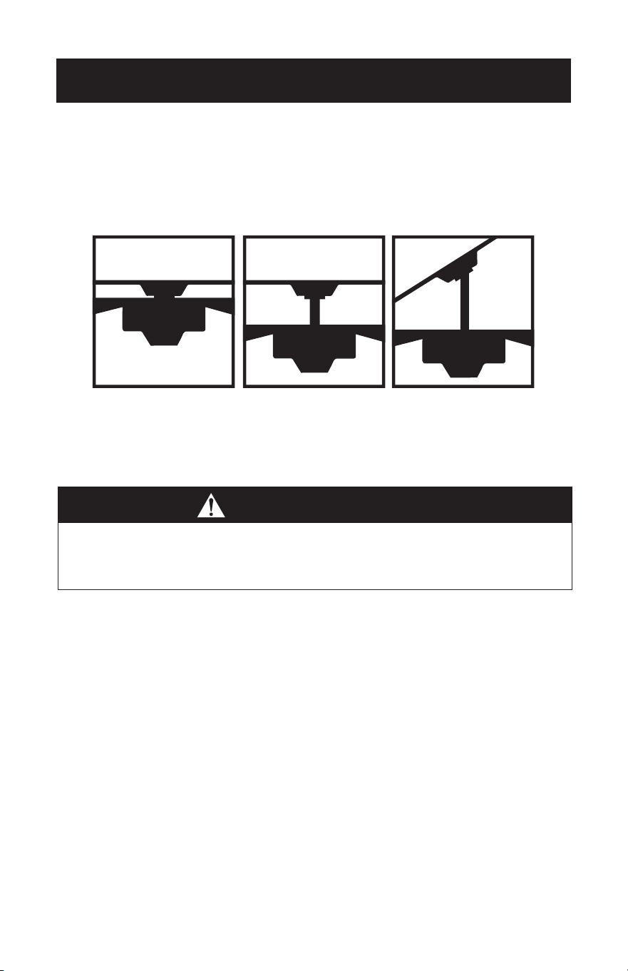
Page 64
CONFIGURACIÓN Y USO
CARACTERÍSTICAS
Instalación con varilla
de extensión
Para techos normales
Instalación en techo
abovedado
Puede requerir una
varilla de extensión
más larga (se vende
por separado)
PRECAUCIÓN
Para reducir el riesgo de lesiones personales, el ventilador debe instalarse de modo
que las aspas estén a una altura superior a 7 pies (2,1 metros) sobre el piso.
Este ventilador está diseñado para uso en interiores.
Instalación
al ras
Para techos normales

CONFIGURACIÓN Y USO
Page 65
PREPARACIÓN PARA LA INSTALACIÓN
1. Desempaque e inspeccione el ventilador con cuidado para asegurarse de que todo
el contenido esté incluido. Desconecte la corriente en la caja de fusibles para evitar
posibles descargas eléctricas.
2. Use una caja de salida de metal adecuada para el soporte del ventilador
(clasificada para 35 lb (15,9 kg)). Antes de conectar el ventilador a la caja de salida,
asegúrese de que la miste esté fijada de manera segura por al menos dos puntos a
un soporte estructural del techo (una caja suelta hará que el ventilador oscile).
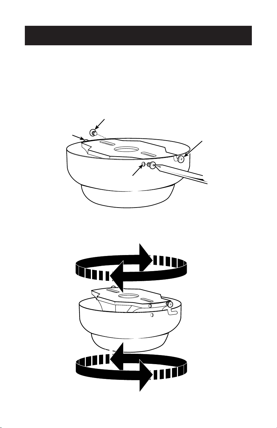
Page 66
INSTALACIÓN DEL SOPORTE DE MONTAJE
3. Retire los tornillos de los dos orificios de acoplamiento (2) en el dosel. Afloje (no
quite) los tornillos en las ranuras de acoplamiento (1) en el dosel. Gire el soporte de
montaje y retírelo del dosel.
2
1
1
2
2
1
1
2
CONFIGURACIÓN Y USO
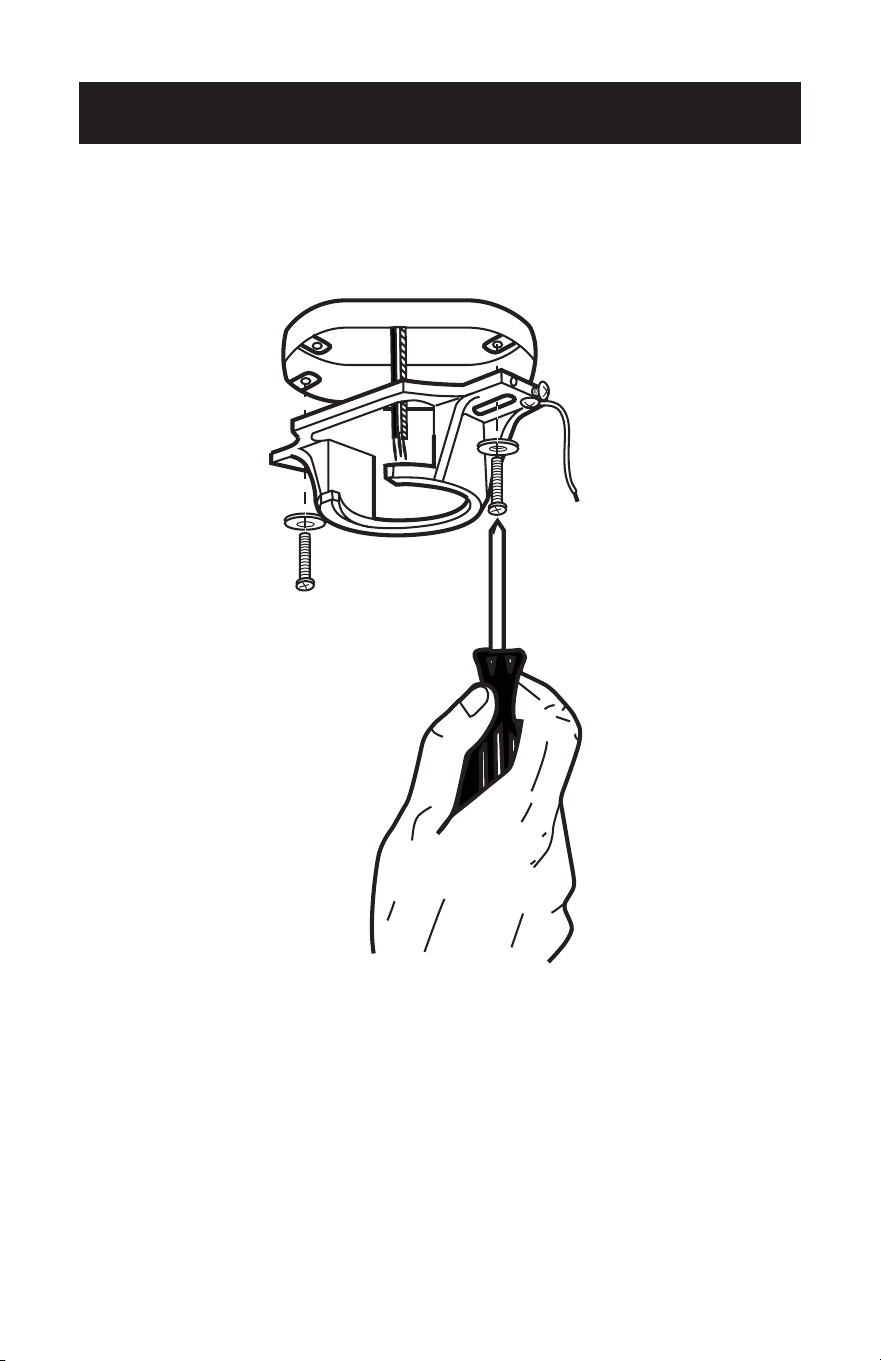
Page 67
CONFIGURACIÓN Y USO
4. Instale el soporte de montaje en la caja de salida en el techo utilizando los tornillos
y arandelas provistos con la caja de salida.

Page 68
CONFIGURACIÓN Y USO
5. Elija una OPCIÓN DE MONTAJE (Mostrado en la página 8):
OPCIÓN DE INSTALACIÓN AL RAS
Para instalar al ras, retire los tornillos del dosel y vuelva a colocar los 3 tornillos para
fijar el dosel a la carcasa del motor como se muestra.
Complete las opciones de cableado como se muestra en la página 15. Se requerirán
dos personas para completar esta instalación. Alguien tendrá que sostener el dosel y
la carcasa del motor mientras se conectan los cables.
Si está instalando un ventilador de techo con un receptor de control remoto, vaya a
la página 16, paso 12. Si no necesita incluir un receptor de control remoto, proceda a
asegurar el ventilador al techo como se muestra en la página 17, paso 13.
OPCIÓN CON VARILLA DE
EXTENSIÓN NORMAL
6. Retire el pasador de sujeción (1) y el
pasador transversal (2) de la varilla de
extensión (3). Diríjase a INSTALACIÓN
DE LA VARILLA DE EXTENSIÓN en la
página 13, paso 7.
1
2
3
Screws
Motor
Housing
Canopy

Page 69
CONFIGURACIÓN Y USO
INSTALACIÓN DE LA VARILLA DE EXTENSIÓN
7. Inserte los cables del motor a través de la varilla de extensión seleccionada e inserte
la varilla dentro del acoplamiento de la varilla de extensión. Asegúrese de alinear
el orificio en la varilla con el orificio en el acoplamiento de la varilla de extensión.
Instale el pasador transversal (1) retirado en el paso 6 a través del acoplamiento y
la varilla de extensión. Inserte el pasador de sujeción (2) en el pasador transversal
hasta que encaje en su lugar. Apriete los tornillos de fijación (3) en el acoplamiento.
Deslice la cubierta de acoplamiento (4) y el dosel en la varilla de extensión sobre la
cubierta de acoplamiento. PROCEDA A LA PÁGINA 14, PASO 8.
1
4
3
2
Downrod Coupling
1
4
3
2
Downrod Coupling
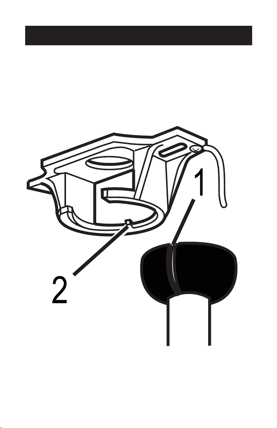
Page 70
MONTAJE
8. Levante con cuidado el conjunto del ventilador hacie el soporte de montaje. Gire
el ventilador hasta que la muesca en la bola de la varilla de extensión (1) encaje en
el caballete en el soporte de montaje (2). Esto permitirá el cableado con las manos
libres para la instalación del ventilador en la varilla de extensión.
NOTA: Si está instalando el ventilador al ras, necesitará ayuda para sostener el
ventilador mientras hace el cableado.
CONFIGURACIÓN Y USO
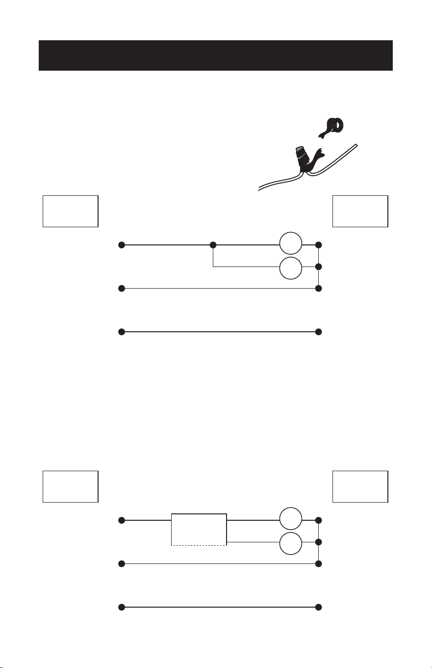
Page 71
CONFIGURACIÓN Y USO
OPCIONES DE CABLEADO PARA BCF5211 CON
INTERRUPTOR DE CADENA
9. Para asegurarse de que no haya cables pelados expuestos
después de hacer las conexiones, se recomienda envolver
con cinta aislante alrededor de cada conector para evitar
que se desconecte.
Use los conectores de cable suministrados para conectar los cables.
OPCIONES DE CABLEADO PARA BCF5211R
CON CONTROL REMOTO
10. Los interruptores de frecuencia en su receptor y transmisor han sido configurados
de fábrica. Vuelva a verificar para asegurarse de que los interruptores en el
transmisor y el receptor estén en la misma posición, cualquier combinación de
ajustes operará el ventilador siempre que el transmisor y el receptor estén en la
misma posición.
Use los conectores de cable suministrados para conectar los cables.
BLK BLK
BLUE
Fan
Light
GREEN
WHITE
REMOTE
RECEIVER
Live
Neutral
Ground
FANCEILING
Live
Neutral
Ground
BLK BLK
BLUE
Fan
Light
GREEN
WHITE
FANCEILING
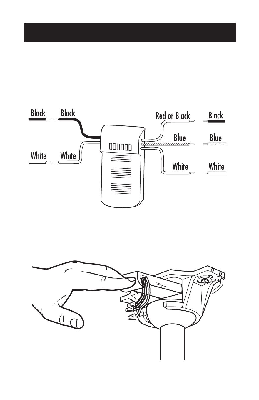
Page 72
11. Haga las conexiones de cableado desde el techo y el motor del ventilador al
receptor remoto como se muestra arriba. Conéctese usando conectores de cables
(provistos).
12. Una vez que el cableado se haya completado, inserte el receptor del control
remoto en la parte superior del soporte de montaje como se muestra. En las
instalaciones con varilla de extensión, estará en la parte superior de la bola de la
varilla de extensión.
Ceiling Fan
Ceiling Fan
CONFIGURACIÓN Y USO
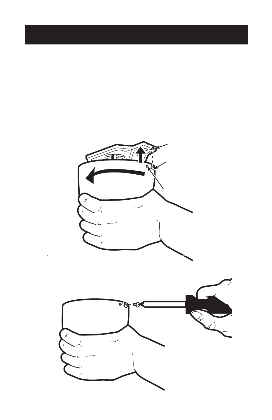
Page 73
CONFIGURACIÓN Y USO
ASEGURAR AL TECHO
13. El dosel tiene dos ranuras de acoplamiento (1) y dos orificios de acoplamiento
(2). Coloque ambas ranuras en el dosel directamente debajo y en línea con los
dos tornillos en el soporte de montaje (3). Levante el dosel, permitiendo que
los dos tornillos se deslicen en las ranuras de acoplamiento. Gire el dosel hasta
que los dos tornillos del soporte de montaje caigan en los huecos de la ranura.
Apriete los tornillos hasta que queden seguros. Instale dos tornillos en los orificios
correspondientes del dosel y apriételos para asegurar el dosel al soporte de
montaje.
NOTA: Para ventiladores con varilla de extensión, deslice el dosel hasta el soporte
de montaje.
2
3
1
2
3
1

Page 74
CONFIGURACIÓN Y USO
INSTALACIÓN DE LAS ASPAS
14. Fije la cuchilla al soporte de la cuchilla como se muestra.
Inserte el soporte de la cuchilla en la carcasa del motor del ventilador. Asegure cada
cuchilla con los tornillos provistos y arandelas de seguridad como se muestra. Gire
ligeramente cada cuchilla después de la instalación y repita el mismo paso para cada
cuchilla.
Hex Nut
Small Lock Washer
Washers
Blade Bracket
Blade Bracket Screws

Page 75
INSTALACIÓN DE LUMINARIAS
15. Instalar 2 bombillas Tipo A-19, 60W máx. (no incluidas).
16. Ubique las hendiduras en el cuello del vidrio (2) y alinéelo con las protuberancias
del juego de luces (1). Levante el vidrio permitiendo que las protuberancias se
acoplen a las hendiduras del vidrio y gire el vidrio en el sentido de las agujas del
reloj para bloquearlo en su lugar.
Si su modelo tiene interruptores con cadena, puede conectar las extensiones con los
tiradores.
CONFIGURACIÓN Y USO
1
2
1
2

Page 76
CONFIGURACIÓN Y USO
17. El modelo BCF5211R viene con un soporte para almacenar su control remoto.
Monte el soporte del control remoto en la pared con los tornillos provistos. Si no
desea atornillar el soporte del control remoto en la pared, puede comprar un algún
adhesivo en su ferretería local.
0
1
2 3

Page 77
OPERACIÓN DEL CONTROL REMOTO
PARA EL MODELO BCF5211R
Botón en el control remoto:
1 Velocidad de ventilador alta
2 Velocidad de ventilador media
3 Velocidad de ventilador baja
0 Ventilador apagado
Luz encendida/apagada
Atenuador de luz
NOTA: Mantenga presionado para aumentar o disminuir la luz. La luz tiene una
función de memoria para que la luz permanezca en el mismo brillo que la
última vez que se apagó.
1. Instalación de las baterías (baterías no incluidas)
(1) Abra la tapa del compartimiento de las baterías.
(2) Inserte 2 baterías “AA” como se muestra a continuación.
(3) Deslice para volver a colocar la tapa del compartimiento de las baterías.
NOTA: Ase batarías alcalinas de tamaño “AA”. No utilice baterías recargables.
CONFIGURACIÓN Y USO
0
1
2 3
–+
Remote Control
Battery Battery Cover

CONFIGURACIÓN Y USO
FUNCIONAMIENTO
El interruptor deslizante controla la dirección, hacia adelante o hacia atrás.
Clima cálido - interruptor en la posición izquierda
El ventilador gira en sentido antihorario. Un flujo de aire hacia abajo crea un efecto de
enfriamiento como se muestra en la ilustración A.
Clima frío - interruptor en la posición derecha (ver imagen).
El ventilador gira en el sentido de las agujas del reloj. Un flujo de aire ascendente aleja
el aire caliente del área del techo como se muestra en la ilustración B (Esta función se
usa generalmente en el invierno).
NOTA: Apague y espere a que el ventilador se detenga antes de cambiar la
configuración del interruptor deslizante de configuración de flujo directo/
reverso.
OPERACIÓN DE INTERRUPTORES DE CADENA
Si su modelo viene equipado con interruptores de cadena, una cadena controla la luz
(encendido / apagado). La otra cadena controla la velocidad del ventilador.
1. El primer tirón pondrá el ventilador en velocidad alta.
2. El segundo tirón pondrá el ventilador en velocidad media.
3. El tercer tirón pondrá el ventilador en velocidad baja.
4. El cuarto tirón apagará el ventilador.
Page 78

Page 79
LIMPIEZA + MANTENIMIENTO
1. Debido al movimiento natural del ventilador, algunas conexiones pueden aflojarse.
Verifique las conexiones de soporte, los enganches y los accesorios de las aspas dos
veces al año. Asegúrese de que estén seguros y ajustados.
2. Limpie su ventilador periódicamente para ayudar a mantener su apariencia de
nuevo a lo largo de los años. No utilice agua al limpiar. Esto podría dañar el motor o
la madera, o posiblemente causar una descarga eléctrica.
3. Use solamente un cepillo suave o un paño sin pelusa para evitar rayar el acabado. El
chapado está sellado con un recubrimiento de laca para minimizar la decoloración
o el deslustre.
4. No hay necesidad de engrasar su ventilador. El motor tiene cojinetes lubricados
permanentemente.
5. Para cambiar (2) las baterías alcalinas tamaño “AA”, consulte la página 21.
6. Para cambiar las bombillas, vea la página 19.
LIMPIEZA + MANTENIMIENTO
Page 79

CONFIGURACIÓN Y USO
ANTES DE LLAMAR AL SERVICIO TÉCNICO
SI EL ELECTRODOMÉSTICO NO FUNCIONA:
Compruebe si hay un fusible quemado o un disyuntor principal disparado. Si éstos
funcionan correctamente, pruebe el enchufe con otro electrodoméstico.
SI NINGUNO DE LOS RESULTADOS ANTERIORES RESUELVE EL PROBLEMA,
COMUNÍQUESE CON UN TÉCNICO CALIFICADO. NO INTENTE AJUSTAR O
REPARAR EL ELECTRODOMÉSTICO USTED MISMO.
IMPORTANTE
NO DEVUELVA ESTE PRODUCTO A LA TIENDA
Si tiene un problema con este producto, entre en contacto con
W Appliance Co. Centro da Satisfacción de Cliente a travése del
844-299-0879 o service@appliance.com.
COMPROBANTE CON FECHA DE COMPRA, NÚMERO DE
MODELO Y NÚMERO DE SERIE NECESARIOS PARA EL
SERVICIO DE GARANTÍA
Page 80
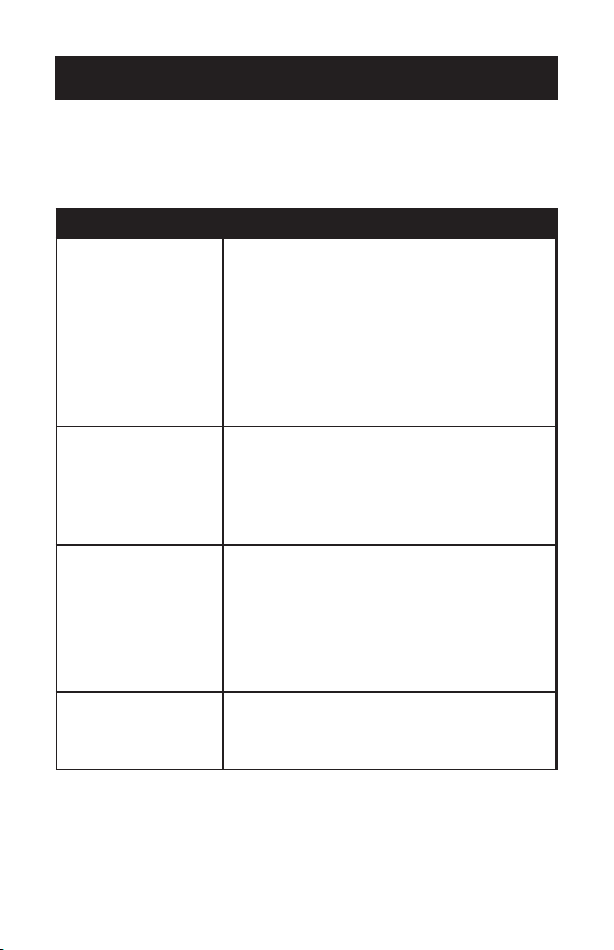
SOLUCIÓN DE PROBLEMAS Y GARANTÍA
PROBLEMA SOLUCIÓN POSIBLE
Si el ventilador no se inicia
1. Verifique los fusibles del circuito principal y secundario o los
interruptores.
2. Verifique las conexiones de los cables según las páginas de
instalación aplicables 11-16. PRECAUCIÓN: asegúrese de que
la corriente principal esté apagada.
3. Asegúrese de que el interruptor de flujo directo/reverso
esté firmemente en la posición derecha o izquierda. El
ventilador no funcionará cuando el interruptor esté en el
medio.
4. Si el ventilador aún no se enciende, contacte a un
electricista calificado. No intente solucionar problemas en
las conexiones eléctricas internas usted mismo.
5. Si se usa el control remoto, verifique las baterías.
Si el ventilador hace mucho
ruido
1. Verifique para asegurarse de que todos los tornillos en
la carcasa del motor estén ajustados (no demasiado
apretados).
2. Verifique que los tornillos que sujetan el soporte de las
aspas del ventilador al motor estén apretados.
3. Permita un período de “asentamiento” de 24 horas. La
mayoría de los ruidos asociados con un nuevo ventilador
desaparecerán después de este período.
Si el ventilador se tambalea
1. Verifique que todas las aspas estén firmemente atornilladas
a sus soportes.
2. Verifique que todos los soportes de las aspas estén bien
apretados al motor.
3. Asegúrese de que el dosel y el soporte de montaje estén
bien ajustados a la viga del techo.
4. Si la oscilación de las aspas todavía es perceptible, el
intercambio de dos aspas adyacentes (lado a lado) puede
redistribuir el peso y posiblemente dar como resultado una
operación más suave.
Si la luz no funciona
1. Verifique si hay bombillas defectuosas.
2. Verifique que las conexiones de cables en la caja del
interruptor estén conectadas.
3. Si el kit de luces aún no funciona, comuníquese con un
electricista calificado para obtener asistencia.
Solucione su problema utilizando el cuadro a continuación. Si el electrodoméstico
aún no funciona correctamente, comuníquese con el centro de servicio al cliente de
W Appliance Co. Los clientes nunca deben solucionar problemas de componentes
internos.
Page 81

SOLUCIÓN DE PROBLEMAS Y GARANTÍA
GARANTÍA LIMITADA
Cualquier reparación, reemplazo o servicio
de garantía, y todas las preguntas sobre este
producto deben dirigirse a W Appliance Co. al
844-299-0879 desde EE.UU. O Puerto Rico.
W Appliance Co. garantiza al comprador original que
el producto estará libre de defectos de material, piezas
y mano de obra durante el período designado para
este producto. La garantía comienza el día en que se
compra el producto y cubre hasta un período de 1 año
(12 meses) por mano de obra / 1 año (12 meses) por
piezas (solo defectos de fabricación).
W Appliance Co. acepta que, a su elección,
reemplazará el producto defectuoso con una unidad
nueva o remanufacturada equivalente a su compra
original durante el período de garantía.
Exclusiones: esta garantía no se aplica a lo siguiente:
1. Si la apariencia o el exterior de
el producto ha sido dañado o cambiado,
alterado o modificado en diseño o
construcción.
2. Si el número de serie original del
producto ha sido alterado o eliminado o
no puedeser fácilmente determinado.
3. Si está dañado debido a una sobrecarga
de la línea eléctrica, daño por parte
del usuario al cable de alimentación de
CA o conexión a una fuente de voltaje
incorrecta.
4. Si el daño se debe a un mal uso general,
accidentes o actos de Dios.
5. Si los intentos de reparación son
realizados por agentes de servicio no
autorizados, el uso de piezas que no
sean piezas originales o piezas obtenidas
de personas que no sean empresas de
servicios autorizadas.
6. A unidades que han sido transferidas
del propietario original.
7. A productos que han sido comprados
como reacondicionados, como nuevos,
de segunda mano, en términos de “tal
como es” o “venta final”.
8. A los productos utilizados en un entorno
comercial o de alquiler.
9. A productos utilizados en condiciones
distintas a las ordinarias de uso
doméstico normal o usado de otra
manera que no sea de acuerdo con las
instrucciones provistas.
10. A los daños por las llamadas al servicio
por instalaciones inadecuadas.
11. A costos de transporte y envío
asociados con el reemplazo de la
unidad.
12. A llamadas de servicio para instruirlo
sobre cómo usar su producto.
13. Llamadas de servicio para reparar o
reemplazar el fusible de la casa, reinicie
el disyuntor o corrija el cableado de
la casa.
LA REPARACIÓN O EL REEMPLAZO SEGÚN LO
DISPUESTO BAJO ESTA GARANTÍA ES EL RECURSO
EXCLUSIVO DEL CLIENTE; W Appliance Co. NO SERÁ
RESPONSABLE POR NINGÚN DAÑO INCIDENTAL
O CONSECUENCIAL POR INCUMPLIMIENTO DE
CUALQUIER GARANTÍA EXPRESA O IMPLÍCITA DE
ESTE PRODUCTO, EXCEPTO EN LA MEDIDA EN
QUE LO PROHÍBA LA LEY APLICABLE. CUALQUIER
GARANTÍA IMPLÍCITA DE COMERCIABILIDAD O
IDONEIDAD PARA UN PROPÓSITO PARTICULAR
SOBRE ESTE PRODUCTO TIENE UNA DURACIÓN
LIMITADA A LA DURACIÓN DE ESTA GARANTÍA.
Algunos estados no permiten la exclusión o
limitaciones de daños incidentales o consecuentes,
o limitaciones en la duración de la garantía. En estos
casos, las exclusiones o limitaciones anteriores pueden
no aplicarse en su caso. Esta garantía le otorga
derechos legales específicos, y también puede tener
otros derechos que varían de estado a estado.
Obtención de servicio: para obtener servicio,
documentación del producto, suministros o
accesorios, llame al
844-299-0879 para crear un ticket de cambio/
reparación. Asegúrese de proporcionar la fecha de
compra, el número de modelo y una breve descripción
del problema. Nuestros representantes de servicio
al cliente se comunicarán con usted o enviarán
instrucciones detalladas de devolución.
W Appliance Co. no garantiza que el electrodoméstico funcionará
correctamente en todas las condiciones ambientales, y no ofrece
garantía y representación, implícita o explícita, con respecto a la
calidad, el rendimiento, la comerciabilidad o la idoneidad para
un fin en particular distinto del propósito identificado dentro
de este manual de usuario. W Appliance Co. ha hecho todos los
esfuerzos posibles para garantizar que este manual del usuario
sea preciso y se exime de toda responsabilidad por cualquier
inexactitud u omisión que pueda haber ocurrido. La información
en este manual del usuario está sujeta a cambios sin previo aviso
y no representa un compromiso por parte de W Appliance Co. W
Appliance Co. se reserva el derecho de realizar mejoras en este
manual del usuario y/o en los productos descritos en este manual
del usuario en cualquier momento sin previo aviso. Si encuentra
información en este manual que es incorrecta, engañosa o
incompleta, comuníquese con nosotros al 844-299-0879.
W Appliance Co.
1356 Broadway
New York, NY 10018
Page 82

Este dispositivo cumple con el apartado 15 de las Normas de la FCC. El
funcionamiento de este dispositivo está sujeto a las dos condiciones siguientes:
(1) este dispositivo no causa interferencias perjudiciales, y (2) este dispositivo
debe aceptar cualquier interferencia que reciba, incluidas aquellas que puedan
causar un funcionamiento no deseado. Este equipo ha sido sometido a las pruebas
pertinentes y cumple con los límites establecidos para un dispositivo digital de clase
B, conforme al apartado 15 de las reglas de la FCC. Estos límites se han establecido
con el fin de ofrecer una protección razonable frente a interferencias perjudiciales
en una instalación residencial. Este equipo genera, utiliza y puede radiar energía de
radiofrecuencia, y si no se lo instala y utiliza según las instrucciones, puede causar
interferencias perjudiciales para las comunicaciones por radio. Sin embargo, no existe
garantía de que las interferencias no puedan producirse en una instalación particular.
Si este equipo causa interferencia dañina a la recepción de radio o televisión, lo cual
puede determinarse apagando y encendiendo el equipo, se recomienda al usuario
que intente corregir la interferencia mediante una o más de las siguientes medidas:
a) Reorientar o reubicar la antena de recepción. b) Aumente la separación entre el
equipo y el receptor. c) Conecte el equipo a un tomacorriente diferente del que está
conectado el receptor. d) Consulte con el distribuidor o un técnico experimentado en
radio/TV para obtener ayuda.

Page 84
BLACK & DECKER, BLACK+DECKER, the BLACK & DECKER and
BLACK+DECKER logos and product names and the orange and black color
scheme are trademarks of The Black & Decker Corporation, used under license.
All rights reserved.
Product in this box may differ slightly from that pictured. Does not affect
function. Not all accessories shown in photography are included in this
package.
Imported by W Appliance, Inc., 1356 Broadway, New York, NY 10018
Les logos et les noms de produits BLACK & DECKER, BLACK+DECKER, BLACK
& DECKER et BLACK+DECKER ainsi que les couleurs orange et noire sont
des marques de commerce de The Black & Decker Corporation, utilisées sous
licence. Tous droits réservés.
Le produit dans cette boîte peut différer légèrement de celui illustré. N’affecte
pas la fonction. Pas tous les accessoires présentés dans la photographie sont
inclus dans ce paquet
Importé par W Appliance, Inc., 1356 Broadway, New York, NY 10018
BLACK & DECKER, BLACK+DECKER, los logos BLACK & DECKER y
BLACK+DECKER y los nombres de productos y el esquema de color naranja y
negro son marcas comerciales de The Black & Decker Corporation, utilizadas
bajo licencia. Todos los derechos reservados.
El producto en esta caja puede diferir levemente del de la imagen. No afecta
su función. No todos los accesorios que se muestran en la fotografía están
incluidos en este paquete.
March 2018 Printed in China
Imprimé en Chine
Impreso en China