MRX-4SEN2
Owner’s Manual
Total Control
MRX-4SEN2
Owner’s Manual
Total Control
MRX-4SEN2
Owner’s Manual
Rev 1.0
Technical Suppor t
Toll Free: 800-904-0800
Main: 914-835-4484
techsupport@urc-automation.com
H o u r s : 9 : 0 0 a m - 5 : 0 0 p m E S T M - F
Table of Contents
Introduction ........................................................................................................................................................................................................................................................................1
Front Panel Description ...................................................................................................................................................................................................................................................2
Rear Panel Description ....................................................................................................................................................................................................................................................3
Bottom Panel Description................................................................................................................................................................................................................................................4
Installing the MRX-4SEN2 ...............................................................................................................................................................................................................................................5
Wireless Setup ..................................................................................................................................................................................................................................................................6
Specifications ....................................................................................................................................................................................................................................................................9
Limited Warranty Statement............................................................................................................................................................................................................................................9
1
Total Control
MRX-4SEN2
Owner’s Manual
Introduction
The MRX-4SEN2 Sensor Extender is designed to meet the needs of residential or
small commercial environments.
Only Total Control software, products, and user interfaces are supported by this
powerful device.
Features and Benefits
• The MRX-4SEN2 utilizes the network (wired or wireless) for a more stable
communication to the Total Control System that is less susceptible to
interference and more reliable. This grants you the flexibility to install it
virtually anywhere in the project.
• Add one or more MRX-4SEN2 throughout your home or ofce to
detect changes in a connected sensor, which may be used to
trigger system events.
• The small size of the MRX-4SEN2 allows it to easily t behind equipment or
into places where a traditional base station would not.
Parts List
The MRX-4SEN2 Sensor Extender includes:
• 1x MRX-4SEN2 Sensor Extender
• 1x AC Power Adapter
• 4x Mounting Screws
• Mounting Plate
2
Total Control
MRX-4SEN2
Owner’s Manual
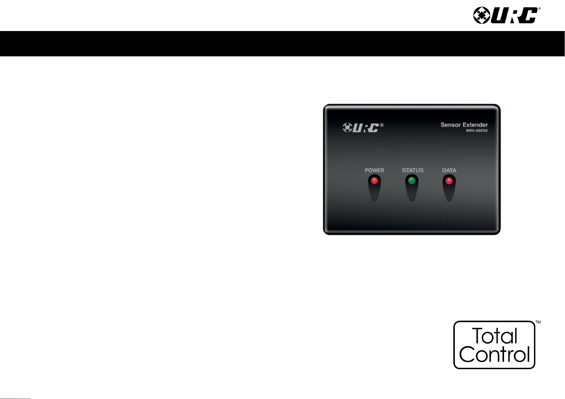
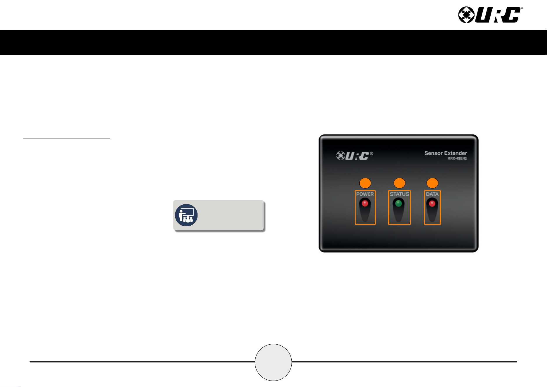
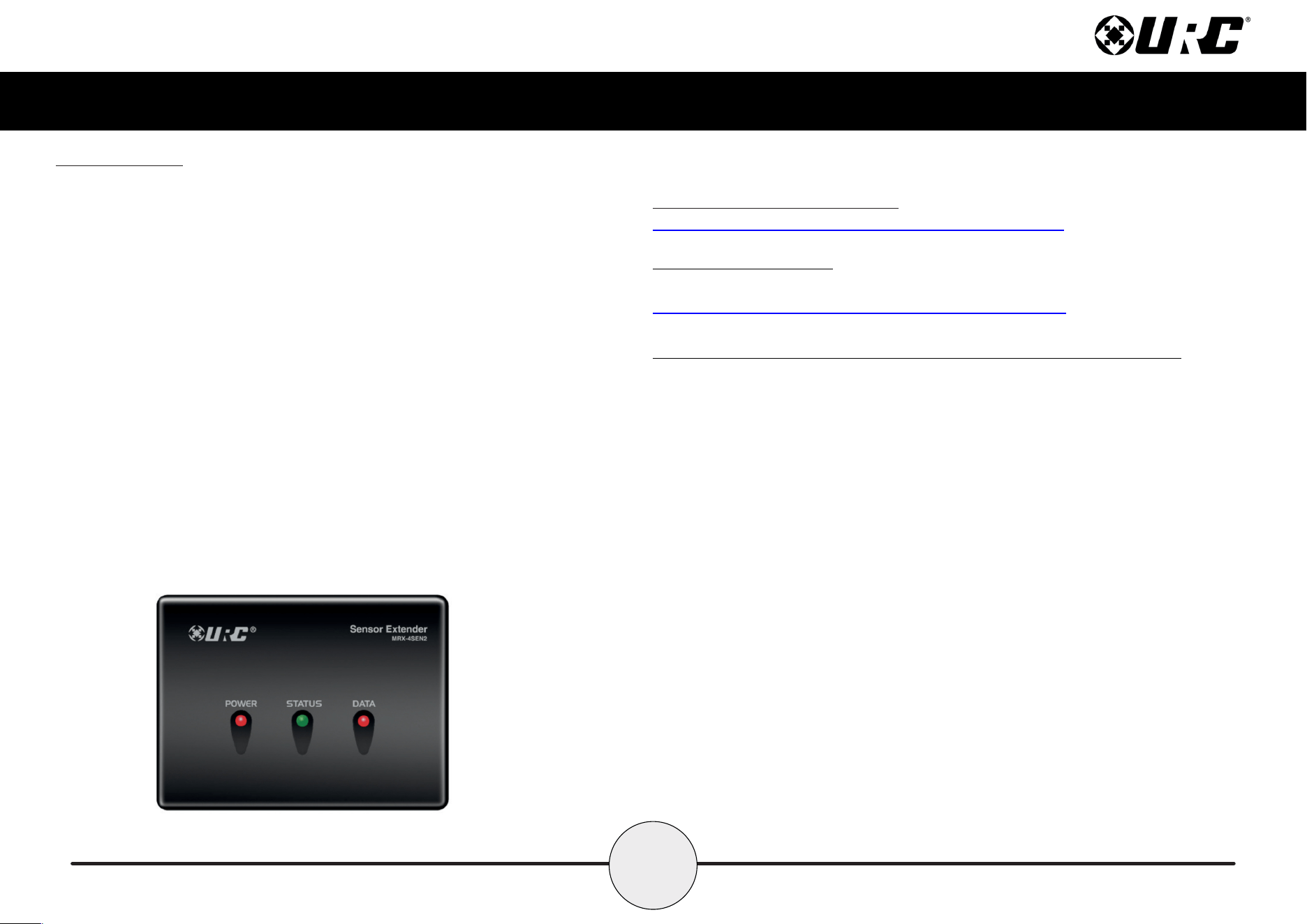
Front Panel Description
The front panel of the MRX-4SEN2 Sensor Extender displays the following information:
1. Power LED: Indicates the device has power.
2. Status LED: Indicates three (3) possible states:
■ Green: Good signal strength.
■ Red: Poor signal strength.
■ Off: No connection.
3. Data LED: Indicates the device is transmitting IR data.
When connected via
Ethernet, the status LED
does not illuminate.
1 2 3
3
Total Control
MRX-4SEN2
Owner’s Manual
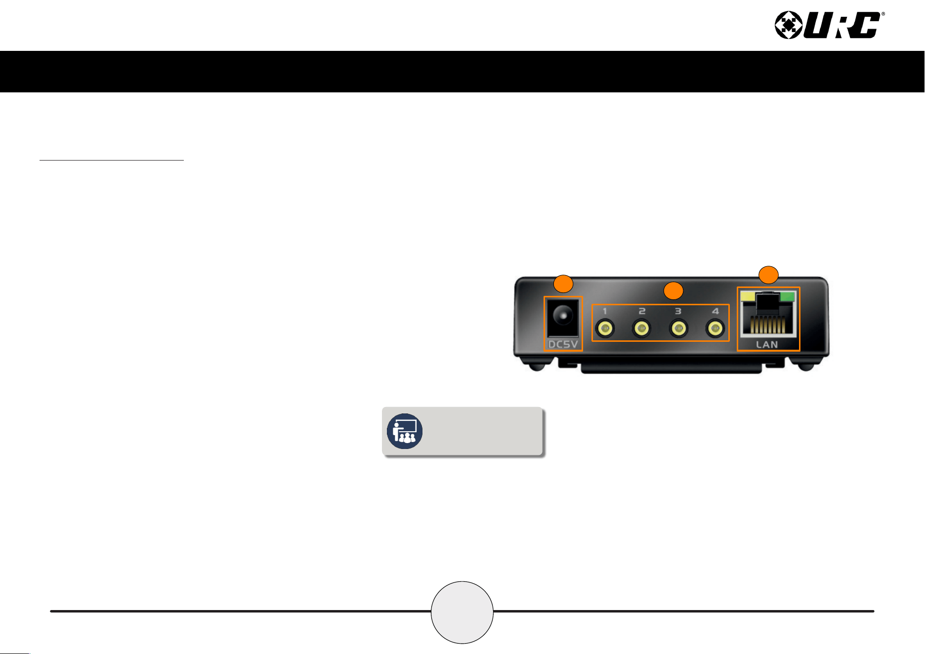
Rear Panel Description
The rear panel of the MRX-4SEN2 Sensor Extender displays the following information:
1. DC 5V: Connect the supplied power adapter to this port, the Power LED
becomes solid blue when the device has received power.
2. Sensor Inputs: Connect the sensor’s 3.5mm plug to an available port. The
following URC sensors, with their respective model numbers, are
compatible with the MRX-4SEN2:
■ Voltage Sensor SEN-VOLT
■ Video Sensor SEN-VID
■ Contact Closure Sensor SEN-CCLS
■ Light Sensor SEN-LITE
■ Current Sensor (Magnetic Field) SEN-CMF
■ Audio Sensor SEN-AUD
3. Ethernet: If a wired connection is needed, this port uses a standard Ethernet
(RJ-45) plug to communicate via the local area network (LAN).
1
2
3
To connect to Wi-Fi, an
initial Ethernet connection
must be made rst.
4
Total Control
MRX-4SEN2
Owner’s Manual
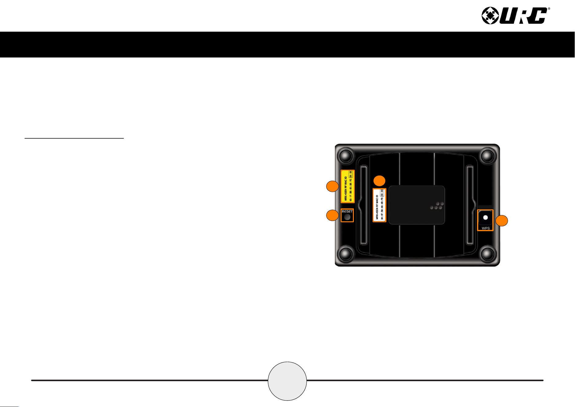
Bottom Panel Description
The bottom panel of the MRX-4SEN2 Sensor Extender displays the following information:
1. Serial Number Sticker: The ZIGBEE Address (16 characters) identies this
wireless device when connected to the network.
2. MAC Number Sticker: The serial number, located at the bottom of the unit,
uniquely identies the product.
3. WPS (Wi-Fi Protected Setup): Functions with other wireless devices (routers,
wireless access points, etc.) to provide a simplified method of connection to the
network. Press this button in conjunction with the WPS button found on your other
wireless devices to establish.
4. Reset Button: Turns the unit OFF then ON again, and reconnects to the network.
2
4
1
3
5
Total Control
MRX-4SEN2
Owner’s Manual
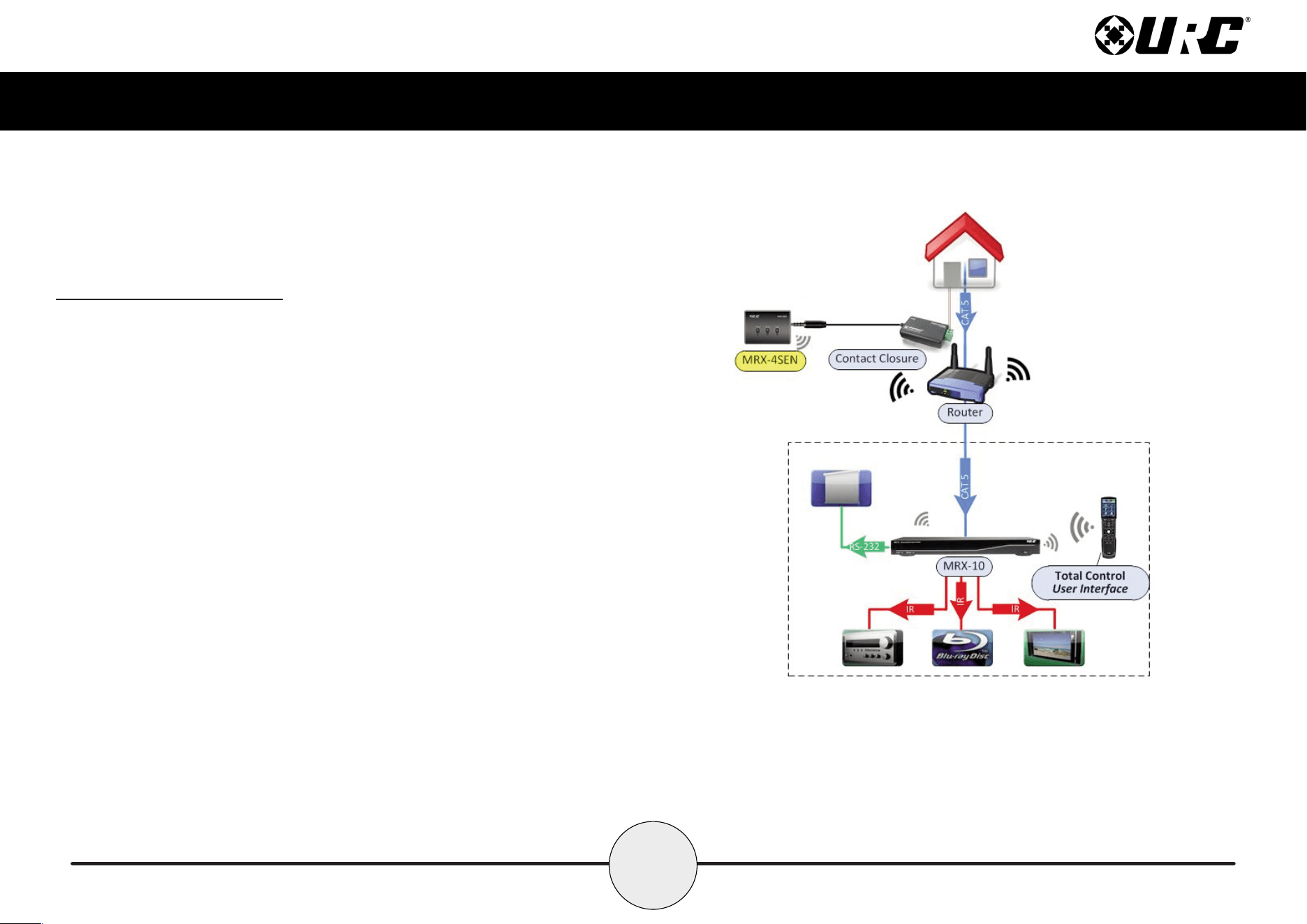
Installing the MRX-4SEN2
The MRX-4SEN2 Sensor Extender can be installed almost anywhere in the home.
Once physically installed, it requires programming by a certified URC integrator
in order to function properly.
Connect the 3.5mm sensor plug to the rear of the MRX-4SEN2. When a change in
the sensor’s state is detected, the MRX-4SEN2 sends a signal to the MRX Advanced
Network System Controller and triggers a series of commands.
This home network example showcases a voltage sensor connected to the home’s
doorbell and the MRX-4SEN2. Whenever the door bell is pressed, a signal is sent
over URC’s RF 2.4GHz to the MRX Advanced Network System Controller. The MRX
unit triggers a series of commands or an event to gain your attention. A
programmed event, such as Watch Movie/TV, may pause the movie, mute the audio
and display the front door’s video camera.
6
Total Control
MRX-4SEN2
Owner’s Manual
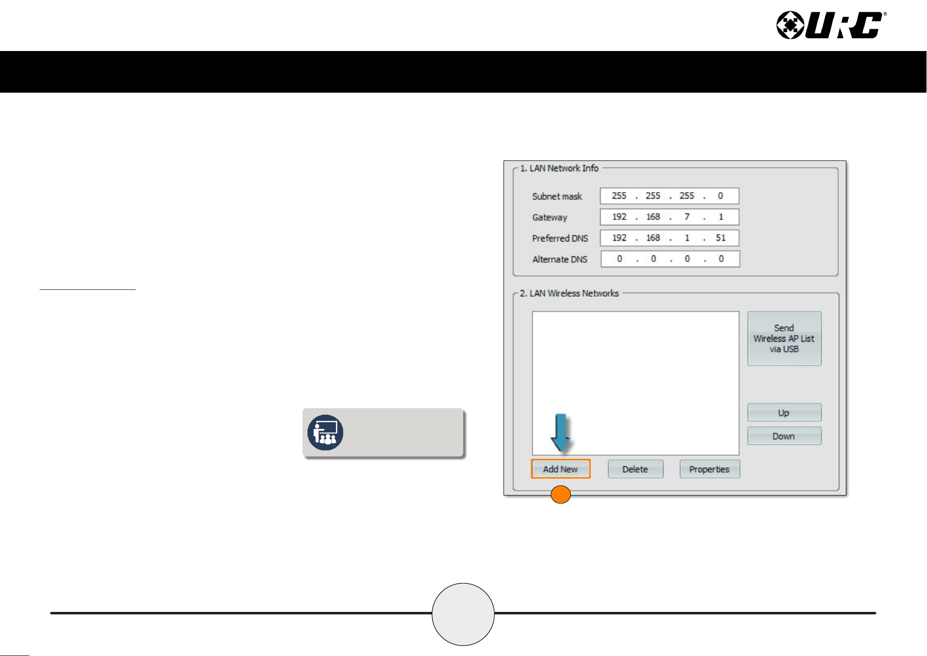
Wireless Setup
The key feature added to the MRX-4SEN2 is adding Wi-Fi connectivity to an already
brilliant sensor expander. Wi-Fi connection makes it simple to install the device in
difcult to reach locations of the home.
1. Go to Step 6: Network Setup and select Add New.
1
To connect to Wi-Fi, an
initial Ethernet connection
must be made rst.
7
Total Control
MRX-4SEN2
Owner’s Manual
2
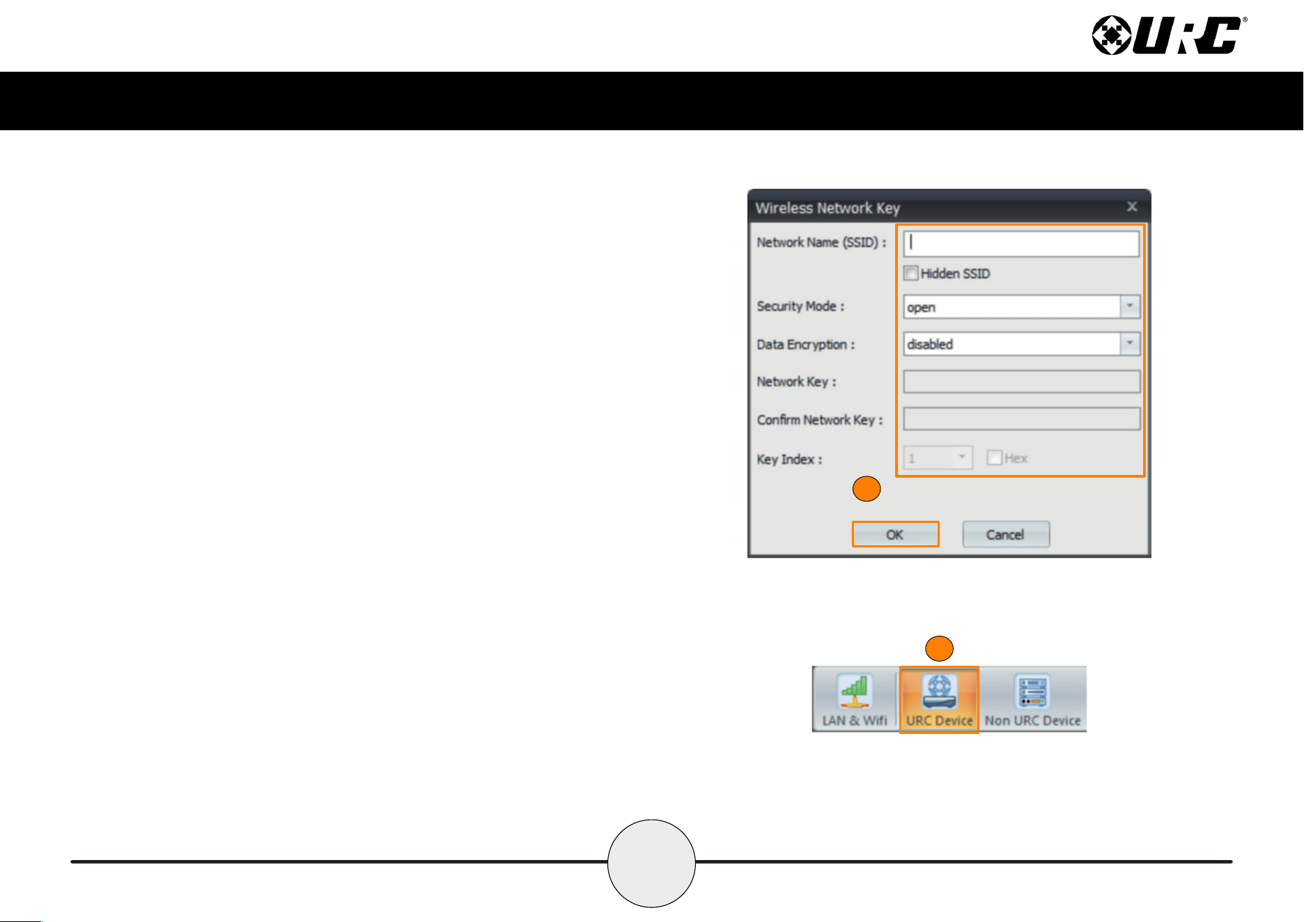
2. Fill out the wireless network information in the Wireless Network Key
window. Select OK when nished.
3. Select Save, located below 2. LAN Wireless Networks.
4. Select URC Device from the sub-menu in Step 6.
5. Discover the MRX-4SEN2 using the method for all URC network devices.
4
8
Total Control
MRX-4SEN2
Owner’s Manual
6
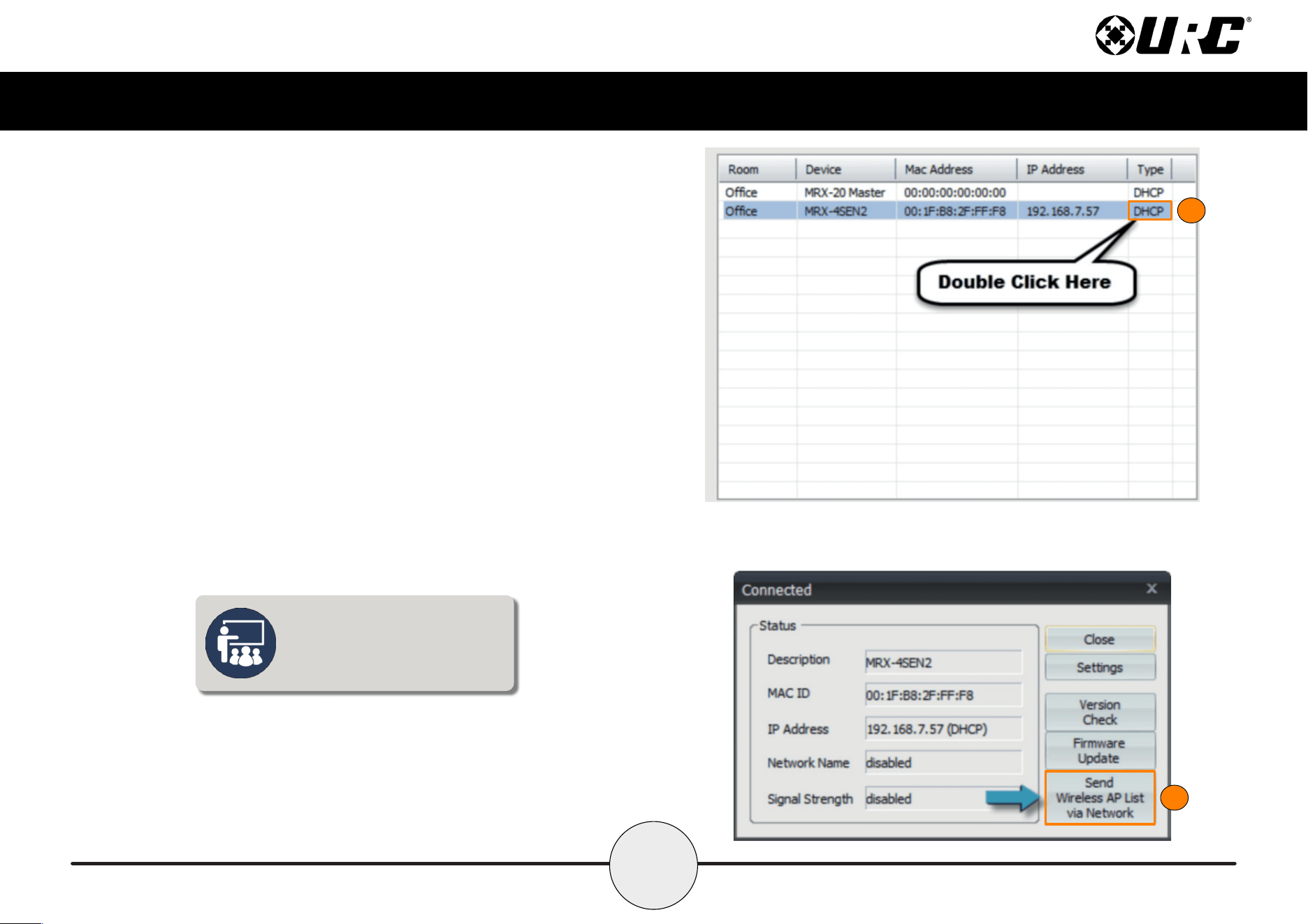
6. Highlight the MRX-4SEN2 and double-click on the area that reads DHCP.
7. Select Send Wireless AP List via Network.
8. Unplug the Ethernet cable from the back of the MRX-4SEN2 unit.
The MRX-4SEN2 connects to Wi-Fi
automatically after the Wireless AP
list has been downloaded and the
Ethernet cable has been removed.
7
9
Total Control
MRX-4SEN2
Owner’s Manual
Specifications
Sensor: Four sensor ports support Video, Current, Contact Closure,
Ambient Light, Audio, and Voltage sensors from URC.
Network: One 10/100/1000M RJ45 Ethernet port (two LED indicators)
RF Range (Radio Frequency): 50 to 100 feet, depending upon the
environment
RF Frequency: 2.405 ~ 2.480 GHz
Weight: 2.98oz
Size: 3.74” X 2.7” X 1.1”
Power: 12V DC 1A
Limited Warranty Statement
https://www.urc-automation.com/legal/warranty-statement/
End User Agreement
The terms and conditions of the End User Agreement available at
https://www.urc-automation.com/legal/end-user-agreement/ shall apply.
Federal Communication Commission Interference Statement
This equipment has been tested and found to comply with the limits for a Class B
digital device, pursuant to part 15 of the FCC Rules. These limits are designed to
provide reasonable protection against harmful interference in a residential installation.
This equipment generates, uses and can radiate radio frequency energy and, if not
installed and used in accordance with the instructions, may cause harmful interference
to radio communications. However, there is no guarantee that interference will not
occur in a particular installation. If this equipment does cause harmful interference to
radio or television reception, which can be determined by turning the equipment off
and on, the user is encouraged to try to correct the interference by one more of the
following measures:
• Reorient or relocate the receiving antenna.
• Increase the separation between the equipment and receiver.
• Connect the equipment into an outlet on a circuit different from that to which
the receiver is connected.
• Consult the dealer or an experienced radio/TV technician for help.
10
Total Control
MRX-4SEN2
Owner’s Manual
Regulatory Information to the User
• CE conformity Notice Products with “CE” marking comply EMC Directive
2014/30/EU issued by the commission of the European Community.
1. EMC Directive
• Emission
• Immunity
• Power
• Declaration of Conformity
“Hereby, Universal Remote Control Inc. declares that this MRX-4SEN2 is in
compliance with the Essential requirements.”
Warning!
The manufacturer is not responsible for any Radio or TV interference caused by
unauthorized modications to this equipment.
Changes or modications not expressly approved by the manufacturer could void the
user's authority to operate the equipment.
