Loading ...
Loading ...
Loading ...
Basic Operation
DSO8000E Series HandHeld Oscilloscope User Manual 40
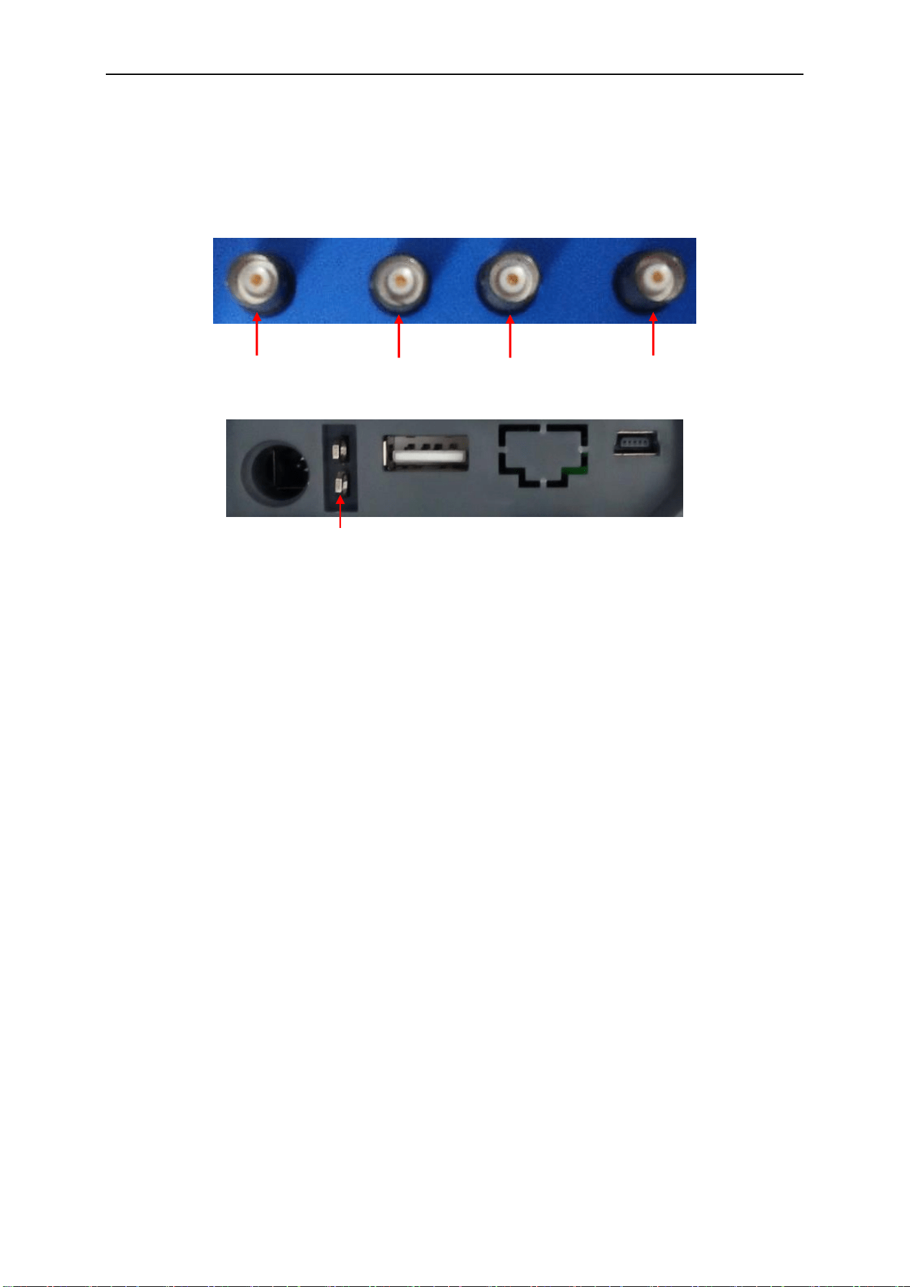
5.7 Signal Connectors
See the figure below to find the four signals connectors and a pair of metal electrodes at the
bottom of the oscilloscope panel.
1. CH1, CH2: Input connectors for waveform display, through which to connect and input the
signal to be measured.
2. OUTPUT: Waveform output BNC connector.
3. EXT TRIG/SYNC:
1) Input connector for an external trigger source, though with to connect and input the
external trigger signal.
2) Sync output connector for waveform signal.
4. Probe COMP: Voltage probe compensation output and ground, used to electrically match the
probe to the oscilloscope input circuit. The probe compensation ground and BNC shields
connect to earth ground and are considered to be ground terminals. To avoid damages, do not
connect a voltage source to any of these ground terminals.
PROBE COMP
CH1
OUTPUT
EXT TRIG/SYNC
CH2
Loading ...
Loading ...
Loading ...