Loading ...
Loading ...
Loading ...

16
Easy navigation in frequency domain
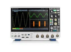
The R&S®MXO4 spectrum function has the familiar inter-
face of a spectrum analyzer. The spectrum setup dialog
offers basic spectrum analyzer controls such as start and
stop frequency and resolution bandwidth. In spectrum
mode, the R&S®MXO4 time domain settings are unaf-
fected. This makes navigation in the frequency domain
an easy task. The maximum FFT capture bandwidth cor-
responds to the R&S®MXO4 series bandwidth allowing a
quick overview of all the test device’s emissions from 0Hz
to 1.5GHz.
EMI DEBUGGING
The right setup with the right probes
Rohde & Schwarz offers the compact R&S®HZ-15 near-field
probe set, which is particularly helpful for EMI debugging
of embedded designs. The most compact probe in this set
allows capturing of near-field emissions from single circuit
lines. The R&S®HZ-15 covers the frequency range from
30MHz to 3GHz. With reduced sensitivity, it can also be
used below 30MHz. The optional R&S®HZ-16 preamplifier
provides 20dB gain in the frequency range from 100kHz
to 3GHz, in case higher sensitivity is needed.
Ultra-fast spectrum acquisitions for spurious spectrum events
The R&S®MXO4 series architecture is optimized both in
hardware and software to leverage the powerful ASIC
capabilities to deliver fast and responsive spectrum cap-
tures. This is critical in detecting random and spurious
emissions that are otherwise hidden due to the blind time
in acquisitions. The spectrum analysis is equipped with
max. hold, min. hold and average arithmetics to keep track
of spectrum events that occur during the testing. These
are important test receiver functions and now they come
standard on the R&S®MXO4 series spectrum function.
Gated spectrum for correlated time and frequency analysis
With the gated spectrum function, it is possible to restrict the spectrum analysis to a user-defined region of the captured
time domain signal. Excessive spectral emissions can be correlated to dedicated time periods in a signal. Typical appli-
cations include the correlation of unwanted emissions to fast switching edges in switched-mode power supplies or to
data transfers on bus interfaces. Having identified the problem, the design engineer can easily check the effectiveness
of different solutions such as blocking capacitors or reduced rise/fall times by observing the level change of the spectral
emission.
Loading ...
Loading ...
Loading ...
