
Product Brochure
Version 03.00
year
R&S®MXO4 SERIES
OSCILLOSCOPE
Next generation oscilloscope for accelerated insight
Oscilloscope innovation. Measurement confidence.
www.rohde-schwarz.com/product/MXO4

2
WHY USE THE R&S®MXO4?
►
World’s rst oscilloscope with update rate exceeding
4.5million waveforms per second
►
Industry-leading 12bit ADC at all sample rates
►
Industry-best 18bit architecture
►
Fastest and most accurate spectrum analysis in its class
►
Industry’s deepest standard memory of 400Mpoints per channel
►
Industry’s fastest trigger rearm time of 21ns
►
First in class to incorporate newer digital triggering technology
►
Industry’s most sensitive trigger of 1/10 000div
►
Best in class trigger jitter of <1ps
►
First oscilloscope with dual-path protocol analysis
►
First in class with R&S®SmartGrid user interface
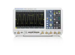
A touch above other oscilloscopes in
its segment, the R&S®MXO4 series
oscilloscope sports an impressive
13.3"Full HD capacitive touchscreen
and an intuitive user interface with a
learning curve of less than 15minutes.
The R&S®MXO4 series is the first of a new generation of oscilloscopes that excels in both performance and
value. The instruments deliver a once-in-a-decade engineering breakthrough for accelerated insight.
NEXT GENERATION TECHNOLOGY
R&S®MXO4 SERIES OSCILLOSCOPES
WHY ENGINEERS
CONTINUE TO UPGRADE
TO ROHDE & SCHWARZ
OSCILLOSCOPES?
►
Trusted, global high-quality company with long-term customer
commitment and technology innovation
►
Industry’s newest oscilloscope portfolio from 60MHz to 16GHz
►
ASIC investments enable world’s most responsive oscilloscopes
►
Frontend technology developments offer pristine signal integrity
►
16bit and 18bit architectures with HD mode provide highest
resolution
►
Digital triggering delivers world’s most sensitive event isolation
►
Superior user interface and front panel experience

Rohde & Schwarz R&S®MXO4 Series Oscilloscope 3
FEATURES AND
BENEFITS
CONFIGURATION
CONTENTS
APPLICATIONS
Enabling technology blocks
►
page 4
Find signal anomalies quickly
►
page 5
See your signals accurately
►
page 6
Capture more time
►
page 7
Isolate events with more precision
►
page 8
Spectrum analysis
►
page 9
Superior user experience
►
page 10
Enhanced usability
►
page 12
Fun to drive
►
page 14
Your go-to tool
►
page 15
EMI debugging
►
page 16
Logic analysis
►
page 17
Serial bus analysis
►
page 18
Power analysis
►
page 20
Frequency response analysis
►
page 21
Power integrity
►
page 22
Integrated arbitrary generator
►
page 23
Extensive probe portfolio
►
page 24
And there is so much more ...
►
page 27
► 200MHz to 1.5GHz bandwidth
► Up to 5Gsample/s sample rate
► 400Mpoints per channel standard
memory
► 12bit ADC at all sample rates
► 18bit architecture with HD mode
► Precise digital trigger

4
ENABLING TECHNOLOGY BLOCKS
The R&S®MXO4 series oscilloscopes utilize leading-edge technologies to achieve fast and accurate results.
Custom technology and innovative features in our oscilloscopes quickly boost your understanding of circuit
behaviors.
MXO-EP processing ASIC
See more of your signals, faster.
At the heart of each R&S®MXO4 series oscilloscope is a Rohde & Schwarz
developed application specific integrated circuit (ASIC): MXO-EP (extreme per-
formance). MXO-EP processes 200Gbit/s to deliver the world’s fastest update
rate of up to 4.5million acquisitions/s. See and capture more of your signal,
faster. Find rare signal anomalies quickly. Experience the most responsive oscil-
loscope in the industry.
Responsive deep memory
Capture more of your signals.
R&S®MXO4 series oscilloscopes come equipped with the industry’s deepest
standard acquisition memory of 400Mpoints per channel. Capture up to 80ms
of power up or power down sequences with the highest sample resolution of
200ps. The memory controller in the MXO-EP ASIC ensures the oscilloscope
stays responsive with deep memory.
12bit ADC, 18bit vertical architecture
Measure your signals accurately.
Measurement accuracy is highly dependent on the components in the sig-
nal path, e.g. amplifiers, samplers and A/D converters. The workhorse of the
R&S®MXO4 series is an extremely low noise signal path including a 12bit
ADC. High definition mode (HD) increases vertical resolution to industry best
18bit architecture. Get accurate measurements all the time.
THAT HELP GIVE YOU ACCELERATED INSIGHT
Advanced digital triggering system
Easily isolate subtle signal variations
MXO-EP ASICs incorporate advanced digital triggering that evaluates the A/D
converter samples in the acquisition path in real time. Trigger on small events
of less than 1/10 000 vertical division that no other oscilloscope can isolate.
Choose your own trigger hysteresis. Apply digital filters to suppress noise to
get the most precise triggering available.
50
0 1 2 43
Rohde & Schwarz R&S®MXO4 Series Oscilloscope 5
►
World’s fastest acquisition rate of up to >4.5million waveforms/s shows infrequent anomalies instantly
►
Up to 90 % real-time signal capture and display ensures instant display of all signal detail
►
MXO-EP based processing ASIC ensures responsive deep memory
World’s fastest update rate
The R&S®MXO4 oscilloscope processing path implements
a dedicated ASIC: the MXO-EP (extreme performance).
With optimized signal processing, the R&S®MXO4 oscillo-
scopes reach an exceptional update rate. The unique archi-
tecture allows the R&S®MXO4 to acquire, process and
display up to 4.5million waveforms/s.
FIND SIGNAL ANOMALIES QUICKLYENABLING TECHNOLOGY BLOCKS
WITH UNPARALLELED UPDATE RATES
Quickly and reliably detect sporadic signal faults
The statistical confidence in results is higher the more
waveforms are acquired. A high update rate increases the
likelihood of detecting and displaying signal faults and
including them in analysis. The high update rate enables
the R&S®MXO4 to generate trustworthy statistical results
based on a high number of waveforms in a short time. This
is crucial for quickly understanding electronic circuits.
Available with active automatic measurements, FFT or cursor
measurements
The R&S®MXO4 oscilloscopes have a high update rate
even when FFTs, automatic measurement or cursor mea-
surements are active. Also when performing analysis with
deep memory acquisitions, the ASIC based signal process-
ing paths ensure smooth workflows.
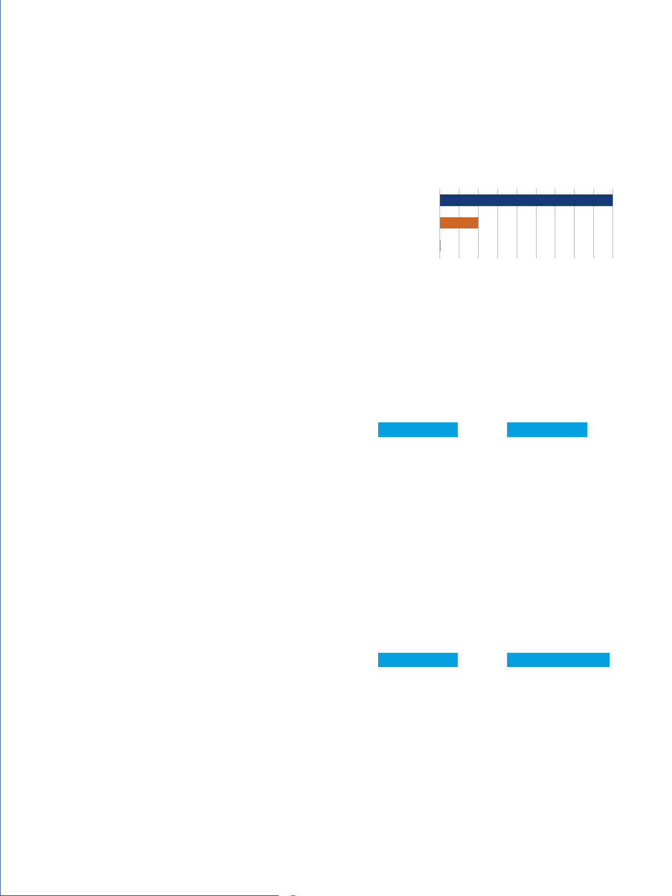
Real-time acquisition rate
Typical update rate 45 000 FFT/s
Typical update rate 4.5 million waveforms/s
R&S®MXO4
Competitor 1 (4000 class)
Competitor 2 (4000 class)
4.5
million
1 million
Rate in waveforms/s
0.5 1.5 2.5 4.53.5
6
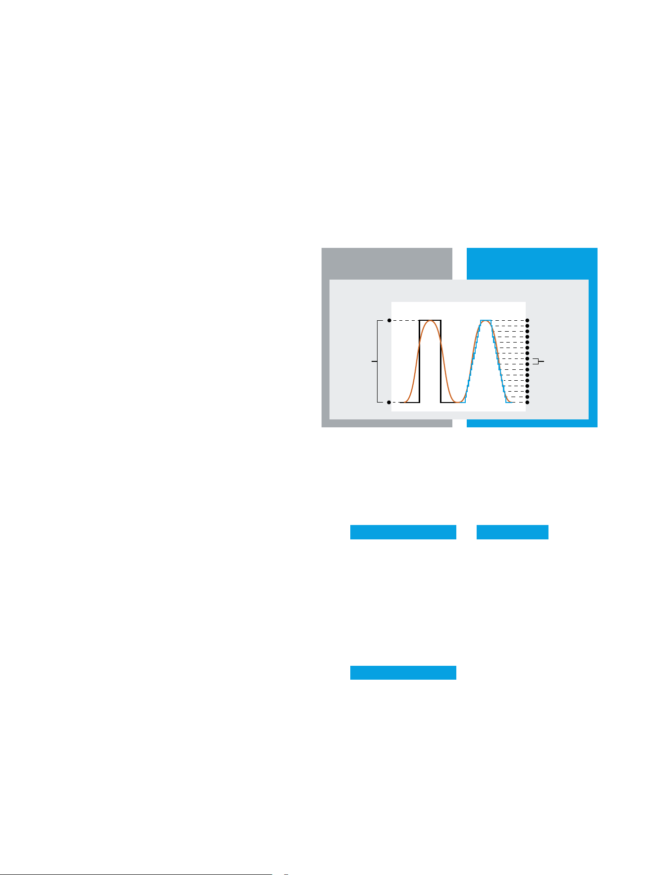
12bit ADC: all the time
All R&S®MXO4 series oscilloscopes incorporate a 12bit
A/D converter. 12bit vertical resolution delivers 4096
quantization levels for precise vertical sampling. This is a
16x improvement over 8bit ADCs. The ADC stays in 12bit
mode all the time, even at the fastest sample rates.
Vertical sensitivity to 500µV/div with ±5V offset range
The R&S®MXO4 series oscilloscope offers an outstand-
ing sensitivity down to 500µV/div without any unexpected
reduction in bandwidth. With offset of ±5V at higher sen-
sitivity vertical scale, you can easily place the signal at the
center of the screen. Extended offset enables use of more
sensitive vertical resolution, meaning higher ADC bits and
lower noise.
SEE YOUR SIGNALS ACCURATELY
LOWEST MEASUREMENT NOISE AND
HIGHEST VERTICAL RESOLUTION
18bit architecture with HD mode
Offering a user tradeoff between bandwidth and bits of
resolution, HD mode, implemented in hardware for fast
speed, achieves up to 18bit vertical resolution. This allows
you to see sharper waveforms with more signal details
that would otherwise be masked by noise. In addition to
superior vertical resolution, R&S®MXO4 oscilloscopes are
engineered with the lowest-in-industry system measure-
ment noise of just 22µV AC (RMS) at 1mV/div.
►
12bit ADC vertical resolution at all sample rates without tradeoffs
►
18bit architecture with HD mode
►
Low noise of 50Ω (1mV/div setting)
—
104mV (at 1GHz normal mode)
—
56µV (at 500MHz HD mode, 14bit)
►
Vertical scaling down to 500µV/div at full bandwidth
►
Industry’s highest available offset range of ±5V at 500µV/div
Traditional oscilloscope
8bit ADC
R&S®MXO4 series
12bit ADC
Finest resolution for a 1V (V
pp
) signal
4mV
8bit ADC 12bit ADC
0.244mV
Typical vertical resolution 18bit resolution
5V offset at 500µV/div
2
500 150100 250200 350300 450400
400
Rohde & Schwarz R&S®MXO4 Series Oscilloscope 7
Deep memory as an insurance policy
After bandwidth and sample rate, memory depth is the
most important attribute that determines the product’s
ability to handle a large range of troubleshooting tasks.
More acquisition memory gives oscilloscopes the ability
to capture more time. More memory enables the oscil-
loscope to retain rated sample rate and bandwidth with
slower timebase settings.
With 400Mpoints acquisition memory standard on all four
channels simultaneously, the R&S®MXO4 series oscillo-
scope offers up to 100 times the standard memory com-
pared to the primary competitor.
Standard segmented memory
Use segmented memory to capture signals separated
by inactivity. Examples include laser pulses, serial bus
activity and RF pulses. The segmented memory of the
R&S®MXO4 series oscilloscope enables signal capture
over a long observation period up to 1 000 000 segments.
CAPTURE MORE TIME
DEEPEST STANDARD MEMORY
Standard history capability
Press stop and use history mode to see previously cap-
tured acquisitions. History mode is an always-on capabil-
ity. All measurement and analysis tools are available in his-
tory mode including the serial bus decoder, mask test and
automatic measurements.
Maintain fast sampling rates with slow timebase settings
Ever adjust your oscilloscope timebase to capture more
time intervals, press stop, then zoom in to find signal
details that do not look right? If so, you have experienced
the aliasing problem that oscilloscopes with shallow mem-
ory have. The deep memory of the R&S®MXO4 enables
longer time captures at full sample rate.
►
Industry’s deepest memory of 400Mpoints per channel (optional 800Mpoints interleaved)
►
Standard segmented memory (10 000 segments, optional 1 000 000 segments)
►
Standard history mode (10 000 acquisitions, optional 1 000 000 acquisitions )
Need even more memory?
During tests that involve looking at power up/down behav-
ior or decoding longer bus events, there is always the wish
to record longer time intervals. The memory extension
option turns on 800Mpoints (interleaved 2 channels), up
to 1 000 000 segments and up to 1 000 000 acquisitions.
Standard memory per channel
Total capture of 400 ms
1 Mpoint memory 800 Mpoint memory
Traditional single-shot acquisition
Total acquisition time = memory depth/sample rate
Segmented memory acquisition
Segmented acquisition time = memory depth/# of segments
Segment#1 #2 #3 #4 #5
R&S®MXO4
Competitor 1 (4000 class)
Competitor 2 (4000 class)
31.25
Memory in Mpoints

8
Modern digital trigger
The MXO-EP ASIC incorporates the Rohde & Schwarz pat-
ented digital trigger system. Digital triggering implies a
common path for the measurement signal and trigger ver-
sus a split path in older analog trigger architectures. Digital
triggers offer numerous advantages.
User selectable hysteresis
Use automated trigger hysteresis settings or manually
enter your values. Unlike using oscilloscopes with analog
triggers, R&S®MXO4 series users have full access to con-
trol all trigger hysteresis settings. This provides additional
flexibility for determining where to trigger, including how
much trigger noise suppression is desired.
ISOLATE EVENTS WITH MORE
PRECISION
HIGH-PRECISION DIGITAL TRIGGER
World’s most sensitive trigger
The R&S®MXO4 series digital trigger is up to 10 000 times
more sensitive than all competitors that are still using older
analog trigger architectures. Triggering sensitivity enables
users to isolate difficult-to-find small physical layer anoma-
lies in the presence of large signals, accelerating debug
and troubleshooting.
Adjustable digital trigger filters
Use the up to 18bit HD mode on the trigger to reduce
measurement system noise. The digital trigger architec-
ture makes it possible to adapt the cutoff frequency of the
digital lowpass filter to the signal to be measured. Unlike
oscilloscopes with analog trigger circuits, the same filter
settings can be used for both the trigger signal and the
measurement signal. As a result, noise on the trigger sig-
nal can be suppressed, for instance while simultaneously
capturing and displaying the filtered or unfiltered measure-
ment signal.
►
Industry's most sensitive trigger: 1/10 000 vertical division
►
Best in class trigger jitter of just 1ps
►
World’s fastest trigger rearm time of <21ns
►
Adjustable digital trigger lters
►
User-selectable hysteresis
............ Trigger threshold ............
Hysteresis
High
Low
1 div
Trigger on signals
only 0.01div high

Rohde & Schwarz R&S®MXO4 Series Oscilloscope 9
SUPERIOR RF MEASUREMENT CAPABILITY
►
Pristine RF spectrum
►
Dedicated RF controls
►
RF/time domain views with independent controls
►
Gated spectrum for easy correlation between frequency and time
SPECTRUM ANALYSIS
Automatic peak list and max./min. hold measurements
Rohde & Schwarz understands the need for an addi-
tional tool in spectrum measurements. This is why the
R&S®MXO4 includes advanced spectrum analysis func-
tions like max. and min. hold as well as peak list indication
as part of the standard features. This makes it easier to
navigate the plot and gain quick insights into the spectrum
diagram.
RF insights into your measurements
The R&S®MXO4 series oscilloscope is engineered with
spectrum analysis in mind to bring forward fast and pow-
erful analysis capabilities. It boasts an industry leading
spectrum acquisition rate of 45 000 FFT/s. This allows cap-
ture of spurious spectrum events, especially when doing
EMI debugging. The pristine RF characteristics of the
instrument balance great spectrum performance with the
synchronized time domain view.
Frequency analysis setup made easy
You can configure the spectrum analysis function of the
R&S®MXO4 by simply entering typical parameters: cen-
ter frequency, span and resolution bandwidth (RBW).
The spectrum settings are independent of the time
domain settings but the time and frequency domains are
time-correlated.
RF characteristics
Spectrum update rate >45 000 FFT/s
Sensitivity/noise density –160dBm (1Hz)
Noise figure 14dB
Dynamic range 106dB
SFDR 65dBc
Second harmonic distortion –60dBc
Third harmonic distortion –59dBc

3
5
6
7
4
2
1
10
Quick access to important tools
The toolbar
1
enables quick access to important tools.
Choose from a variety of tools and arrange them with
maximum flexibility. The main menu
2
provides access to
all instrument settings. Signal activators
3
on the left of
the main menu enable signal activation and quick access
to analog channel, math functions, FFT, signal generator
and serial protocols setup.
Search capability
Easily find any oscilloscope capability you are looking for
by simply typing it in the search menu
7
.
SUPERIOR USER EXPERIENCE
ADVANCED USABILITY, EASY DOCUMENTATION,
FAST REMOTE CONTROL
R&S®SmartGrid
Get an individual waveform layout on the screen using
R&S®SmartGrid
.
4
. See the fundamental signal param-
eters in the signal toolbar
5
. From here, drag & drop into
R&S®SmartGrid to change the waveform layout.
Enhanced touchability
The box design
6
implemented on all the instrument set-
tings provides enhanced touchability. Press on any part of
the box to change the value of the parameter.

Rohde & Schwarz R&S®MXO4 Series Oscilloscope 11
Save results fast
Save waveforms in various file formats or download them
via Ethernet or USB for later analysis with MATLAB® or
Excel. You can also save screen content, measurement
data and reports.
Documentation at the press of a button
Document your measurements quickly:
►
Screenshots include waveforms and results
►
Clear grid annotations for easy-to-read signal
characteristics
►
Color-coded labels highlight anomalies in the diagram
►
Save waveforms and measurement results in binary or
CSV formats for signal analysis on a PC
Remote control access: anytime, anywhere
Remotely control the oscilloscope and view the display on
a PC or mobile device. View the same user interface on
the oscilloscope. All oscilloscope functions are also avail-
able remotely via Ethernet or the USB interface.
Language selection
The R&S®MXO4 series user interface supports multiple
languages. Just a few seconds are needed to switch lan-
guages while the instrument is running, making the oscil-
loscope truly international.
Miscellaneous
Contents
waveform complete
selection (zoom, cursor, gate, manual)
number of acquisitions
history memory
measurement results
Format
measurement
data
binary, CSV, 1 to 4 channels
graphics PNG, JPG, BMP, TIF, PDF
Drivers
VXI, LabView, LabWindows, .NET
Remote control
web interface, VNC, SCPI
Languages
choose from 13

12
13.3" high resolution, multitouch display
►
High resolution: 1920×1080 pixel (Full HD)
►
Gesture support speeds up scaling and zooming
►
Easy to see signal detail
ENHANCED USABILITY
Integrated arbitrary waveform generator
►
Two-channel 100MHz waveform generator
►
Wide range of waveform and modulation types
►
Easy setup of frequency, amplitude, offset and noise
16 logic channels
►
Add 16 logic channels without reduction of analog channels
►
High MSO sample rates ensure timing accuracy
Interfaces
►
Three USB 3.0 and two USB 2.0 ports
►
USB device port, Ethernet
►
HDMI™ port

Rohde & Schwarz R&S®MXO4 Series Oscilloscope 13
16 logic channels
►
Add 16 logic channels without reduction of analog channels
►
High MSO sample rates ensure timing accuracy
Intuitive front panel increases productivity
►
Fast, direct access to primary instrument settings
►
Quickly adjust settings with knobs and buttons
►
Sectional layout makes nding the right button easy
Active probe interface
►
Supports over 30 Rohde & Schwarz current and voltage
probes
►
50Ω and 1MΩ path enable support of an even wider
range of passive and active probes, including ones from
third parties
Clear orientation with color-coded LEDs
►
Color-coded buttons and knobs enable fast association
with sources
►
Indication of currently selected channel
►
Selection between ne/course adjustments made simple

14
Superior usability
Extensive user feedback and research into the smart
device user interface concept led to the development of
the R&S®MXO4 series user interface:
►
Navigate anywhere from the pull-up menu in the lower
right corner. Positioned close to the front panel, this
leads to reduced hand movement when switching
between the two menu dialogs
►
Left-hand tab dialogs produce small areas, maximizing
waveform viewing
►
Box design to touch anywhere in a large target area
►
Signal icons make it easy to turn on/off sources and to
adjust the R&S®SmartGrid layout
►
Unique in the industry, use the tool bar to quickly
access your favorite tools
►
Use the re-purposed toolbar space to modify existing
elements such as cursors, measurements and spectrum
settings, or to quickly delete elements
►
Fast one-touch access to the trigger setup, horizontal
settings and acquisition control directly from the
information panel
►
Select the Rohde & Schwarz icon to see current
instrument details including LAN IP and rmware
version
►
UI consistency with the R&S®RTO6 and R&S®RTP
oscilloscopes
FUN TO DRIVE
15-MINUTE LEARNING CURVE, SUPERIOR TOUCH,
INTUITIVENAVIGATION
Left hand
tab dialog
Box
design
Configurable toolbar

Rohde & Schwarz R&S®MXO4 Series Oscilloscope 15
READY FOR MANY USES
YOUR GO-TO TOOL
Need additional logic channels?
Add 16 digital channels with the R&S®MXO4-B1 MSO
option. Unlike some other oscilloscopes that force a
tradeoff between digital and analog channel usage, the
R&S®MXO4 series logic channels can be used simul-
taneously with all analog channels. Simply connect an
R&S®MXO4-B1 probe to the R&S®MXO4 to use the digital
channels.
An oscilloscope as flexible as you
Need additional test capability? Customize your
R&S®MXO4 series oscilloscope with the application soft-
ware and probes that your applications need.
Need configurable waveform generation?
With the R&S®MXO4-B6 waveform generation option, you
can add two integrated 100MHz arbitrary waveform gen-
erators. Captured waveforms on the oscilloscope can be
replayed by the generator and noise can be added to cre-
ate worst case performance to determine system toler-
ance. Select from a wide range of available waveshapes or
load an arbitrary waveform.
Choose from a wide selection of compatible probes
Rohde & Schwarz provides a broad portfolio of current and
voltage probes. All R&S®MXO4 series oscilloscope chan-
nel inputs include a Rohde & Schwarz probe interface con-
nection for Rohde & Schwarz active probes. Moreover,
many third-party probes are also compatible with the
instrument.

16
Easy navigation in frequency domain
The R&S®MXO4 spectrum function has the familiar inter-
face of a spectrum analyzer. The spectrum setup dialog
offers basic spectrum analyzer controls such as start and
stop frequency and resolution bandwidth. In spectrum
mode, the R&S®MXO4 time domain settings are unaf-
fected. This makes navigation in the frequency domain
an easy task. The maximum FFT capture bandwidth cor-
responds to the R&S®MXO4 series bandwidth allowing a
quick overview of all the test device’s emissions from 0Hz
to 1.5GHz.
EMI DEBUGGING
The right setup with the right probes
Rohde & Schwarz offers the compact R&S®HZ-15 near-field
probe set, which is particularly helpful for EMI debugging
of embedded designs. The most compact probe in this set
allows capturing of near-field emissions from single circuit
lines. The R&S®HZ-15 covers the frequency range from
30MHz to 3GHz. With reduced sensitivity, it can also be
used below 30MHz. The optional R&S®HZ-16 preamplifier
provides 20dB gain in the frequency range from 100kHz
to 3GHz, in case higher sensitivity is needed.
Ultra-fast spectrum acquisitions for spurious spectrum events
The R&S®MXO4 series architecture is optimized both in
hardware and software to leverage the powerful ASIC
capabilities to deliver fast and responsive spectrum cap-
tures. This is critical in detecting random and spurious
emissions that are otherwise hidden due to the blind time
in acquisitions. The spectrum analysis is equipped with
max. hold, min. hold and average arithmetics to keep track
of spectrum events that occur during the testing. These
are important test receiver functions and now they come
standard on the R&S®MXO4 series spectrum function.
Gated spectrum for correlated time and frequency analysis
With the gated spectrum function, it is possible to restrict the spectrum analysis to a user-defined region of the captured
time domain signal. Excessive spectral emissions can be correlated to dedicated time periods in a signal. Typical appli-
cations include the correlation of unwanted emissions to fast switching edges in switched-mode power supplies or to
data transfers on bus interfaces. Having identified the problem, the design engineer can easily check the effectiveness
of different solutions such as blocking capacitors or reduced rise/fall times by observing the level change of the spectral
emission.

Rohde & Schwarz R&S®MXO4 Series Oscilloscope 17
Logic analysis enabled by default
All R&S®MXO4 series oscilloscopes have the
R&S®MXO4-B1 MSO hardware built into every instrument.
The MSO option offers the logic probes required to start
using the 16 digital channels.
LOGIC ANALYSIS
See more signal details with fast sample rate and deep
memory
With a sampling rate of 5Gsample/s, the R&S®MXO4
series oscilloscope provides high time resolution of 200ps
for all digital channels. This sampling rate is available over
the entire memory depth of 400Mpoints per channel. The
MSO option offers comprehensive trigger capabilities to
detect critical events such as narrow glitches or certain
pattern combinations.
Analysis of low speed serial buses with digital channels
Today, high speed interfaces are often combined with low speed control or programming buses in a single device. You
can use the digital channels of the R&S®MXO4-B1 option to trigger and decode low speed serial protocols such as SPI
and I
2
C with the appropriate protocol options. All protocol analysis tools for the analog channels, such as decode table
and search, are also available for the digital channels. Trigger on protocol details such as start, address and data in order
to focus the analysis on dedicated events.

18
Dual-path protocol analysis
With the R&S®MXO4 series, you can experience protocol analysis innovation. Typically, protocol packets must be
acquired at the same sample rate as the rest of the oscilloscope.
With dual-path protocol analysis, you can set the instrument sample rate for the waveform path and the oscilloscope will
automatically use another internal decoupled sample rate for the decoding path. Even with very slow sample rates, the
protocol data is correctly decoded. On other oscilloscopes, signals would be undersampled and decoding would not be
possible.
SERIAL BUS ANALYSIS
Trigger and decode packages
Option Description Buses
R&S®MXO4-K510
1)
low speed serial buses I²C/SPI/RS-232/RS-422/RS-485/UART
R&S®MXO4-K520
1)
automotive buses CAN/LIN/CAN-FD/CAN-XL
1)
Available with future firmware release.
Capture more packets with deep memory
Need to capture long time periods? You can use deep
memory to capture more packets. With a memory depth
of up to 800Mpoints, the R&S®MXO4 series can cap-
ture long time periods where the cause and result are
distanced in time. Over the entire capture, signal detail is
time-correlated with packet content for fast debug.
Undersampled data; unreliable decoding Undersampled data; perfectly decoded frames

Rohde & Schwarz R&S®MXO4 Series Oscilloscope 19
Individual screen setup
The decoded layer condenses or expands using the vertical and horizontal control knobs or using fingers on the touch-
screen. Use the R&S®SmartGrid function to rearrange the windows displayed on the screen to best fit your viewing pref-
erences. The decoded bus can be overlaid on the captured signal and/or displayed in a separate window.
200 6040 10080 140120 180160
160
20
See power signal details with up to 18 bit resolution
Even the smallest signal details of a highly dynamic signal
matter for power measurements, for example when verify-
ing RDS
on
for a MOSFET. The HD mode of the R&S®MXO4
series oscilloscope increases the vertical resolution up to
18 bit so that previously unseen signal details become vis-
ible and can be measured. The oscilloscope also offers
adjustable digital filters that allow noise suppression result-
ing in sharper waveforms with more signal details.
POWER ANALYSIS
Extensive probe portfolio: High voltage and current probes
The Rohde & Schwarz portfolio of high voltage probes
includes active differential probes for voltages up to
6000V (peak). These probes provide an exceptional com-
mon mode rejection ratio over a broad frequency range.
Rohde & Schwarz current probes enable accurate, non-
intrusive measurement of DC and AC currents. Different
models are available to measure currents in the range
from 1mA to 2000A with a maximum bandwidth of up to
120MHz.
Digital trigger for enhanced debugging capabilities
With up to 18bit vertical resolution, the digital trig-
ger architecture enables triggering on the smallest ver-
tical variation sampled. The trigger sensitivity requires
0.0001div and is adjustable to factor in different trig-
ger requirements, for example to avoid false trigger-
ing on noise. It is also possible to use the digital trigger
to adapt the cutoff frequency only on the trigger path
while maintaining the original waveform for viewing and
measurements.
Maintaining fast sample rates with deepest memory
Analyzing start-up, shut-down or transients of power sup-
plies requires a high sample rate and long recording times.
With up to 800Mpoints memory, highest in its class, the
R&S®MXO4 series oscilloscopes enable recording of long
duration while maintaining high sample rates of up to
5Gsample/s.
Triggering not possible Digital trigger and HD mode
Acquisition time (at 5Gsample/s)
R&S®MXO4
Competitor 1 (4000 class)
Competitor 2 (4000 class)
12.5
Time in ms
0.8

Rohde & Schwarz R&S®MXO4 Series Oscilloscope 21
Perform low-frequency response analysis
The R&S®MXO4-K36 frequency response analysis (FRA)
option lets you perform low-frequency response analy-
sis on your oscilloscope easily and quickly. It character-
izes the frequency response of a variety of electronic
devices, including passive filters and amplifier circuits.
For switched-mode power supplies, it measures the con-
trol loop response (CLR) and power supply rejection ratio
(PSRR).
The FRA option uses the oscilloscope’s built-in waveform
generator to create stimulus signals ranging from 10Hz to
100MHz. Measuring the ratio of the stimulus signal and
the output signal of the DUT at each test frequency, the
oscilloscope plots gain and phase logarithmically.
FREQUENCY RESPONSE ANALYSIS
Features and functionalities
Amplitude profile
The R&S®MXO4-K36 provides user-configurable profiles of
the amplitude output level from the generator. This helps
improve signal-to-noise ratio (SNR) at different frequency
ranges when performing measurement on CLR and PSRR.
Users can also load lookup tables for generator settings.
Improved resolution and marker support
This includes user configurable points per decade to adjust
needed resolution and sweep time. Markers are available
on the traces with a table to show corresponding coordi-
nates. Users can easily determine the phase and gain mar-
gin with an auto placement function.
Parallel display of time domain
Having both time and frequency domain views allows the
user to monitor if the injected signal causes distortion that
leads to errors in the measurement. These effects are hard
to spot from just the Bode plot. Using the time domain
window of the oscilloscope is a great way to adjust the
amplitude profile to the optimal level.
Measurement table
The table of measurement results provides information
about each measured point, consisting of frequency, gain
and phase shift. The markers and table allow interactive
display of the selected information. For reporting pur-
poses, screenshots, table results or both can be quickly
saved to a USB device.
Broad probe portfolio
Accurate CLR and PSRR characterization is highly depen-
dent on choosing the right probes since the peak-to-peak
amplitudes of both V
in
and V
out
can be very low at some
test frequencies. These values could be buried in the oscil-
loscope’s noise floor and in the switching noise of the DUT
itself. We recommend the low-noise R&S®RT-ZP1X 38MHz
bandwidth 1:1 passive probes to reduce attenuation error
and provide the best SNR.
Making bode plots with R&S®MXO4 series

22
Accurately measure ripple and PARD
As power rail tolerance levels get smaller, it becomes
increasingly difficult to measure power ripple accurately.
The inherent low noise of the R&S®MXO4 series enables
accurate power integrity measurements on the millivolt
level. The fast update rate of the R&S®MXO4 series allows
you to quickly see infrequent and worst-case ripple as well
as periodic and random disturbance (PARD) anomalies.
Debugging and validating power rails
POWER INTEGRITY
Measuring small voltages riding on large DC offsets
With the ±60V offset compensation range, the
R&S®RT-ZPR power rail probes allow you to focus on small
ripples on the power rail’s DC voltage. Whether you need
to zoom in on a 1V or much higher DC level, the probe
provides the required offset while maintaining lowest ver-
tical scale settings. Together with the superb low noise
frontend of the R&S®MXO4 series oscilloscope and the
18bit vertical resolution, this combination provides accel-
erated insight into the power integrity of your design.
Power rail characterization with high fidelity probes
Wide bandwidth, high sensitivity, very low noise and extra-
large offset compensation make the R&S®RT-ZPR an excel-
lent probe for characterizing power rails. With a bandwidth
of up to 4GHz, excellent sensitivity due to the 1:1 attenu-
ation ratio and low noise, the R&S®RT-ZPR excels at pre-
cise ripple measurements. Coupled with the oscilloscope’s
powerful frequency analysis capabilities, the R&S®RT-ZPR
probes can be used to isolate periodic and random distur-
bances (PARD). An integrated high-precision, 18bit DC
voltmeter provides an instantaneous DC voltage readout in
parallel.
Find coupled sources with fast spectrum
With the industry’s most capable spectrum, you can see switching characteristics or quickly scan for sources coupled
onto the power rail. The R&S®MXO4 series oscilloscope spectrum algorithm allows you to analyze the spectrum inde-
pendently of the time domain settings. This quickly provides a comprehensive picture of your power rails.
Using spectrum analysis with time gating to effectively find coupled sources that contribute to power rail noise

Rohde & Schwarz R&S®MXO4 Series Oscilloscope 23
Two-channel 100MHz arbitrary waveform generator
Equipped with the R&S®MXO4-B6 option, the R&S®MXO4
series oscilloscope offers a fully integrated two-chan-
nel 100MHz arbitrary waveform generator. With
625Msample/s and 16bit resolution, the generator is suit-
able for implementing prototype hardware and for educa-
tional purposes. The integrated generator provides both
standard and arbitrary stimulus to the DUT. The generator
can be operated as a function or modulation generator. It
also supports sweep mode.
INTEGRATED ARBITRARY GENERATOR
Compact and configurable
Wide range of waveforms and modulation types
The integrated arbitrary waveform generator provides
stimulus output of sine, square, pulse, ramp, triangle, sinc,
arbitrary and noise waveforms to your device under test.
For all waveforms, you can set the frequency, amplitude,
offset and noise and also add a burst.
The modulation feature supports AM, FM, FSK and PWM
modulations with modulation shapes of sine, rectangle, tri-
angle and ramp.
Waveform generator specifications
Analog output 2 channels
Bandwidth 100MHz
Amplitude
high-Z: 10mV to 10V (peak-to-peak),
50Ω: 5mV to 5V (peak-to-peak)
Arbitrary waveform sample rate 1sample to 40Msample on each channel
Sample rate 1sample/s to 312.5Msample/s
Resolution 16bit
Operating modes
►
function and arbitrary waveform generator (DC, sine, square, pulse, triangle, ramp,
inverse ramp, sinc, arbitrary)
►
modulation (AM, FM, FSK, PWM)
►
frequency sweep
►
noise

24
Extensive probe range for all measurement tasks
A complete portfolio of high-quality passive and active
probes covers all measurement tasks. With an input
impedance of 1MΩ, the active probes only put a mini-
mum load on the signal source operating point. The very
large dynamic range, even at high frequencies, prevents
signal distortion, e.g. 60V(V
pp
) at 1GHz for the active sin-
gle-ended probes.
Complete portfolio for power measurements
The portfolio of dedicated probes for power measure-
ments includes active and passive probes for the different
voltage and current ranges – from μA to kA and from μV
to kV. Dedicated power rail probes detect even small and
sporadic distortions on DC power rails.
EXTENSIVE PROBE PORTFOLIO
THE RIGHT PROBE FOR THE BEST MEASUREMENT

Rohde & Schwarz R&S®MXO4 Series Oscilloscope 25
Micro button for convenient instrument control
The situation is familiar to all engineers: You have carefully positioned
the probe on the DUT and you want to start the measurements, but
you don't have a free hand. The micro button on Rohde & Schwarz
active probes solves the problem. It is conveniently situated on the
probe tip, and you can assign it different functions such as run/stop,
autoset and adjust offset.
High-voltage differential probes
The R&S®RT-ZHD series high voltage differential probes provide
excellent common mode rejection ratio (CMRR) over a broad fre-
quency range with a 200MHz bandwidth and can safely measure up
to 6000V peak voltages. These probes have exceptionally low noise,
making them ideal for switching power analysis.
Like the rest of the Rohde & Schwarz probe family, the R&S®RT-ZHD
probes are also equipped with the high precision R&S®ProbeMeter,
offering 0.1 % accuracy while ensuring 0.5 % gain accuracy and very
low drift in measurements. They also have an integrated 5MHz ana-
log filter and audible overrange indicator and micro buttons to give
users full awareness of and control over the probe measurements.
Micro button
High voltage differential probes for switching power analysis measurements

26
Rohde & Schwarz has a comprehensive probe portfolio to meet every probing need.
► For more information, see "Probes and accessories for Rohde & Schwarz oscilloscopes"
(PD 3606.8866.12).
Standard passive probes
(38MHz to 700MHz)
R&S®RT-ZP11, R&S®RT-ZP1x
Passive probes are standard accessories for
Rohde & Schwarz oscilloscopes. They are low-cost,
general purpose probing solutions for a broad range
of applications.
Passive broadband probes
(8GHz)
R&S®RT-ZZ80
These are an economical yet powerful alternative
to active probes for measuring high speed signals
on low impedance lines. Their input impedance is
low and remains practically constant over the entire
frequency range. They feature extremely low input
capacitance, very low noise and high linearity.
Active single-ended broadband probes
(1GHz to 6GHz)
R&S®RT-ZS10L, R&S®RT-ZS10E, R&S®RT-ZS10,
R&S®RT-ZS20, R&S®RT-ZS30, R&S®RT-ZS60
Very wide dynamic range, exceptionally low off-
set and gain errors combined with the right acces-
sories make these probes the ideal accessory for
Rohde & Schwarz oscilloscopes.
EMC near-field probes
(30MHz to 3GHz)
R&S®HZ-15, R&S®HZ-17
Powerful E and H near-field probes for the fre-
quency range from 30MHz to 3GHz with an
optional preamplifier expand the application range
of the R&S®MXO4 series oscilloscope to include
EMI debugging.
Current probes
(20kHz to 120MHz; ±1 mA to 2000 A)
R&S®RT-ZC02, R&S®RT-ZC03, R&S®RT-ZC05B,
R&S®RT-ZC10, R&S®RT-ZC10B, R&S®RT-ZC15B,
R&S®RT-ZC20, R&S®RT-ZC20B, R&S®RT-ZC030,
R&S®RT-ZC31
Rohde & Schwarz current probes enable accurate,
non-intrusive measurement of DC and AC currents.
Different models are available to measure currents
in the range from 1mA to 2000 A with a maximum
bandwidth of up to 120MHz. Current probes are
available with the Rohde & Schwarz probe interface
or BNC with external power supply.
High voltage probes
(100MHz to 400MHz; ±750V to ±6000V)
R&S®RT-ZH03, R&S®RT-ZH10, R&S®RT-ZH11,
R&S®RT-ZD01, R&S®RT-ZHD07, R&S®RT-ZHD15,
R&S®RT-ZHD16, R&S®RT-ZHD60
The Rohde & Schwarz portfolio of high voltage
probes includes passive single-ended and active
differential probes for voltages up to 6000V (peak).
Different models allow measurements in up to
CATIV environments. Differential probes provide
an exceptional common mode rejection ratio over a
broad frequency range.
Power rail probes
(2GHz and 4GHz)
R&S®RT-ZPR20, R&S®RT-ZPR40
Wide bandwidth, high sensitivity, very low noise
and extra-large offset compensation make the
R&S®RT-ZPR power rail probes an excellent tool for
characterizing power rails. An integrated high accu-
racy DC voltmeter provides instantaneous DC volt-
age readout.
Active differential broadband probes
(1GHz to 4.5GHz)
R&S®RT-ZD10, R&S®RT-ZD20, R&S®RT-ZD30,
R&S®RT-ZD40
The flat frequency response and high input imped-
ance with low input capacitance permit precise
measurements on differential signals while keeping
the DUT load low. The high common mode rejec-
tion over the entire probe bandwidth ensures high
immunity to interference. Special browser adapters
allow flexible contacting with high signal fidelity.
R&S®RT-ZA15 external
attenuator for
R&S®RT-ZD20/-ZD30
R&S®RT-ZD40: browser adapters
to easily vary the pin offset

Rohde & Schwarz R&S®MXO4 Series Oscilloscope 27
Grows with your needs – fully software based upgrades
The R&S®MXO4 series flexibly adapts to relevant project updates. You can simply install the necessary software
licenses, e.g. triggering and decoding of serial protocols or the frequency response analysis option. The waveform gen-
erator and MSO capabilities are built-in and just need to be activated. The bandwidth can be upgraded up to 1.5GHz via
keycode. All this makes retrofitting very easy.
Regular firmware improvements
Regular firmware updates consistently add new functions to the R&S®MXO4 series oscilloscopes. Download the lat-
est firmware version at www.rohde-schwarz.com and use a USB storage device or LAN connection for installation. Your
R&S®MXO4 series oscilloscope is always up-to-date.
Multilingual support: choose among thirteen languages
The user interface and online help of the R&S®MXO4 series oscilloscope support thirteen languages (English, German,
French, Spanish, Italian, Portuguese, Czech, Polish, Russian, Simplified and Traditional Chinese, Korean and Japanese).
You can change the language in just a few seconds while the instrument is running.
Safe transport and easy rack mounting
An extensive selection of storage and transportation accessories means the R&S®MXO4 series oscilloscopes are
always fully protected and easy to transport. The rackmount kit allows easy installation of the oscilloscope in integrated
environments.
AND THERE IS SO MUCH MORE ...
AN OSCILLOSCOPE THAT EVOLVES WITH YOUR NEEDS
Accessories
Front cover R&S®MXO4-Z1
Soft carrying case R&S®MXO4-Z3
Transit case, with trolley function R&S®MXO4-Z4
19" rackmount kit R&S®ZZA-MXO4
VESA mount
standard 100mm × 100mm VESA pattern on
back of all instruments

28
STILL UNDER REVISION
OSCILLOSCOPE PORTFOLIO
R&S® RTH1000 RTC1000 RTB2000 RTM3000 MXO4 RTE1000 RTO6 RTP
Vertical
Bandwidth 60/100/200/350/500MHz
1)
50/70/100/200/300MHz
1)
70/100/200/300MHz
1)
100/200/350/500MHz/1GHz
1)
200/350/500 MHz/1/1.5GHz
1)
200/350/500MHz/1/1.5/2GHz
1)
600MHz/1/2/3/4/6GHz
1)
4/6/8/13/16GHz
1)
Number of channels 2 plus DMM/4 2 2/4 2/4 4 2/4 4 4
ADC resolution; system
architecture
10bit; 16bit 8bit; 16bit 10bit; 16bit 10bit; 16bit 12bit; 18bit 8bit; 16bit 8bit; 16bit 8bit; 16bit
V/div, 1MΩ 2mV to 100V 1mV to 10V 1mV to 5V 500µV to 10V 500µV to 10V 500µV to 10V 1mV to 10V (with HD mode: 500μV to 10V)
V/div, 50Ω – 500µV to 1V 500µV to 1V 500µV to 1V 1mV to 1V (with HD mode: 500μV to 1V) 2mV to 1V (with HD mode: 1mV to 1V)
Horizontal
Sampling rate per channel
(in Gsample/s)
1.25(4 CH model);
2.5(2 CH model);
5(all channels interleaved)
1; 2 (2 CH interleaved) 1.25; 2.5(2 CH interleaved) 2.5; 5(2 CH interleaved) 2.5; 5(2 CH interleaved) 5 10; 20 (2 CH interleaved in 4GHz and 6GHz model) 20; 40 (2 CH interleaved)
Maximum memory
(per channel/1 channel active)
125kpoints (4 CH model);
250kpoints (2 CH model);
500kpoints
1Mpoints; 2Mpoints 10Mpoints; 20Mpoints 40Mpoints; 80Mpoints
standard: 400Mpoints;
max. upgrade: 800Mpoints
2)
50Mpoints; 200Mpoints
standard: 200Mpoints/800Mpoints;
max. upgrade: 1Gpoints/2Gpoints
standard: 100Mpoints/400Mpoints;
max. upgrade: 3Gpoints
Segmented memory standard, 50 Mpoints – option, 320 Mpoints option, 400 Mpoints
standard: 10 kpoints;
option: 1 Mpoints
standard standard standard
Acquisition rate
(in waveforms/s)
50 000 10 000
50 000 (300 000 in fast seg-
mented memory mode
2)
)
64 000 (2 000 000 in fast seg-
mented memory mode
2)
)
> 4 500 000 1 000 000 (1 600 000 in ultra- segmented memory mode) 1 000 000 (2 500 000 in ultra-segmented memory mode) 750 000 (3 200 000 in ultra-segmented memory mode)
Trigger
Types digital analog analog analog digital digital digital (includes zone trigger)
advanced (includes zone trigger
)
, digital trigger (14 trig-
ger types) with real-time deembedding
2)
, high speed
serial pattern trigger incl. 8/16 Gbps CDR
2)
Sensitivity – – at 1mV/div: >2 div at 1mV/div: >2 div
0.0001 division, all bandwidth,
user controllable
0.0001 division, all bandwidth, user controllable 0.0001 division, all bandwidth, user controllable 0.0001 division, all bandwidth, user controllable
Mixed signal option
Number of digital channels
1)
8 8 16 16 16 16 16 16
Analysis
Mask test tolerance mask tolerance mask tolerance mask tolerance mask
3)
user-configurable, hardware based user-configurable, hardware based user-configurable, hardware based
Mathematics elementary elementary basic (math on math) basic (math on math) basic (math on math) advanced (formula editor) advanced (formula editor, Python interface) advanced (formula editor, Python interface)
Serial protocols triggering and
decoding
1)
I
2
C, SPI, UART/RS-232/
RS-422/ RS-485, CAN, LIN,
CAN-FD, SENT
I
2
C, SPI, UART/RS-232/
RS-422/RS-485, CAN, LIN
I
2
C, SPI, UART/RS-232/
RS-422/RS-485, CAN, LIN
I
2
C, SPI, UART/RS-232/RS-422/
RS-485, CAN, LIN, I
2
S,
MIL-STD-1553, ARINC 429
I
2
C, SPI, UART/RS-232/RS-422/
RS-485, CAN
3)
, CAN-FD
3)
,
CAN-XL
3)
, LIN
3)
,
MIL-STD-1553
3)
, ARINC 429
3)
I
2
C, SPI, UART/RS-232/RS-422/RS-485, CAN, LIN, I
2
S,
MIL-STD-1553, ARINC 429, FlexRay™, CAN-FD,
USB 2.0/HSIC, Ethernet, Manchester, NRZ, SENT,
SpaceWire, CXPI, USB Power Delivery, automotive
Ethernet 100BASE-T1
I
2
C, SPI, UART/RS-232/RS-422/RS-485, CAN, LIN,
I
2
S, MIL-STD-1553, ARINC 429, FlexRay™, CAN-FD,
MIPI RFFE, USB2.0/HSIC, MDIO, 8b10b, Ethernet,
Manchester, NRZ, SENT, MIPI D-PHY, SpaceWire,
MIPI M-PHY/ UniPro, CXPI, USB3.1 Gen1, USB-SSIC,
PCIe 1.1/2.0, USB Power Delivery, automotive Ethernet
100BASE-T1/1000BASE-T1
I
2
C, SPI, UART/RS-232/422/485, SENT, LIN, CAN/-FD,
MIL-STD-1553, ARINC 429, SpaceWire, USB2.0/HSIC/PD,
USB3.1 Gen1/2/SSIC, PCIe 1.1/2.0/3.0, 8b10b,
MIPI RFFE, MIPI D/M-PHY/UniPro, Auto Ethernet
10/100/1000BASE-T1, Ethernet 10/100BASE-TX, MDIO,
Manchester/NRZ
Applications
1), 2)
high-resolution frequency
counter, advanced spectrum
analysis, harmonics analysis,
user scripting
digital voltmeter (DVM),
component tester, fast
Fourier transform (FFT)
digital voltmeter (DVM),
fast Fourier transform (FFT),
frequency response analysis
power, digital voltmeter (DVM),
spectrum analysis and spectro-
gram, frequency response analysis
power
3)
, spectrum analysis,
frequency response analysis
power, advanced spectrum analysis and spectrogram
power, advanced spectrum analysis and spectrogram,
jitter and noise decomposition, clock data recovery,
I/Qdata, RF analysis, deembedding, TDR/TDT analysis
advanced spectrum and spectrogram, jitter and noise
decomposition, real-time deembedding, TDR/TDT analy-
sis, I/Q data and R&S®VSE analysis, advanced eye
Compliance testing
1), 2)
– – – – – – see data sheet (PD5216.1640.22) see data sheet (PD3683.5616.22)
Display and operation
Size and resolution
7" touchscreen,
800×480 pixel
6.5", 640×480 pixel
10.1" touchscreen,
1280×800 pixel
10.1" touchscreen,
1280×800 pixel
13.3" touchscreen,
1920×1080 pixel (Full HD)
10.4" touchscreen,
1024×768 pixel
15.6" touchscreen,
1920 × 1080 pixel
13.3" touchscreen,
1920×1080 pixel (Full HD)
General data
Dimensions in mm
(W×H×D)
201×293×74 285×175×140 390×220×152 390×220×152 414×279×162 427×249×204 450 × 315×204 441×285×316
Weight in kg 2.4 1.7 2.5 3.3 6 8.6 10.7 18
Battery lithium-ion, > 4h – – – – – – –
1)
Upgradeable.
2)
Requires an option.
3)
Available with future firmware release. CH: Channel.

Rohde & Schwarz R&S®MXO4 Series Oscilloscope 29
STILL UNDER REVISION
R&S® RTH1000 RTC1000 RTB2000 RTM3000 MXO4 RTE1000 RTO6 RTP
Vertical
Bandwidth 60/100/200/350/500MHz
1)
50/70/100/200/300MHz
1)
70/100/200/300MHz
1)
100/200/350/500MHz/1GHz
1)
200/350/500 MHz/1/1.5GHz
1)
200/350/500MHz/1/1.5/2GHz
1)
600MHz/1/2/3/4/6GHz
1)
4/6/8/13/16GHz
1)
Number of channels 2 plus DMM/4 2 2/4 2/4 4 2/4 4 4
ADC resolution; system
architecture
10bit; 16bit 8bit; 16bit 10bit; 16bit 10bit; 16bit 12bit; 18bit 8bit; 16bit 8bit; 16bit 8bit; 16bit
V/div, 1MΩ 2mV to 100V 1mV to 10V 1mV to 5V 500µV to 10V 500µV to 10V 500µV to 10V 1mV to 10V (with HD mode: 500μV to 10V)
V/div, 50Ω – 500µV to 1V 500µV to 1V 500µV to 1V 1mV to 1V (with HD mode: 500μV to 1V) 2mV to 1V (with HD mode: 1mV to 1V)
Horizontal
Sampling rate per channel
(in Gsample/s)
1.25(4 CH model);
2.5(2 CH model);
5(all channels interleaved)
1; 2 (2 CH interleaved) 1.25; 2.5(2 CH interleaved) 2.5; 5(2 CH interleaved) 2.5; 5(2 CH interleaved) 5 10; 20 (2 CH interleaved in 4GHz and 6GHz model) 20; 40 (2 CH interleaved)
Maximum memory
(per channel/1 channel active)
125kpoints (4 CH model);
250kpoints (2 CH model);
500kpoints
1Mpoints; 2Mpoints 10Mpoints; 20Mpoints 40Mpoints; 80Mpoints
standard: 400Mpoints;
max. upgrade: 800Mpoints
2)
50Mpoints; 200Mpoints
standard: 200Mpoints/800Mpoints;
max. upgrade: 1Gpoints/2Gpoints
standard: 100Mpoints/400Mpoints;
max. upgrade: 3Gpoints
Segmented memory standard, 50 Mpoints – option, 320 Mpoints option, 400 Mpoints
standard: 10 kpoints;
option: 1 Mpoints
standard standard standard
Acquisition rate
(in waveforms/s)
50 000 10 000
50 000 (300 000 in fast seg-
mented memory mode
2)
)
64 000 (2 000 000 in fast seg-
mented memory mode
2)
)
> 4 500 000 1 000 000 (1 600 000 in ultra- segmented memory mode) 1 000 000 (2 500 000 in ultra-segmented memory mode) 750 000 (3 200 000 in ultra-segmented memory mode)
Trigger
Types digital analog analog analog digital digital digital (includes zone trigger)
advanced (includes zone trigger
)
, digital trigger (14 trig-
ger types) with real-time deembedding
2)
, high speed
serial pattern trigger incl. 8/16 Gbps CDR
2)
Sensitivity – – at 1mV/div: >2 div at 1mV/div: >2 div
0.0001 division, all bandwidth,
user controllable
0.0001 division, all bandwidth, user controllable 0.0001 division, all bandwidth, user controllable 0.0001 division, all bandwidth, user controllable
Mixed signal option
Number of digital channels
1)
8 8 16 16 16 16 16 16
Analysis
Mask test tolerance mask tolerance mask tolerance mask tolerance mask
3)
user-configurable, hardware based user-configurable, hardware based user-configurable, hardware based
Mathematics elementary elementary basic (math on math) basic (math on math) basic (math on math) advanced (formula editor) advanced (formula editor, Python interface) advanced (formula editor, Python interface)
Serial protocols triggering and
decoding
1)
I
2
C, SPI, UART/RS-232/
RS-422/ RS-485, CAN, LIN,
CAN-FD, SENT
I
2
C, SPI, UART/RS-232/
RS-422/RS-485, CAN, LIN
I
2
C, SPI, UART/RS-232/
RS-422/RS-485, CAN, LIN
I
2
C, SPI, UART/RS-232/RS-422/
RS-485, CAN, LIN, I
2
S,
MIL-STD-1553, ARINC 429
I
2
C, SPI, UART/RS-232/RS-422/
RS-485, CAN
3)
, CAN-FD
3)
,
CAN-XL
3)
, LIN
3)
,
MIL-STD-1553
3)
, ARINC 429
3)
I
2
C, SPI, UART/RS-232/RS-422/RS-485, CAN, LIN, I
2
S,
MIL-STD-1553, ARINC 429, FlexRay™, CAN-FD,
USB 2.0/HSIC, Ethernet, Manchester, NRZ, SENT,
SpaceWire, CXPI, USB Power Delivery, automotive
Ethernet 100BASE-T1
I
2
C, SPI, UART/RS-232/RS-422/RS-485, CAN, LIN,
I
2
S, MIL-STD-1553, ARINC 429, FlexRay™, CAN-FD,
MIPI RFFE, USB2.0/HSIC, MDIO, 8b10b, Ethernet,
Manchester, NRZ, SENT, MIPI D-PHY, SpaceWire,
MIPI M-PHY/ UniPro, CXPI, USB3.1 Gen1, USB-SSIC,
PCIe 1.1/2.0, USB Power Delivery, automotive Ethernet
100BASE-T1/1000BASE-T1
I
2
C, SPI, UART/RS-232/422/485, SENT, LIN, CAN/-FD,
MIL-STD-1553, ARINC 429, SpaceWire, USB2.0/HSIC/PD,
USB3.1 Gen1/2/SSIC, PCIe 1.1/2.0/3.0, 8b10b,
MIPI RFFE, MIPI D/M-PHY/UniPro, Auto Ethernet
10/100/1000BASE-T1, Ethernet 10/100BASE-TX, MDIO,
Manchester/NRZ
Applications
1), 2)
high-resolution frequency
counter, advanced spectrum
analysis, harmonics analysis,
user scripting
digital voltmeter (DVM),
component tester, fast
Fourier transform (FFT)
digital voltmeter (DVM),
fast Fourier transform (FFT),
frequency response analysis
power, digital voltmeter (DVM),
spectrum analysis and spectro-
gram, frequency response analysis
power
3)
, spectrum analysis,
frequency response analysis
power, advanced spectrum analysis and spectrogram
power, advanced spectrum analysis and spectrogram,
jitter and noise decomposition, clock data recovery,
I/Qdata, RF analysis, deembedding, TDR/TDT analysis
advanced spectrum and spectrogram, jitter and noise
decomposition, real-time deembedding, TDR/TDT analy-
sis, I/Q data and R&S®VSE analysis, advanced eye
Compliance testing
1), 2)
– – – – – – see data sheet (PD5216.1640.22) see data sheet (PD3683.5616.22)
Display and operation
Size and resolution
7" touchscreen,
800×480 pixel
6.5", 640×480 pixel
10.1" touchscreen,
1280×800 pixel
10.1" touchscreen,
1280×800 pixel
13.3" touchscreen,
1920×1080 pixel (Full HD)
10.4" touchscreen,
1024×768 pixel
15.6" touchscreen,
1920 × 1080 pixel
13.3" touchscreen,
1920×1080 pixel (Full HD)
General data
Dimensions in mm
(W×H×D)
201×293×74 285×175×140 390×220×152 390×220×152 414×279×162 427×249×204 450 × 315×204 441×285×316
Weight in kg 2.4 1.7 2.5 3.3 6 8.6 10.7 18
Battery lithium-ion, > 4h – – – – – – –
1)
Upgradeable.
2)
Requires an option.
3)
Available with future firmware release. CH: Channel.

30
Vertical system: analog channels
Input channels 4 channels
Input impedance
50 Ω ± 1.5 %,
1 MΩ ± 1 % || 12 pF (meas.)
Analog bandwidth (–3 dB) at 50 Ω input impedance
R&S®MXO4 ≥ 200 MHz
R&S®MXO4 with -B243 option ≥ 350 MHz
R&S®MXO4 with -B245 option ≥ 500 MHz
R&S®MXO4 with -B2410 option ≥ 1 GHz
R&S®MXO4 with -B2415 option
≥ 1.5 GHz
1)
at 1 MΩ input impedance
R&S®MXO4 ≥ 200 MHz (meas.)
R&S®MXO4 with -B243 option ≥ 350 MHz (meas.)
R&S®MXO4 with -B245 option ≥ 500 MHz (meas.)
R&S®MXO4 with -B2410 option
≥ 700 MHz (meas.)
2)
R&S®MXO4 with -B2415 option
≥ 700 MHz (meas.)
2)
Bandwidth limits max. –1.5 dB, min. –4 dB
1 GHz, 500 MHz, 350 MHz, 200 MHz, 100 MHz,
50 MHz, 20 MHz (meas.)
Rise/fall time (calculated)
10 % to 90 % at 50 Ω
R&S®MXO4 < 1.75 ns
R&S®MXO4 with -B243 option < 1 ns
R&S®MXO4 with -B245 option < 700 ps
R&S®MXO4 with -B2410 option < 350 ps
R&S®MXO4 with -B2415 option < 234 ps
Vertical resolution
12 bit,
18 bit for high definition mode (without reduction
of the sampling rate)
Input sensitivity at 50 Ω
0.5 mV/div to 1 V/div,
entire analog bandwidth supported for all input
sensitivities
at 1 MΩ
0.5 mV/div to 10 V/div,
entire analog bandwidth supported for all input
sensitivities
DC gain accuracy offset and position set to 0 V, after self-alignment
input sensitivity > 5 mV/div
±1 % full scale
input sensitivity ≤ 5 mV/div to ≥ 1 mV/div ±1.5 % full scale
input sensitivity < 1 mV/div ±2.5 % full scale
Input coupling at 50 Ω DC
at 1 MΩ DC, AC
Maximum input voltage at 50 Ω 5 V (RMS), 30 V (V
p
)
at 1 MΩ
300 V (RMS), 400 V (V
p
), derates at 20 dB/decade
to 5 V (RMS) above 250 kHz
at 1 MΩ with R&S®RT-ZP11 passive probe
400 V (RMS), 1650 V (V
p
),
300 V (RMS) CAT II;
for derating and details, see R&S®RT-Zxx Standard
Probes data sheet (PD3607.3851.22)
Position range ±5 div
Offset range at 50 Ω input sensitivity
100 mV/div to 1 V/div ±20 V
0.5 mV/div to < 100 mV/div ±5 V
Offset range at 1 MΩ input sensitivity
800 mV/div to 10 V/div ±200 V
80 mV/div to < 800 mV/div ±50 V
0.5 mV/div to < 80 mV/div ±(5 V – input sensitivity × position)
Offset accuracy
±(0.35 % ×
|net offset| + 0.5 mV + 0.1 div × input sensitivity)
(net offset = offset – position × input sensitivity)
DC measurement accuracy
after adequate suppression of measurement
noise using high-resolution sampling mode or
waveform averaging or a combination of both
±(DC gain accuracy ×
|reading – net offset|
+ offset accuracy)
1)
1.5 GHz analog bandwidth in interleave mode with 5 Gsample/s real-time sampling rate.
2)
With R&S®RT-ZP11 passive probe.
SPECIFICATIONS OF BASE UNIT

Rohde & Schwarz R&S®MXO4 Series Oscilloscope 31
Vertical system: analog channels
Channel-to-channel isolation
(each channel at same input sensitivity)
input frequency inside instrument bandwidth > 60 dB (1:1000)
Vertical system: analog channels
RMS noise floor
3)
At 50 Ω (meas.) Input sensitivity Analog bandwidth (–3 dB)
20 MHz 200 MHz 350 MHz 500 MHz 1 GHz
0.5 mV/div 20 µV 43 µV 47 µV 50 µV 98 µV
1 mV/div 22 µV 45 µV 50 µV 54 µV 104 µV
2 mV/div 25 µV 52 µV 56 µV 61 µV 116 µV
5 mV/div 43 µV 72 µV 77 µV 84 µV 152 µV
10 mV/div 76 µV 118 µV 120 µV 131 µV 238 µV
20 mV/div 148 µV 219 µV 219 µV 241 µV 436 µV
50 mV/div 360 µV 508 µV 492 µV 543 µV 1.01 mV
100 mV/div 747 µV 1.17 mV 1.19 mV 1.30 mV 2.47 mV
200 mV/div 1.40 mV 2.13 mV 2.14 mV 2.34 mV 4.43 mV
500 mV/div 3.47 mV 4.91 mV 4.80 mV 5.27 mV 10.13 mV
1 V/div 6.88 mV 9.71 mV 9.47 mV 10.41 mV 19.96 mV
1 MΩ (meas.) Input sensitivity Analog bandwidth (–3 dB)
20 MHz 100 MHz 200 MHz 350 MHz 500 MHz
0.5 mV/div 28 µV 40 µV 42 µV 47 µV 51 µV
1 mV/div 28 µV 40 µV 46 µV 50 µV 53 µV
2 mV/div 30 µV 43 µV 49 µV 54 µV 58 µV
5 mV/div 44 µV 58 µV 67 µV 71 µV 78 µV
10 mV/div 73 µV 92 µV 109 µV 109 µV 120 µV
20 mV/div 138 µV 169 µV 199 µV 198 µV 218 µV
50 mV/div 344 µV 442 µV 525 µV 529 µV 586 µV
100 mV/div 739 µV 959 µV 1.13 mV 1.14 mV 1.24 mV
200 mV/div 1.40 mV
1.74 mV 2.06 mV 2.07 mV 2.27 mV
500 mV/div 3.47 mV 4.43 mV 5.22 mV 5.28 mV 5.75 mV
1 V/div 7.11 mV 8.92 mV 10.44 mV 10.53 mV 11.49 mV
2 V/div 13.83 mV 16.9 mV 19.87 mV 19.56 mV 21.38 mV
5 V/div 34.84 mV 44.32 mV 52.43 mV 53.39 mV 57.97 mV
10 V/div 57.16 mV 68.58 mV 80.66 mV 78.53 mV 85.46 mV
Vertical system: digital channels
Input channels 16 logic channels (D0 to D15)
Arrangement of input channels
arranged in two logic probes with 8 channels
each, assignment of the logic probes to the chan-
nels (D0 to D7 or D8 to D15) is displayed on the
probe
Input impedance
100 kΩ ± 2 % || ~4 pF (meas.) at probe tips
Maximum input frequency
signal with minimum input voltage swing and
hysteresis setting: normal
400 MHz (meas.)
Maximum input voltage ±40 V (V
p
)
Minimum input voltage swing 500 mV (V
pp
) (meas.)
Threshold groups D0 to D3, D4 to D7, D8 to D11 and D12 to D15
Threshold level range ±8 V in 25 mV steps
predefined
CMOS 5.0 V, CMOS 3.3 V, CMOS 2.5 V, TTL,
ECL, PECL, LVPECL
Threshold accuracy threshold between ±4 V
±(100 mV + 3 % of threshold setting)
Comparator hysteresis normal, robust, maximum
Horizontal system
Timebase range
selectable between 200 ps/div and 10 000 s/div,
time per div settable to any value within range
Deskew range (channel deskew) between analog channels ±100 ns
between digital channels ±100 ns
Reference position
0 % to 100 % of measurement display area
3)
HD mode active for bandwidth ≤ 500 MHz.

32
Horizontal system
Horizontal position range (trigger offset range) max. +(memory depth/current sampling rate)
min. –5000 s
Modes normal
Channel-to-channel skew between analog channels < 100 ps (meas.)
between digital channels < 500 ps (meas.)
Timebase accuracy
after delivery/calibration, at +23 °C ±0.2 ppm
during calibration interval ±1 ppm
Delta time accuracy
corresponds to time error between two edges on
same acquisition and channel; signal amplitude
greater than 5 divisions, measurement threshold
set to 50 %, vertical gain 10 mV/div or greater;
rise time lower than four sample periods; wave-
form acquired in real-time mode
±(0.20/real-time sampling rate + timebase
accuracy × |reading|) (peak) (meas.)
Acquisition system
Sampling rate analog channels (real time)
max. 5 Gsample/s on 2 channels,
max. 2.5 Gsample/s on 4 channels
analog channels (interpolated) max. 5 Tsample/s
digital channels max. 5 Gsample/s on each channel
Waveform acquisition rate max.
> 4 500 000 waveforms/s
Trigger rearm time min. < 21 ns
Memory depth
4)
standard
400 Mpoints with 4 active channel (single),
400 Mpoints with 2 active channel (run)
R&S®MXO4-B108 option
800 Mpoints with 2 active channel (single),
800 Mpoints with 1 active channel (run)
Acquisition modes sample middle sample in decimation interval
peak detect largest and smallest sample in decimation interval
average average value of samples in decimation interval
number of averaged waveforms
2 to 16 777 215
envelope envelope of acquired waveforms
Sampling modes real-time mode max. sampling rate set by digitizer
interpolated time
enhancement of sampling resolution by interpola-
tion; max. equivalent sampling rate is 5 Tsample/s
Interpolation modes
linear, sin(x)/x, sample & hold
Fast segmentation mode continuous recording of waveforms in acquisition memory without interruption due to visualization
max. real-time waveform acquisition rate
> 4 600 000 waveforms/s
min. blind time between consecutive
acquisitions
< 21 ns
High definition mode
General description
The high definition mode increases the numeric resolution of the waveform signal by using digital
filtering, leading to reduced noise. Because of the digital trigger concept of the R&S®MXO4, signals
with increased numeric resolution are used as the input for triggering.
Numeric resolution bandwidth, at 5 Gsample/s bit resolution
1 kHz to 10 MHz 18 bit
100 MHz 16 bit
200 MHz 15 bit
500 MHz 14 bit
Real-time sampling rate all models
max. 5 Gsample/s on 2 channels,
max. 2.5 Gsample/s on 4 channels
Trigger system
Trigger sources
analog channels (C1 to C4),
digital channel (D0 to D15),
trigger in, line trigger, serial bus
Trigger level range range ±5 div from center of screen
Trigger modes auto, normal, single, n single
Trigger sensitivity
10
–4
div, from DC to instrument bandwidth for all
vertical scales
4)
The maximum available memory depth depends on the bit depth of the acquired data and, therefore, on the settings of the acquisition system, such as decimation
mode, waveform arithmetic or high definition mode.

Rohde & Schwarz R&S®MXO4 Series Oscilloscope 33
Trigger system
Trigger jitter
full-scale sine wave of frequency set to –3 dB
bandwidth
< 1 ps (RMS) (meas.)
Coupling mode standard same as selected channel
HF reject
cutoff frequency selectable from 100 kHz to 50 %
of analog bandwidth
LF reject attenuates < 50 kHz
Trigger hysteresis modes auto (standard) or manual
sensitivity
10
–4
div, from DC to instrument bandwidth for all
vertical scales
Holdoff range time 100 ns to 10 s, fixed and random
Main trigger modes
Edge triggers on specified slope (positive, negative or either) and level
Glitch
triggers on glitches of positive, negative or either polarity that are shorter or longer than specified
width
glitch width 200 ps to 1000 s
Width
triggers on positive or negative pulse of specified width; width can be shorter, longer, inside or
outside the interval
pulse width 200 ps to 1000 s
Runt
triggers on pulse of positive, negative or either polarity that crosses one threshold but fails to cross
a second threshold before crossing the first one again; runt pulse width can be arbitrary, shorter,
longer, inside or outside the interval
runt pulse width 200 ps to 1000 s
Window
triggers when signal enters or exits a specified voltage range; triggers also when signal stays inside
or outside the voltage range for a specified period of time
Timeout triggers when signal stays high, low or unchanged for a specified period of time
timeout 0 ps to 1000 s
Interval
triggers when time between two consecutive edges of same slope (positive or negative) is shorter,
longer, inside or outside a specified range
interval time 200 ps to 1000 s
Slew rate
triggers when the time required by a signal edge to toggle between user-defined upper and lower
voltage levels is shorter, longer, inside or outside the interval; edge slope may be positive, negative
or either
toggle time 0 ps to 1000 s
Setup & hold
triggers on setup time and hold time violations between clock and data present on any two input
channels; monitored time interval may be specified by the user in the range from –100 s to 100 s
around a clock edge and must be at least 200 ps wide
Pattern
triggers when a logical combination (and, nand, or, nor) of the input channels stays true for a period
of time shorter, longer, inside or outside a specified range
State
triggers when a logical combination (and, nand, or, nor) of the input channels stays true at a slope
(positive, negative or either) in one selected channel
Advanced trigger modes
Sequence trigger (A/B/R trigger)
triggers on B event after occurrence of A event; delay condition after A event specified either as time
interval or number of B events; an optional R event resets the trigger sequence to A
A event any trigger mode
B event
edge, glitch, width, runt, window, timeout,
interval, slew rate
R event
edge, glitch, width, runt, window, timeout,
interval, slew rate
Serial bus trigger optional see dedicated triggering and decoding options
Trigger input input impedance 50 Ω (meas.) or 1 MΩ (meas.) || 11 pF (meas.)
max. input voltage at 50 Ω 30 V (V
p
)
max. input voltage at 1 MΩ
300 V (RMS), 400 V (V
p
),
derates at 20 dB/decade to 5 V (RMS) above
250kHz
trigger level ±5 V
sensitivity
input frequency ≤ 500 MHz 300 mV (peak-to-peak) (meas.)
input coupling
AC, DC (50 Ω and 1 MΩ),
HF reject (attenuates > 50 kHz or
> 50 MHz, user-selectable),
LF reject (attenuates < 5 kHz or < 50 kHz,
user-selectable)
trigger modes edge (rise or fall)

34
Trigger system
Trigger out functionality
A pulse is generated for every acquisition trigger
event.
output voltage
0 V to 5 V (nom.) at high impedance;
0 V to 2.5 V (nom.) at 50 Ω
pulse width selectable between 16 ns and 50 ms
pulse polarity low active or high active
output delay depends on trigger settings
Spectrum analysis
General description Spectrum analysis allows signal analysis in the frequency domain.
Spectrum sources channel 1, channel 2, channel 3, channel 4
setup parameters
center frequency, frequency span, automatic
RBW, resolution bandwidth, gate position, gate
width, vertical scale, vertical position
scaling dBm, dBV, dBµV, V (RMS)
span 1 Hz to 1.8 GHz
resolution bandwidth span/10 ≥ RBW ≥ span/8000
windows
flat top, Hanning, Hamming, Blackman,
rectangular, Kaiser Bessel, Gaussian
trace types normal, max. hold, min. hold, average
max. real-time waveform acquisition rate
> 40 000 waveforms/s
Gate delimits the display region used for spectrum analysis
Peak list peak list; diagram labels for easy identification of the peak list entries in the diagram
RF characteristics
Sensitivity/noise density
at 1 GHz
(measurement of the power spectral density at
1GHz at input sensitivity 2 mV/div, corresponding
to –30 dBm input range of the oscilloscope, using
spectrum analysis with center frequency
1 GHz, span 500 kHz, RBW 3 kHz)
–160 dBm (1 Hz) (meas.)
Noise figure
at 1 GHz
(calculated based on the noise density above)
14 dB (meas.)
Dynamic range
measured for an input carrier with a frequency of
1 GHz and a level of –3 dBm at the input of the
oscilloscope, using spectrum analysis with center
frequency 1 GHz, span 2 MHz, RBW 400Hz at
+20 MHz from the center frequency
106 dB (meas.)
Absolute amplitude accuracy 0 Hz to 1.2 GHz ±1 dB (meas.)
Spurious-free dynamic range
(excluding harmonics)
measured for an input carrier with frequency
250MHz and level –3 dBm at input sensitivity
50mV/div, using spectrum analysis with center
frequency 900 MHz, span 1.8 GHz, RBW 300kHz
65 dBc (meas.)
Second harmonic distortion
measured for an input carrier with frequency
250MHz and level –3 dBm at input sensitivity
50mV/div, using spectrum analysis with center
frequency 900 MHz, span 1.8 GHz, RBW 300kHz
–60 dBc (meas.)
Third harmonic distortion
measured for an input carrier with frequency
250MHz and level –3 dBm at input sensitivity
50mV/div, using spectrum analysis with center
frequency 900 MHz, span 1.8 GHz, RBW 300kHz
–59 dBc (meas.)

Rohde & Schwarz R&S®MXO4 Series Oscilloscope 35
Waveform measurements
Automatic measurements
measurements on channels, math waveforms,
reference waveforms
amplitude, high, low, maximum, minimum, peak-
to-peak, mean, RMS, sigma, positive overshoot,
negative overshoot, area, rise time, fall time, posi-
tive pulse width, negative pulse width, period,
frequency, positive duty cycle, negative duty
cycle, delay, phase, burst width, pulse count,
edge count, pulse train, positive switching, nega-
tive switching, cycle area, cycle mean, cycle
RMS, cycle sigma, setup, hold, setup/hold time,
setup/hold ratio, slew rate rising, slew rate falling,
delay to trigger
gate
delimits the display region evaluated for auto-
matic measurements
reference levels
user-configurable vertical levels define support
structures for automatic measurements
statistics
displays maximum, minimum, mean, standard
deviation and measurement count for each auto-
matic measurement
number of active measurements 16
Cursor measurements setup
up to two cursor sets on screen, each set consist-
ing of two horizontal and two vertical cursors.
target
acquired waveforms (input channels), math wave-
forms, reference waveforms, XY diagrams
operating mode
vertical measurements, horizontal measurements
or both;
vertical cursors either set manually or locked to
waveform
Waveform math
General features number of math equations up to 5
sources
channel 1, channel 2, channel 3, channel 4,
math waveforms 1 to 4
Functions operators
add, subtract, multiply, divide, absolute value,
square, square root, integrate, differentiate,
log10, loge, log2, reciprocal, invert, low pass,
high pass, rescale (a*x+b)
filter low pass, high pass
filter types gaussian, rectangular
gate
delimits the display region used for waveform
math
Display characteristics
Diagram types Yt, zoom, spectrum
Display interface configuration
display area can be split up into separate diagram areas by dragging and dropping signal icons;
each diagram area can hold any number of signals;
diagram areas may be stacked on top of each other and later accessed via the dynamic tab menu
Signal icon
each active waveform is represented by a separate signal icon on the signal bar; the signal icon dis-
plays the individual vertical and acquisition settings
Toolbar
enables quick access to 19 important tools; allows direct setting of their most common parameters
in a simple menu and gives access to more detailed parameters in the main menu; user-defined
selection of tools in the toolbar
Upper menu displays the trigger, horizontal and acquisition settings; allows quick access to these settings
Main menu provides access to all instrument settings in a compact menu structure
Axis label X-axis ticks and Y-axis ticks labeled with tick value and physical unit
Diagram label diagrams may be individually labeled with a descriptive user-defined name
Diagram layout grid, crosshair, axis labels and diagram label may be switched on and off separately
Persistence 50 ms to 50 s, or infinite
Zoom
user-defined zoom window provides vertical and horizontal zoom;
touchscreen interface simplifies resize and drag operations on zoom window
Signal colors predefined or user-defined color tables for persistence display

36
History and segmented memory
Acquisition memory automatic, manual
automatic automatic segment size and sample rate
manual user-defined size and sample rate
Memory segmentation function memory segments for the acquisition
number of segments record length
segments
5)
(up to) total memory
1 kpoints
1 048 575 1.048 Gpoints
2 kpoints
524 287 1.048 Gpoints
5 kpoints
262 143 1.310 Gpoints
10 kpoints
131 071 1.310 Gpoints
20 kpoints
65 535 1.310 Gpoints
50 kpoints
32 767 1.638 Gpoints
100 kpoints
16 383 1.638 Gpoints
200 kpoints 9361 1.872 Gpoints
500 kpoints 4095 2.047 Gpoints
1 Mpoints 2113 2.113 Gpoints
2 Mpoints 1056 2.112 Gpoints
5 Mpoints 427 2.135 Gpoints
10 Mpoints 213 2.130 Gpoints
20 Mpoints 106 2.120 Gpoints
50 Mpoints 41 2.050 Gpoints
100 Mpoints 20 2.000 Gpoints
200 Mpoints 9 1.800 Gpoints
400 Mpoints 4 1.600 Gpoints
800 Mpoints 2 1.600 Gpoints
Segmentation is active on all analog and logic channels, protocol decoding and spectrum analysis.
Fast-segmented mode
continuous recording of waveforms in acquisition memory without interruption due to visualization;
blind time between consecutive acquisitions, see Acquisition system
History mode function
The history mode always provides access to past acquisitions in the seg-
mented memory.
timestamp resolution 1 ps
history player
replays the recorded waveforms; repetition possible; adjustable speed;
manual next/previous segment; numerical segment number input
analyze options overlay all segments, average all segments, envelope all segments
Input and output
Front
Channel inputs BNC-compatible; for details, see Vertical system
probe interface
auto-detection of passive probes,
Rohde & Schwarz active probe interface
Trigger input BNC; for details, see Trigger system
probe interface auto detection of passive probes
Waveform generator outputs
(requires R&S®MXO4-B6 option)
BNC; for details, see R&S®MXO4-B6, waveform
generator, demo lugs and GND lug
Digital channel inputs D15 to D8, D7 to D0 interface for R&S®RT-ZL04 logic probe
Probe compensation output signal shape
rectangle, V
low
= 0 V, V
high
= 3.3 V
amplitude 3.3 V (V
pp
) ± 5 % (meas.)
frequency 1 kHz ± 1 % (meas.)
Ground jack connected to ground
USB interface
1 × USB 3.0 super speed port,
2 × USB 2.0 high speed ports, type A plug
Rear
Trigger out BNC; for details, see Trigger system
USB interface
2 × USB 3.1 gen1 ports, type A plug,
1 × USB 3.1 gen1, type B plug
LAN interface RJ-45 connector, supports 10/100/1000BASE-T
External monitor interface
HDMI™, 1920 × 1080 pixel at 60 Hz, output of
oscilloscope display
Reference input connector BNC
impedance 50 Ω (nom.)
5)
With R&S®MXO4-B108 memory option. The maximum number of segments depends on the number of active channels and the bit depth of the acquired data and,
therefore, on the settings of the acquisition system, such as decimation mode, waveform arithmetic or high definition mode.

Rohde & Schwarz R&S®MXO4 Series Oscilloscope 37
Input and output
input frequency range 10 MHz (±20 ppm)
sensitivity
≥ –10 dBm into 50 Ω,
≤ 10 dBm at 10 MHz
Reference output connector BNC
impedance 50 Ω (nom.)
output signal
10 MHz (specified in timebase accuracy),
8 dBm (nom.)
Security slot for standard Kensington style lock
VESA mount
VESA compatibility mounting interface,
100 mm × 100 mm pattern size
Right side
Ground jack connected to ground
General data
Display
type
13.3" LC TFT color display with capacitive
touchscreen
resolution 1920 × 1080 pixel (Full HD)
Temperature
Temperature loading operating temperature range 0 °C to +50 °C
storage temperature range –40 °C to +70 °C
in line with MIL-PRF-28800F, section 4.5.5.1.1.1
class 3 tailored to +45 °C for operation
Climatic loading
+25 °C/+45 °C at 95 % relative humidity cyclic,
in line with IEC 60068-2-30
Altitude
Operating up to 3000 m above sea level
Nonoperating up to 4600 m above sea level
Mechanical resistance
Vibration sinusoidal
5 Hz to 150 Hz, max. 1.8 g at 55 Hz;
0.5 g from 55 Hz to 150 Hz, in line with
EN 60068-2-6
10 Hz to 55 Hz, in line with MIL-PRF-28800F,
section 4.5.5.3.2 class 3
random
10 Hz to 300 Hz, acceleration 1.2 g (RMS),
in line with EN 60068-2-64
5 Hz to 500 Hz, acceleration 2.058 g (RMS),
in line with MIL-PRF-28800F, section 4.5.5.3.1
class 3
Shock
40 g shock spectrum, in line with MIL-STD-810G,
method no. 516.6, procedure I
30 g functional shock, halfsine, duration 11 ms,
in line with MIL-PRF-28800F, section 4.5.5.4.1
Electromagnetic compatibility (EMC)
RF emission
in line with CISPR 11/EN 55011 group 1 class A
(for a shielded test setup);
instrument complies with emission require-
ments stipulated by EN 55011, EN 61326-1 and
EN 61326-2-1 class A, making it suitable for use
in industrial environments
Immunity
in line with IEC/EN 61326-1 table 2, immunity test
requirements for industrial environment
6)
Certifications
VDE,
C
CSA
US
, KC
Calibration interval
1 year
Power supply
AC supply
100 V to 240 V ±10 % at
50 Hz to 60 Hz and 400 Hz ±5 %,
max. 2.3 A to 1.3 A, in line with MIL-PRF 28800F,
section 3.5
Power consumption max. 210 W
Safety
in line with IEC 61010-1, EN 61010-1,
CAN/CSA-C22.2 No. 61010-1, UL 61010-1
6)
Test criterion is displayed noise level within ±1 div for input sensitivity of 5 mV/div.
38
General data
Mechanical data
Dimensions W × H × D
414 mm × 279 mm × 162 mm
(16.3 in × 10.99 in × 6.38 in)
Weight without options, nominal 6.0 kg (13.23 lb)
Rackmount height with R&S®ZZA-MXO4 rackmount kit 6 HU
ORDERING INFORMATION
Designation Type Order No.
R&S®MXO4 series, base model
Oscilloscope, 200 MHz, 4 channels R&S®MXO4 1335.5050.04
Base unit (including standard accessories: 700 MHz passive probe (10:1) per channel, accessories bag, quick start guide, power cord)
Choose your bandwidth upgrade
Upgrade of R&S®MXO4 series oscilloscopes to 350 MHz bandwidth R&S®MXO4-B243 1335.4276.02
Upgrade of R&S®MXO4 series oscilloscopes to 500 MHz bandwidth R&S®MXO4-B245 1335.4299.02
Upgrade of R&S®MXO4 series oscilloscopes to 1 GHz bandwidth R&S®MXO4-B2410 1335.4318.02
Upgrade of R&S®MXO4 series oscilloscopes to 1.5 GHz bandwidth R&S®MXO4-B2415 1335.4330.02
Choose your options
Mixed signal option for R&S®MXO4 series with 16 digital channels R&S®MXO4-B1 1335.4130.02
Arbitrary waveform generator, 100 MHz, 2 analog channels R&S®MXO4-B6 1335.4147.02
Low speed serial triggering and decode (I
2
C/SPI/UART/RS-232/RS-422/RS-485) R&S®MXO4-K510 1335.5195.02
Automotive serial triggering and decode (CAN/CAN-FD/CAN-XL/LIN) R&S®MXO4-K520 1335.5550.02
Frequency response analysis R&S®MXO4-K36 1335.5572.02
Application bundle, consists of the following options:
R&S®MXO4-K510, R&S®MXO4-K520, R&S®MXO4-K36, R&S®MXO4-B6
R&S®MXO4-PK1 1335.5237.02
Choose your additional probes
Single-ended passive probes
700 MHz, 10 MΩ, 10:1, 400 V, 9.5 pF, 2.5 mm R&S®RT-ZP11 1803.0005.02
500 MHz, 10 MΩ, 10:1, 400 V, 9.5 pF, 2.5 mm R&S®RT-ZP10 1409.7550.00
500 MHz, 10 MΩ, 10:1, 300 V, 10 pF, 5 mm R&S®RT-ZP05S 1333.2401.02
38 MHz, 1 MΩ, 1:1, 55 V, 39 pF, 2.5 mm R&S®RT-ZP1X 1333.1370.02
Active broadband probes: single-ended
1.0 GHz, 10:1, 1 MΩ, BNC interface R&S®RT-ZS10L 1333.0815.02
1.0 GHz, active, 1 MΩ, Rohde & Schwarz probe interface R&S®RT-ZS10E 1418.7007.02
1.0 GHz, active, 1 MΩ, R&S®ProbeMeter, micro button, Rohde & Schwarz probe interface R&S®RT-ZS10 1410.4080.02
1.5 GHz, active, 1 MΩ, R&S®ProbeMeter, micro button, Rohde & Schwarz probe interface R&S®RT-ZS20 1410.3502.02
Active broadband probes: differential
1.0 GHz, active, differential, 1 MΩ, R&S®ProbeMeter, micro button, incl. 10:1 external
attenuator, 1 MΩ, 70 V DC, 46 V AC (peak), Rohde & Schwarz probe interface
R&S®RT-ZD10 1410.4715.02
1.5 GHz, active, differential, 1 MΩ, R&S®ProbeMeter, micro button, Rohde & Schwarz probe
interface
R&S®RT-ZD20 1410.4409.02
Power rail probe
2.0 GHz, 1:1, 50 kΩ, ±0.85 V, ±60 V offset, Rohde & Schwarz probe interface R&S®RT-ZPR20 1800.5006.02
High voltage probes
250 MHz, 100:1, 100 MΩ, 850 V, 6.5 pF R&S®RT-ZH03 1333.0873.02
400 MHz, 100:1, 50 MΩ, 1000 V, 7.5 pF R&S®RT-ZH10 1409.7720.02
400 MHz, 1000:1, 50 MΩ, 1000 V, 7.5 pF R&S®RT-ZH11 1409.7737.02

Rohde & Schwarz R&S®MXO4 Series Oscilloscope 39
Designation Type Order No.
High voltage probes: differential
100 MHz, 8 MΩ, 1 kV (RMS) (CAT III), BNC interface R&S®RT-ZD01 1422.0703.02
200 MHz, 250:1/25:1, 5 MΩ, 750 V (peak), 300 V CAT III, Rohde & Schwarz probe interface R&S®RT-ZHD07 1800.2307.02
100 MHz, 500:1/50:1, 10 MΩ, 1500 V (peak), 1000 V CAT III, Rohde & Schwarz probe
interface
R&S®RT-ZHD15 1800.2107.02
200 MHz, 500:1/50:1, 10 MΩ, 1500 V (peak), 1000 V CAT III, Rohde & Schwarz probe
interface
R&S®RT-ZHD16 1800.2207.02
100 MHz, 1000:1/100:1, 40 MΩ, 6000 V (peak), 1000 V CAT III, Rohde & Schwarz probe
interface
R&S®RT-ZHD60 1800.2007.02
Current probes
20 kHz, AC/DC, 0.01 V/A and 0.001 V/A, ±200 A and ±2000 A, BNC interface R&S®RT-ZC02 1333.0850.02
100 kHz, AC/DC, 0.1 V/A, 30 A, BNC interface R&S®RT-ZC03 1333.0844.02
2 MHz, AC/DC, 0.01 V/A, 500 A (RMS), Rohde & Schwarz probe interface R&S®RT-ZC05B 1409.8204.02
10 MHz, AC/DC, 0.01 V/A, 150 A (RMS), BNC interface R&S®RT-ZC10 1409.7750K02
10 MHz, AC/DC, 0.01 V/A, 150 A (RMS), Rohde & Schwarz probe interface R&S®RT-ZC10B 1409.8210.02
50 MHz, AC/DC, 0.1 V/A, 30 A (RMS), Rohde & Schwarz probe interface R&S®RT-ZC15B 1409.8227.02
100 MHz, AC/DC, 0.1 V/A, 30 A (RMS), BNC interface R&S®RT-ZC20 1409.7766K02
100 MHz, AC/DC, 0.1 V/A, 30 A (RMS), Rohde & Schwarz probe interface R&S®RT-ZC20B 1409.8233.02
120 MHz, AC/DC, 1 V/A, 5 A (RMS), BNC interface R&S®RT-ZC30 1409.7772K02
EMC near-field probes
Probe set for E and H near-field measurements, 30 MHz to 3 GHz R&S®HZ-15 1147.2736.02
Logic probes
400 MHz logic probe, 8 channels R&S®RT-ZL04 1333.0721.02
Probe accessories
Accessory set for R&S®RT-ZP11 passive probe (2.5 mm probe tip) R&S®RT-ZA1 1409.7566.00
Probe power supply for R&S®RT-ZC10/-ZC20/-ZC30 R&S®RT-ZA13 1409.7789.02
External attenuator 10:1, 2.0 GHz, 1.3 pF, 60 V DC, 42.4 V AC (peak),
for R&S®RT-ZD20/-ZD30 probes
R&S®RT-ZA15 1410.4744.02
Probe pouch R&S®RT-ZA19
Power deskew and calibration test fixture R&S®RT-ZF20 1800.0004.02
3D positioner with central tensioning knob for easy clamping and positioning of probes
(span width: 200 mm, clamping range: 15 mm)
R&S®RT-ZA1P 1326.3641.02
Choose your accessories
Front cover R&S®MXO4-Z1 1335.4360.02
Soft bag R&S®MXO4-Z3 1335.5589.02
Transit case R&S®MXO4-Z4 1335.5595.02
Rackmount kit, for R&S®MXO4 oscilloscopes with 6 HU R&S®ZZA-MXO4 1335.5108.02
VESA mount (compatible with standard 100 mm × 100 mm pattern) Choose industry standard mounts
Warranty
Base unit 3 years
All other items
1)
1 year
Service options
Extended warranty, one year R&S®WE1
Please contact your local
Rohde & Schwarz sales office.
Extended warranty, two years R&S®WE2
Extended warranty with calibration coverage, one year R&S®CW1
Extended warranty with calibration coverage, two years R&S®CW2
Extended warranty with accredited calibration coverage, one year R&S®AW1
Extended warranty with accredited calibration coverage, two years R&S®AW2
1)
For options installed, the remaining base unit warranty applies if longer than 1 year. Exception: all batteries have a 1 year warranty.
The terms HDMI and HDMI High-Definition Multimedia Interface, and the HDMI Logo are trademarks or registered trademarks of HDMI Licensing, LLC in the United States
and other countries.
Service that adds value
► Worldwide
► Local and personalized
► Customized and flexible
► Uncompromising quality
► Long-term dependability
R&S® is a registered trademark of Rohde & Schwarz GmbH & Co. KG
Trade names are trademarks of the owners
PD 3609.8473.12 | Version 03.00 | August 2022 (sk)
R&S®MXO4 Series Oscilloscope
Data without tolerance limits is not binding | Subject to change
© 2022 Rohde & Schwarz GmbH & Co. KG | 81671 Munich, Germany
3609.8473.12 03.00 PDP/PDW 1 en
R&S® is a registered trademark of Rohde & Schwarz GmbH & Co. KG
Trade names are trademarks of the owners
PD 3609.8473.12 | Version 03.00 | August 2022 (sk)
R&S®MXO4 Series Oscilloscope
Data without tolerance limits is not binding | Subject to change
© 2022 Rohde & Schwarz GmbH & Co. KG | 81671 Munich, Germany
Sustainable product design
►
Environmental compatibility and eco-footprint
►
Energy efciency and low emissions
►
Longevity and optimized total cost of ownership
Certied Quality Management
ISO 9 001
Rohde & Schwarz customer support
www.rohde-schwarz.com/support
Rohde & Schwarz
The Rohde & Schwarz technology group is among the trail-
blazers when it comes to paving the way for a safer and
connected world with its leading solutions in test & measure-
ment, technology systems and networks & cybersecurity.
Founded more than 85years ago, the group is a reliable
partner for industry and government customers around
the globe. The independent company is headquartered in
Munich, Germany and has an extensive sales and service
network with locations in more than 70countries.
www.rohde-schwarz.com
Rohde & Schwarz training
www.training.rohde-schwarz.com
Certied Environmental Management
ISO 14 001
3609847312