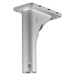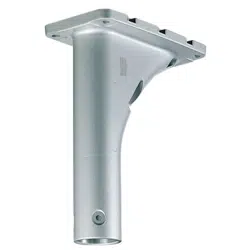
Step 2
Attach the cover of this product to the top of the camera.
Recommended tightening torque: 2.45 N·m {1.81 lbf·ft}
Note:
• Do not use the “cable cover”, when the “cable
cover” is provided with the camera.
• Use a 4 mm {5/32 inches} hexagon wrench
(locally procured) to tighten the camera fixing
screws (3 places).
• As shown in the illustration at right, put the
safety wire on the outside of the cover of this
product.
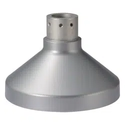
Step 3
Get the ceiling ready and attach the base of this product to the
ceiling.
Fixing screws: M8 screws
(flat washer / spring washer)
Minimum pullout strength: 1539 N {346 lbf} (per 1 pc.)
q Make screw holes or anchor holes in the ceiling,
and also wiring holes if necessary.
<Possible installation dimensions>
A: 71.8 mm × 71.8 mm {2-3/16 inches × 2-3/16 inches}
B: 120.5 mm × 120.5 mm {4-3/4 inches × 4-3/4 inches}
w When wiring through the ceiling, make a ø30 mm
{ø1-3/16 inches} hole in the center.
Cover
Camera fixing
screws (3 places)
Positioning
pin (3 places)
Safety wire
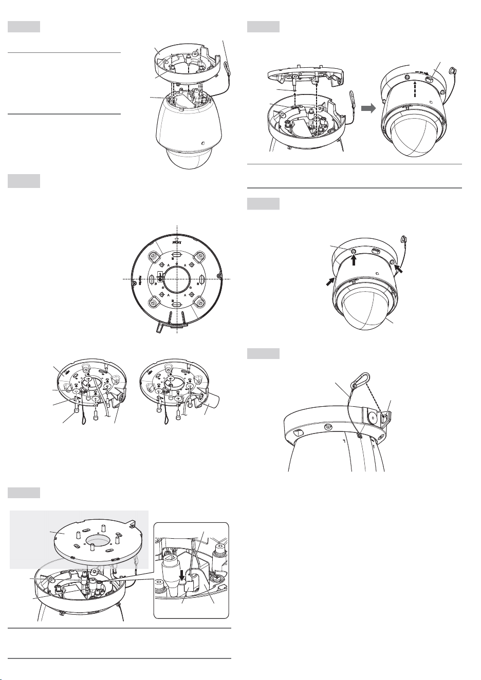
Step 5
Put the cover of this product which has been attached to the top
of the camera so the fitting holes (2 places) fit over the
positioning pins on the base that has been fixed to the ceiling, the
turn clockwise approximately 10° to temporarily fix in place.
Approx. 10°
Fitting hole
(2 places)
Positioning pin
(2 places)
Fitting hole (2 places)
Note:
• When temporarily fixing the camera to the base of this product, make sure you are holding
the cover of this product.
Step 6
Tighten the cover fixing screws (4 places) alternating diagonally
with a 4 mm {5/32 inches} hexagon wrench (locally procured) to
fix the cover attached to the camera to this product. (q to r)
Recommended tightening torque: 2.45 N·m {1.81 lbf·ft}
Fixing screws
for cover portion
(4 pleces)
q
w
e
r
<When wiring through the ceiling>
Base
Fixing screws (4 pcs.)
(M8: locally procured)
Cap for the
female thread
for the conduit
Flat washer (4 pcs.)
(M8: locally procured)
Spring washer (4 pcs.)
(M8: locally procured)
<When wiring through the side hole>
Conduit
When using the conduit on the ceiling for
wiring, remove the cap for the female thread
for the conduit by using a hexagon wrench
(ISO 2936, width across flats S=5 mm
{3/16 inches}).
The female thread for conduit is compliant
with ANSI NPSM (parallel pipe threads) 3/4
or ISO 228-1 (parallel pipe threads) G3/4.
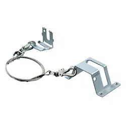
Step 4
Hang the camera from the base of this product with the installed
auxiliary wire and connect the cables.
Surface of the base
installed on the
ceiling
Installed
auxiliary
wire
Wire hook
Wire hookWire stopper
Installed auxiliary wire
Ceiling
Note:
• There are some cables to be connected that need to be waterproofed. Refer to the Installation
Guide for the camera for information on which cables need waterproofing and how to water-
proof them.
Step 7
Attach the safety wire of the camera to the wire hook section on
the base of this product.
Safety wire
Wire hook section
Refer to the Operating Instructions for the camera for information about further adjustments (con-
necting power to the camera, adjusting the angular field of view).
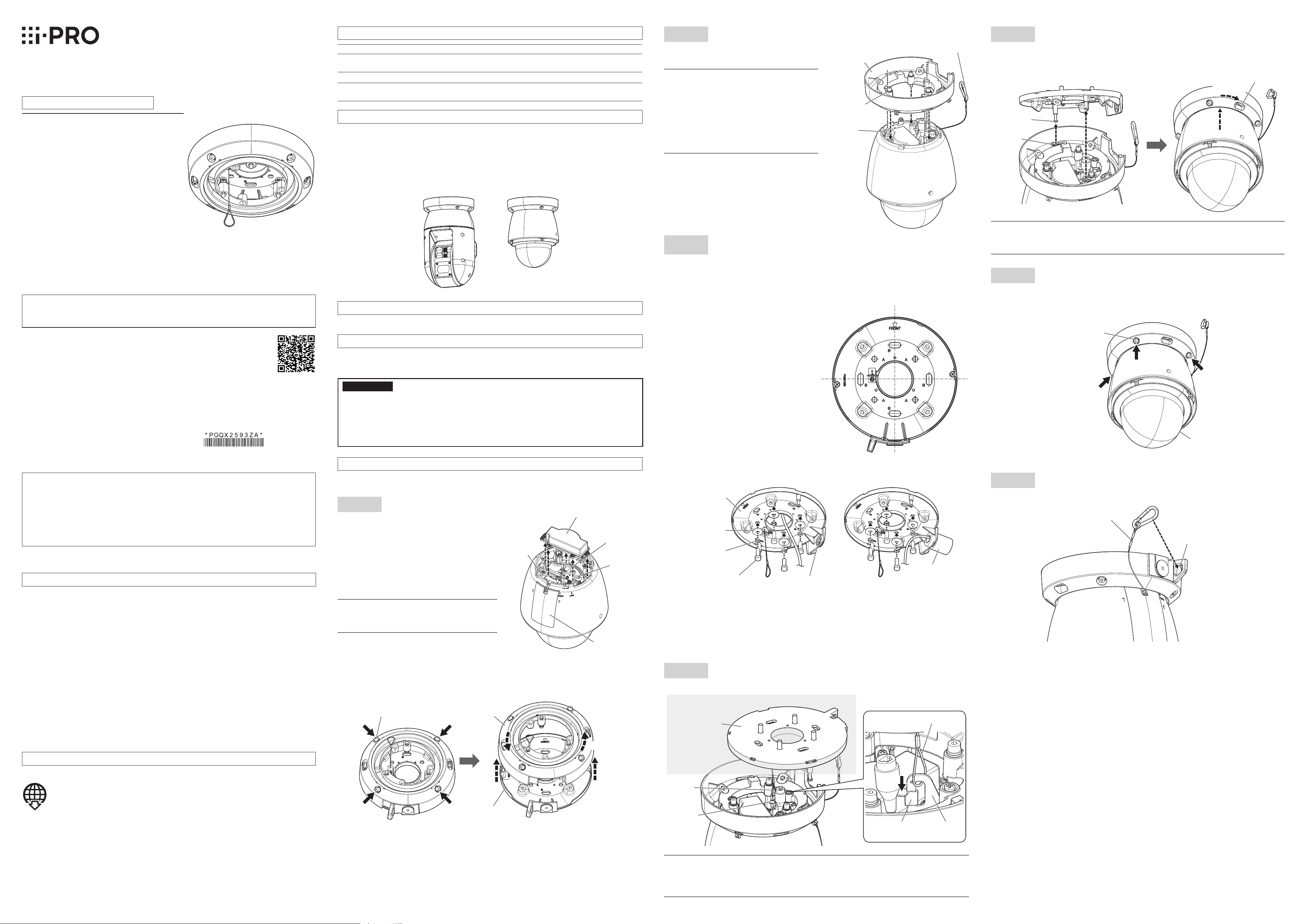
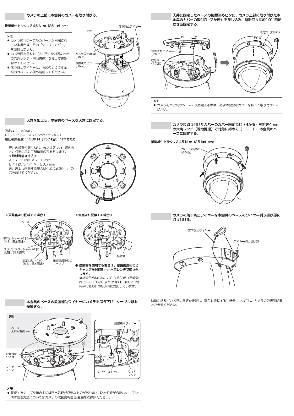
Installation
These instructions use the PTZ type camera to describe installation. Refer to the Installation Guide for
each camera for detailed installation information and procedures.
Step 1
Make preparations before installation.
Where necessary, remove the cable case
and insert an SD or microSD memory card.
When the only necessary connection to
camera is an Ethernet cable
Do not remove the cable case.
When using 24 V AC, EXT I/O device,
or audio input / output device
Remove the cable case.
Note:
• Waterproof the unused cables using the
waterproof tape (camera accessory).
Remove the cover from the base of this product.
q Loosen the cover fixing screws (4 places)
using a 4 mm {5/32 inches} hexagon wrench
(locally procured).
w Rotate the cover approximately 10°
counterclockwise and remove.
Cover fixing
screws (4 places)
Cover
Base
Approx. 10°
Main sunshield
rear cover
Power
cable
RJ45 (female)
Network cable
Alarm input/
output·
Audio input/
output cable
Cable case
IR PTZ camera series PTZ camera series
Ceiling Mount Bracket
Model No. WV-QCL500-S
WV-QCL500
Operating Instructions
Included Installation Instructions
Ns0522-0
Printed in China
• Before attempting to connect or install this product, please read these instructions carefully and
save this manual for future use.
• The external appearance and other parts shown in this manual may differ from the actual
product within the scope that will not interfere with normal use due to improvement of the
product.
Precaution
Refer installation work to the dealer.
Installation work requires technique and experience. Failure to observe this may cause fire, electric
shock, injury, or damage to the product.
Be sure to consult the dealer.
Install the product securely on a ceiling in accordance with the installation
instructions.
Failure to observe this may cause injury or accidents.
Do not use this bracket except with suitable cameras.
Failure to observe this may cause a drop resulting in injury or accidents.
Donotinstallthisproductonaplacethatisgreatlyin�uencedbywind.
Installation on a place where the wind speed is 60 m/s {approx. 134 mph} or more may cause a
fall of the product resulting in injury or accidents.
When using this product, also read the “Precautions” described in the operating
instructions for the camera to be attached.
i-PRO Co., Ltd. assumes no responsibility for injuries or property damage resulting
from failures arising out of improper installation or operation inconsistent with this
documentation.
Caution:
• Before attempting to connect or operate this
product, please read these instructions care-
fully.
Notice:
• This product is not suitable for use in loca-
tions where children are likely to be present.
• Do not install this product in locations where
ordinary persons can easily reach.
• For information about screws and other
parts required for installation, refer to the
corresponding section of this document.
© i-PRO Co., Ltd. 2022
"<Control No.: C****>" used in these documents should be used to search for
information on our technical information website (https://i-pro.com/global/en/surveillance/
training-support/support/technical-information) and will guide you to the right information.
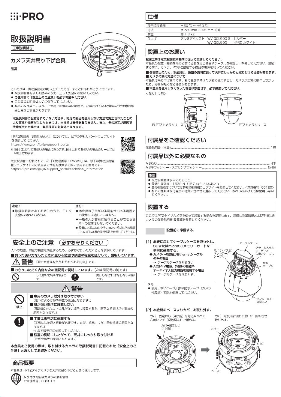
Specifications
Ambient operating temperature: –50 °C to +60 °C {–58 °F to +140 °F}
Dimensions: ø229 mm × 55 mm (H)
{ø9-1/32 inches × 2-5/32 inches (H)}
Mass: Approx. 1.3 kg {2.87 lbs}
Finish: Aluminum die cast WV-QCL500-S : Silver
WV-QCL500 : i-PRO white
Precautions for installation
In order to prevent injury, the product must be securely mounted to the ceiling
according to the Installation Guide of this bracket.
Mounting method for this product
This product is designed to be used as a pendant mount camera. If the product is mounted on a
desktop or at a slant, the camera may not work correctly and its lifetime may be shortened.
Make sure to remove this product if it will no longer be used.
<Installation example>
Standard accessories
Operating Instructions (this document) ..........................................................................................1 pc.
Other items that are needed (not included)
M8 screw .................................................................................................................................. 4 pcs.
M8 flat washer / spring washer .................................................................................... 4 pcs. for each
IMPORTANT
• The installation surface is horizontal.
• Minimum pullout strength: 1539 N {346 lbf} (per 1 pc.)
• This value indicates the minimum pull-out strength required value per screw. For information about
the minimum pull-out strength, refer to our technical information website <Control No.: C0120>.
• Select screws according to the material of the location that the camera will be mounted to.
In this case, wood screws and nails should not be used.
i-PRO Co., Ltd.
https://www.i-pro.com/
Preface
This product is used to mount the PTZ type camera on the ceiling.
The latest information about the supported cameras
<Control No.: C0501>
Step 2
Attach the cover of this product to the top of the camera.
Recommended tightening torque: 2.45 N·m {1.81 lbf·ft}
Note:
• Do not use the “cable cover”, when the “cable
cover” is provided with the camera.
• Use a 4 mm {5/32 inches} hexagon wrench
(locally procured) to tighten the camera fixing
screws (3 places).
• As shown in the illustration at right, put the
safety wire on the outside of the cover of this
product.
Step 3
Get the ceiling ready and attach the base of this product to the
ceiling.
Fixing screws: M8 screws
(flat washer / spring washer)
Minimum pullout strength: 1539 N {346 lbf} (per 1 pc.)
q Make screw holes or anchor holes in the ceiling,
and also wiring holes if necessary.
<Possible installation dimensions>
A: 71.8 mm × 71.8 mm {2-3/16 inches × 2-3/16 inches}
B: 120.5 mm × 120.5 mm {4-3/4 inches × 4-3/4 inches}
w When wiring through the ceiling, make a ø30 mm
{ø1-3/16 inches} hole in the center.
Cover
Camera fixing
screws (3 places)
Positioning
pin (3 places)
Safety wire
Step 5
Put the cover of this product which has been attached to the top
of the camera so the fitting holes (2 places) fit over the
positioning pins on the base that has been fixed to the ceiling, the
turn clockwise approximately 10° to temporarily fix in place.
Approx. 10°
Fitting hole
(2 places)
Positioning pin
(2 places)
Fitting hole (2 places)
Note:
• When temporarily fixing the camera to the base of this product, make sure you are holding
the cover of this product.
Step 6
Tighten the cover fixing screws (4 places) alternating diagonally
with a 4 mm {5/32 inches} hexagon wrench (locally procured) to
fix the cover attached to the camera to this product. (q to r)
Recommended tightening torque: 2.45 N·m {1.81 lbf·ft}
Fixing screws
for cover portion
(4 pleces)
q
w
e
r
<When wiring through the ceiling>
Base
Fixing screws (4 pcs.)
(M8: locally procured)
Cap for the
female thread
for the conduit
Flat washer (4 pcs.)
(M8: locally procured)
Spring washer (4 pcs.)
(M8: locally procured)
<When wiring through the side hole>
Conduit
When using the conduit on the ceiling for
wiring, remove the cap for the female thread
for the conduit by using a hexagon wrench
(ISO 2936, width across flats S=5 mm
{3/16 inches}).
The female thread for conduit is compliant
with ANSI NPSM (parallel pipe threads) 3/4
or ISO 228-1 (parallel pipe threads) G3/4.
Step 4
Hang the camera from the base of this product with the installed
auxiliary wire and connect the cables.
Surface of the base
installed on the
ceiling
Installed
auxiliary
wire
Wire hook
Wire hookWire stopper
Installed auxiliary wire
Ceiling
Note:
• There are some cables to be connected that need to be waterproofed. Refer to the Installation
Guide for the camera for information on which cables need waterproofing and how to water-
proof them.
Step 7
Attach the safety wire of the camera to the wire hook section on
the base of this product.
Safety wire
Wire hook section
Refer to the Operating Instructions for the camera for information about further adjustments (con-
necting power to the camera, adjusting the angular field of view).
Installation
These instructions use the PTZ type camera to describe installation. Refer to the Installation Guide for
each camera for detailed installation information and procedures.
Step 1
Make preparations before installation.
Where necessary, remove the cable case
and insert an SD or microSD memory card.
When the only necessary connection to
camera is an Ethernet cable
Do not remove the cable case.
When using 24 V AC, EXT I/O device,
or audio input / output device
Remove the cable case.
Note:
• Waterproof the unused cables using the
waterproof tape (camera accessory).
Remove the cover from the base of this product.
q Loosen the cover fixing screws (4 places)
using a 4 mm {5/32 inches} hexagon wrench
(locally procured).
w Rotate the cover approximately 10°
counterclockwise and remove.
Cover fixing
screws (4 places)
Cover
Base
Approx. 10°
Main sunshield
rear cover
Power
cable
RJ45 (female)
Network cable
Alarm input/
output·
Audio input/
output cable
Cable case
IR PTZ camera series PTZ camera series
Ceiling Mount Bracket
Model No. WV-QCL500-S
WV-QCL500
Operating Instructions
Included Installation Instructions
Ns0522-0
Printed in China
• Before attempting to connect or install this product, please read these instructions carefully and
save this manual for future use.
• The external appearance and other parts shown in this manual may differ from the actual
product within the scope that will not interfere with normal use due to improvement of the
product.
Precaution
Refer installation work to the dealer.
Installation work requires technique and experience. Failure to observe this may cause fire, electric
shock, injury, or damage to the product.
Be sure to consult the dealer.
Install the product securely on a ceiling in accordance with the installation
instructions.
Failure to observe this may cause injury or accidents.
Do not use this bracket except with suitable cameras.
Failure to observe this may cause a drop resulting in injury or accidents.
Donotinstallthisproductonaplacethatisgreatlyin�uencedbywind.
Installation on a place where the wind speed is 60 m/s {approx. 134 mph} or more may cause a
fall of the product resulting in injury or accidents.
When using this product, also read the “Precautions” described in the operating
instructions for the camera to be attached.
i-PRO Co., Ltd. assumes no responsibility for injuries or property damage resulting
from failures arising out of improper installation or operation inconsistent with this
documentation.
Caution:
• Before attempting to connect or operate this
product, please read these instructions care-
fully.
Notice:
• This product is not suitable for use in loca-
tions where children are likely to be present.
• Do not install this product in locations where
ordinary persons can easily reach.
• For information about screws and other
parts required for installation, refer to the
corresponding section of this document.
© i-PRO Co., Ltd. 2022
"<Control No.: C****>" used in these documents should be used to search for
information on our technical information website (https://i-pro.com/global/en/surveillance/
training-support/support/technical-information) and will guide you to the right information.
Specifications
Ambient operating temperature: –50 °C to +60 °C {–58 °F to +140 °F}
Dimensions: ø229 mm × 55 mm (H)
{ø9-1/32 inches × 2-5/32 inches (H)}
Mass: Approx. 1.3 kg {2.87 lbs}
Finish: Aluminum die cast WV-QCL500-S : Silver
WV-QCL500 : i-PRO white
Precautions for installation
In order to prevent injury, the product must be securely mounted to the ceiling
according to the Installation Guide of this bracket.
Mounting method for this product
This product is designed to be used as a pendant mount camera. If the product is mounted on a
desktop or at a slant, the camera may not work correctly and its lifetime may be shortened.
Make sure to remove this product if it will no longer be used.
<Installation example>
Standard accessories
Operating Instructions (this document) ..........................................................................................1 pc.
Other items that are needed (not included)
M8 screw .................................................................................................................................. 4 pcs.
M8 flat washer / spring washer .................................................................................... 4 pcs. for each
IMPORTANT
• The installation surface is horizontal.
• Minimum pullout strength: 1539 N {346 lbf} (per 1 pc.)
• This value indicates the minimum pull-out strength required value per screw. For information about
the minimum pull-out strength, refer to our technical information website <Control No.: C0120>.
• Select screws according to the material of the location that the camera will be mounted to.
In this case, wood screws and nails should not be used.
i-PRO Co., Ltd.
https://www.i-pro.com/
Preface
This product is used to mount the PTZ type camera on the ceiling.
The latest information about the supported cameras
<Control No.: C0501>
WV-QCL500-S
WV-QCL500
Step 2
Step 3
q
w
Step 5
Step 6
q r
q
w
e
r
Step 4
Step 7
Step 1
q w
i-PRO株式会社
https://www.i-pro.com/
WV-QCL500-S
WV-QCL500
Step 2
Step 3
q
w
Step 5
Step 6
q r
q
w
e
r
Step 4
Step 7
Step 1
q w
i-PRO株式会社
https://www.i-pro.com/