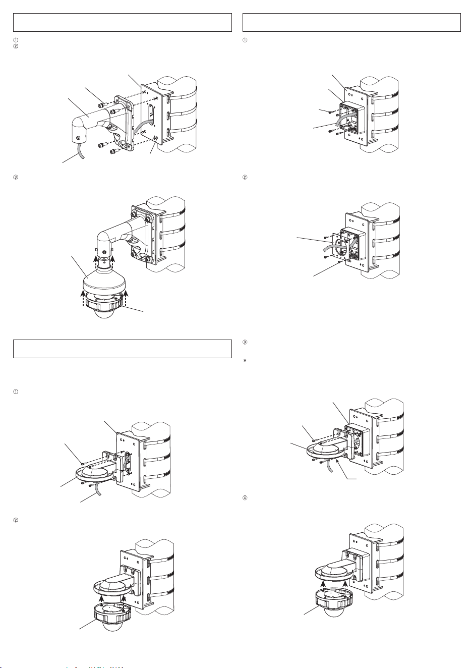
② Pass the support band (accessory) through the access hole of fixing band (upper) to temporarily
fix this product onto the pole to be installed.
IMPORTANT:
• To prevent this product sliding down,
please pull the support band tightly to
temporarily fix it.
Note:
• During installation, please note that the
cable is not placed between this
product and the pole.
• Please confirm the installation height
after considering the height of installing
camera onto this product.
③ Take out one fixing band and pass it through access hole of fixing band (middle), then use a torque
wrench (locally procured) to tighten the fixing band lock screw in a clockwise direction to completely
fix this product. Then take out another fixing band and pass it through access hole of fixing band
(lower), and fix it in the same way.
(Recommended tightening torque of fixing band: 5 N·m {3.69 lbf·ft})
Note:
• During installation, please rotate fixing
band to adjust its position and make sure
the fixing band lock screw is located on the
surface of the pole.
• When passing through the access hole of
fixing band of this product, please pay
attention not to pinch the cable between
the fixing band and pole.
Operating Instructions (this document) ......................................................................................... 1 pc.
Fixing bands .............................................................................................................................. 3 pcs.
Support band .............................................................................................................................. 1 pc.
Use the following accessories as the installation requires (use of all accessories together will likely not
be necessary):
Safety wire fixing bracket ............................................................................................................. 1 pc.
M10 × 30 mm {1-3/16 inches} hexagon screws ........................................................................ 5 pcs.
M6 × 16 mm {5/8 inches} hexagon screws ................................................................................ 2 pcs.
M4 × 20 mm {25/32 inches} hexagon screws ............................................................................ 5 pcs.
Note:
• One spare is provided for each type of screw.
• In order to tighten the fixing bands during installation, it's necessary to use torque wrench (locally
procured).
• Each 8 mm {5/16 inches}, 5 mm {3/16 inches} or 3 mm {1/8 inches} hexagon wrench (locally
procured) is needed when M10, M6 or M4 hexagon screw is used.
(In this manual, hexagon socket head cap screw is described as hexagon screw.)
Please wear gloves during installation. Cutting off fixing bands may cut your fingers.
① Pass the cable to be connected with camera
through the cable access hole of this product
and pull out an adequate length as needed for
the camera.
Note:
• Please choose to wring port upward
or downward as per the site situation.
This manual illustrates the example
with the wiring port downward.
⑤ For the remaining part of fixing bands, leave approximate 70 mm {2-3/4 inches} in the part of
fixing band lock screw and use a tool (locally procured) to cut off the remaining part. Please treat
the cut-off part to prevent injury.
From the pole to be
installed
Access hole of fixing
band (lower)
Access hole of fixing
band (middle)
④ Cut and remove the support band. Fix the last access hole of fixing band (upper) in the same way.
(Recommended tightening torque of fixing band: 5 N·m {3.69 lbf·ft})
Note:
• After finishing the installation, please
confirm there is no looseness or inclina-
tion for fixing bands.
Access hole of fixing
band (upper)
Support band
(accessory)
Install the mount bracket onto a vertical pole
Operating Instructions
Included Installation Instructions
Pole Mount Bracket
Model No. WV-QPL500-W
© i-PRO Co., Ltd. 2022
• Before attempting to connect or install this product, please read these instructions carefully and
save this manual for future use.
• The external appearance and other parts shown in this manual may differ from the actual product
within the scope that will not interfere with normal use due to improvement of the product.
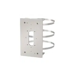
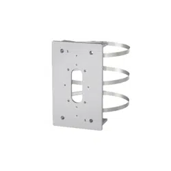
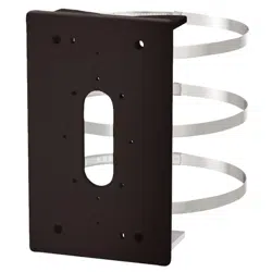
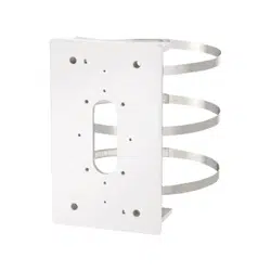
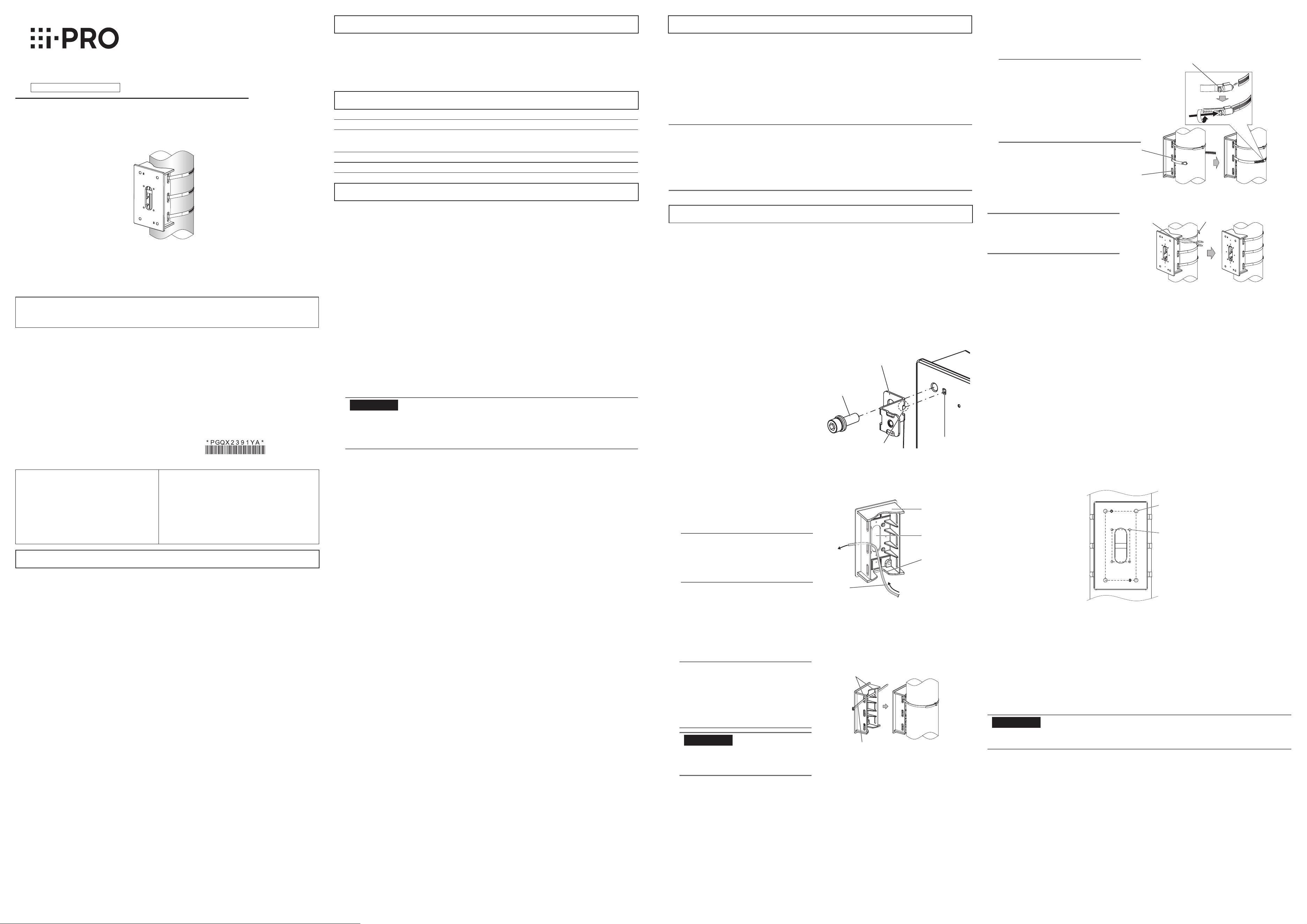
This product is designed to be used to install a camera or mount bracket for camera to a vertical
round pole with diameter from 80 mm {3-5/32 inches} to 200 mm {7-7/8 inches}.
For the latest information about the mountable models, refer to our support website
(https://i-pro.com/global/en/surveillance/training_support/support/technical_information
<Control No.:C0501, 0502>).
Ambient operating temperature: –50 °C to +60 °C {–58 °F to 140 °F}
Dimensions: 140 mm (W) × 230 mm (H) × 70 mm (D)
{5-1/2 inches (W) × 9-1/16 inches (H) × 2-3/4 inches (D)}
Mass: Approx. 1.2 kg {2.65 lbs}
Finish: Aluminum die cast i-PRO White
Do not hang down from this product or use this product as a pedestal.
Failure to observe this may cause injury or accidents.
Do not use this bracket except with specified cameras or mount brackets.
Failure to observe this may cause a drop resulting in injury or accidents.
Do not install this product on a place that is greatly influenced by wind.
Installation on a place where the wind speed is 60 m/s {approx. 134 mph} or more may cause a fall
of the product resulting in injury or accidents.
Refer installation work to the dealer.
Installation work requires technique and experiences. Failure to observe this may cause fire, electric
shock, injury, or damage to the product.
Be sure to consult the dealer.
The exclusively designed mount bracket shall be used.
Failure to observe this may cause a drop resulting in injury or accidents.
Use the exclusively designed mount bracket for installation.
The measures of protection against a fall of this product shall be taken.
Failure to observe this may cause a drop resulting in injury.
If there is specified safety wire, please make sure to install it.
The measures of protection against snowfall shall be taken.
Weight of snow may cause a fall of the product resulting in injury or accidents. Protect the product
against snowfall by installing it under eaves.
Do not rub the edges of metal parts with your hand.
Strong rubbing may cause injury.
When using this product, also read the “Precautions” described in the operating
instructions for the camera to be attached.
In order to prevent injury, the product must be securely mounted to the pole
according to Operating Instructions.
About installable pole
• Please consider the influence of vibration and wind at the installation site and mount the bracket
onto the poles with appropriate strength.
Installable pole: round (ø80 mm ~ ø200 mm {ø3-5/32 inches ~ ø7-7/8 inches})
• Please do not mount it onto a pole made of wood or resin with low endurance or quality having
changed after experiencing years' time.
• After the bracket is mounted, please verify the following content once a year. In the event of
abnormality, please inform the dealer or the constructor.
Do not allow any slanting, distortion or offset in installation.
Bracket and fixing band should not have any serious rust or damage.
• Please refer to our support website https://i-pro.com/global/en/surveillance/training_support/
support/technical_information <Control No.:C0507> for installation information of the bracket.
About the installation methods
• The bracket is specifically designed for installation onto a round pole.
• Fix the bracket to a pole by tightening the screws of three fixing bands. Please make sure to fix
firmly with the following tightening torque.
(Recommended tightening torque: 5 N·m {3.69 lbf·ft})
IMPORTANT:
• Please do not exceed the torque limit when tightening the screw. Excessive tightening may
damage the screw of the fixing band. Please do not use a fixing band with damaged
tightening screw.
Limited tightening torque: 7.5 N·m {5.53 lbf·ft}
• For the pole, install the fixing band vertically. An slanted installation of the fixing band will result in
excessive slack which could lead to a fall.
• When installing, please pay attention to not damage any part that influences the strength of the
fixing band.
• When the pole mount bracket is installed to a pole with easy gliding painting or coating, please
pay attention to rotating and sliding down.
• After the installation is finished, please check if there are deviations related to slackness, fitting
and rotation of the fixing band.
In the event of abnormality, please tighten again.
Check before the installation.
Once the bracket is installed with a deformed mount bracket and/or damaged part, it could
potentially fall. Before the installation, please make sure to check the appearance of the bracket and
the fixing band.
Screw tightening
• Make sure to tighten the screws (accessory) that fix camera or mount bracket onto this product.
• Do not use an impact driver. Use of an impact driver may damage the screws or cause tightening
excessively.
• When a screw is tightened, make the screw at a right angle to the surface. After tightening the
screws or bolts, perform checks to ensure that the tightening is sufficient enough so that there is
no movement or looseness.
Make sure to remove this product if it will no longer be used.
WV-QPL500-W
(This product)
Cable access hole
Wiring port
Cable
Access hole of fixing
band (upper)
Support band
(accessory)
Fixing band lock screw
i-PRO Co., Ltd. assumes no responsibility for injuries or property damage
resulting from failures arising out of improper installation or operation
inconsistent with this documentation.
Caution:
• Before attempting to connect or operate
this product, please read these
instructions carefully.
Notice:
• This product is not suitable for use in locations
where children are likely to be present.
• Do not install this product in locations where
ordinary persons can easily reach.
• For information about screws and brackets
required for installation, refer to the
corresponding section of this document.
Precautions
Preface Standard accessories
Installations
Precautions for installation
Specifications
Before mounting the camera, attach the safety wire fixing bracket to this product.
• Use one M10 × 30 mm {1-3/16 inches} hexagon screw (accessory) to install the safety wire fixing
bracket (accessory) on the top left corner of this product.
(Recommended tightening torque: 10.8 N·m {7.97 lbf·ft})
Size: 180 mm (H) × 80 mm (W)
{7-3/32 inches (H) × 3-5/32 inches (W)}
M10 screw hole (4 places)
Size: 83.5 mm (H) × 46 mm (W)
{3-9/32 inches (H) × 1-13/16 inches (W)}
M4 screw hole (4 places)
Size for installation side
Install camera or mount bracket for camera to pole mount bracket
When the camera is directly attached to this product and the camera equipped
with a safety wire.
Size illustration for installing part of WV-QPL500-W
<Mountable models>
You can attach the camera directly to this product, or attach the camera by using the following
bracket combination.
- WV-QWL501-W (Wall Mount Bracket: i-PRO White)
- WV-QSR501-W (Mount Bracket : i-PRO White)
- WV-QWL500-W (Wall Mount Bracket: i-PRO White)
- WV-QJB500-W (Adapter Box: i-PRO White)
For the latest information about the mountable models, refer to our support web site
(https://i-pro.com/global/en/surveillance/training_support/support/technical_information
<Control No.:C0501
,
C0502>).
IMPORTANT:
• Only one bracket and camera can be installed with this product. Do not install any bracket or
camera which is not described in the manual (this document) or our support website.
Please choose one appropriate way from the following five installation methods according to the
camera to be installed. For the cables connected to camera, please refer to the operating instructions
of camera.
When mounting an outdoor dome type camera
Ⓐ Mount the camera by using this product with WV-QWL501-W and WV-QSR501-W.
Ⓑ Mount the camera by using this product and WV-QWL500-W.
Ⓒ Mount the camera by using this product with WV-QWL500-W and WV-QJB500-W.
When mounting an outdoor box type camera
Ⓓ Directly mount the camera to this product.
Ⓔ Mount the camera by using this product and WV-QJB500-W.
As for the mounting steps from Ⓐ to Ⓔ, refer to the back side of this document and the operating
instructions of each bracket and camera.
M10 × 30 mm {1-3/16 inches}
hexagon screw (accessory)
Ls0620-1042
Printed in China
Be sure to read “Precautions” and “Precautions for installation” before installation.
Refer to the operating instructions of the camera for details on the camera installation
(including the camera mounting, cable connection and adjustment).
Locating hole
Prominence of safety
wire fixing bracket
Safety wire fixing bracket
(accessory)
For U.S. and Canada:
i-PRO Americas Inc.
For Europe and other countries:
i-PRO EMEA B.V.
https://www.i-pro.com/
② Pass the support band (accessory) through the access hole of fixing band (upper) to temporarily
fix this product onto the pole to be installed.
IMPORTANT:
• To prevent this product sliding down,
please pull the support band tightly to
temporarily fix it.
Note:
• During installation, please note that the
cable is not placed between this
product and the pole.
• Please confirm the installation height
after considering the height of installing
camera onto this product.
③ Take out one fixing band and pass it through access hole of fixing band (middle), then use a torque
wrench (locally procured) to tighten the fixing band lock screw in a clockwise direction to completely
fix this product. Then take out another fixing band and pass it through access hole of fixing band
(lower), and fix it in the same way.
(Recommended tightening torque of fixing band: 5 N·m {3.69 lbf·ft})
Note:
• During installation, please rotate fixing
band to adjust its position and make sure
the fixing band lock screw is located on the
surface of the pole.
• When passing through the access hole of
fixing band of this product, please pay
attention not to pinch the cable between
the fixing band and pole.
Operating Instructions (this document) ......................................................................................... 1 pc.
Fixing bands .............................................................................................................................. 3 pcs.
Support band .............................................................................................................................. 1 pc.
Use the following accessories as the installation requires (use of all accessories together will likely not
be necessary):
Safety wire fixing bracket ............................................................................................................. 1 pc.
M10 × 30 mm {1-3/16 inches} hexagon screws ........................................................................ 5 pcs.
M6 × 16 mm {5/8 inches} hexagon screws ................................................................................ 2 pcs.
M4 × 20 mm {25/32 inches} hexagon screws ............................................................................ 5 pcs.
Note:
• One spare is provided for each type of screw.
• In order to tighten the fixing bands during installation, it's necessary to use torque wrench (locally
procured).
• Each 8 mm {5/16 inches}, 5 mm {3/16 inches} or 3 mm {1/8 inches} hexagon wrench (locally
procured) is needed when M10, M6 or M4 hexagon screw is used.
(In this manual, hexagon socket head cap screw is described as hexagon screw.)
Please wear gloves during installation. Cutting off fixing bands may cut your fingers.
① Pass the cable to be connected with camera
through the cable access hole of this product
and pull out an adequate length as needed for
the camera.
Note:
• Please choose to wring port upward
or downward as per the site situation.
This manual illustrates the example
with the wiring port downward.
⑤ For the remaining part of fixing bands, leave approximate 70 mm {2-3/4 inches} in the part of
fixing band lock screw and use a tool (locally procured) to cut off the remaining part. Please treat
the cut-off part to prevent injury.
From the pole to be
installed
Access hole of fixing
band (lower)
Access hole of fixing
band (middle)
④ Cut and remove the support band. Fix the last access hole of fixing band (upper) in the same way.
(Recommended tightening torque of fixing band: 5 N·m {3.69 lbf·ft})
Note:
• After finishing the installation, please
confirm there is no looseness or inclina-
tion for fixing bands.
Access hole of fixing
band (upper)
Support band
(accessory)
Install the mount bracket onto a vertical pole
Operating Instructions
Included Installation Instructions
Pole Mount Bracket
Model No. WV-QPL500-W
© i-PRO Co., Ltd. 2022
• Before attempting to connect or install this product, please read these instructions carefully and
save this manual for future use.
• The external appearance and other parts shown in this manual may differ from the actual product
within the scope that will not interfere with normal use due to improvement of the product.
This product is designed to be used to install a camera or mount bracket for camera to a vertical
round pole with diameter from 80 mm {3-5/32 inches} to 200 mm {7-7/8 inches}.
For the latest information about the mountable models, refer to our support website
(https://i-pro.com/global/en/surveillance/training_support/support/technical_information
<Control No.:C0501, 0502>).
Ambient operating temperature: –50 °C to +60 °C {–58 °F to 140 °F}
Dimensions: 140 mm (W) × 230 mm (H) × 70 mm (D)
{5-1/2 inches (W) × 9-1/16 inches (H) × 2-3/4 inches (D)}
Mass: Approx. 1.2 kg {2.65 lbs}
Finish: Aluminum die cast i-PRO White
Do not hang down from this product or use this product as a pedestal.
Failure to observe this may cause injury or accidents.
Do not use this bracket except with specified cameras or mount brackets.
Failure to observe this may cause a drop resulting in injury or accidents.
Do not install this product on a place that is greatly influenced by wind.
Installation on a place where the wind speed is 60 m/s {approx. 134 mph} or more may cause a fall
of the product resulting in injury or accidents.
Refer installation work to the dealer.
Installation work requires technique and experiences. Failure to observe this may cause fire, electric
shock, injury, or damage to the product.
Be sure to consult the dealer.
The exclusively designed mount bracket shall be used.
Failure to observe this may cause a drop resulting in injury or accidents.
Use the exclusively designed mount bracket for installation.
The measures of protection against a fall of this product shall be taken.
Failure to observe this may cause a drop resulting in injury.
If there is specified safety wire, please make sure to install it.
The measures of protection against snowfall shall be taken.
Weight of snow may cause a fall of the product resulting in injury or accidents. Protect the product
against snowfall by installing it under eaves.
Do not rub the edges of metal parts with your hand.
Strong rubbing may cause injury.
When using this product, also read the “Precautions” described in the operating
instructions for the camera to be attached.
In order to prevent injury, the product must be securely mounted to the pole
according to Operating Instructions.
About installable pole
• Please consider the influence of vibration and wind at the installation site and mount the bracket
onto the poles with appropriate strength.
Installable pole: round (ø80 mm ~ ø200 mm {ø3-5/32 inches ~ ø7-7/8 inches})
• Please do not mount it onto a pole made of wood or resin with low endurance or quality having
changed after experiencing years' time.
• After the bracket is mounted, please verify the following content once a year. In the event of
abnormality, please inform the dealer or the constructor.
Do not allow any slanting, distortion or offset in installation.
Bracket and fixing band should not have any serious rust or damage.
• Please refer to our support website https://i-pro.com/global/en/surveillance/training_support/
support/technical_information <Control No.:C0507> for installation information of the bracket.
About the installation methods
• The bracket is specifically designed for installation onto a round pole.
• Fix the bracket to a pole by tightening the screws of three fixing bands. Please make sure to fix
firmly with the following tightening torque.
(Recommended tightening torque: 5 N·m {3.69 lbf·ft})
IMPORTANT:
• Please do not exceed the torque limit when tightening the screw. Excessive tightening may
damage the screw of the fixing band. Please do not use a fixing band with damaged
tightening screw.
Limited tightening torque: 7.5 N·m {5.53 lbf·ft}
• For the pole, install the fixing band vertically. An slanted installation of the fixing band will result in
excessive slack which could lead to a fall.
• When installing, please pay attention to not damage any part that influences the strength of the
fixing band.
• When the pole mount bracket is installed to a pole with easy gliding painting or coating, please
pay attention to rotating and sliding down.
• After the installation is finished, please check if there are deviations related to slackness, fitting
and rotation of the fixing band.
In the event of abnormality, please tighten again.
Check before the installation.
Once the bracket is installed with a deformed mount bracket and/or damaged part, it could
potentially fall. Before the installation, please make sure to check the appearance of the bracket and
the fixing band.
Screw tightening
• Make sure to tighten the screws (accessory) that fix camera or mount bracket onto this product.
• Do not use an impact driver. Use of an impact driver may damage the screws or cause tightening
excessively.
• When a screw is tightened, make the screw at a right angle to the surface. After tightening the
screws or bolts, perform checks to ensure that the tightening is sufficient enough so that there is
no movement or looseness.
Make sure to remove this product if it will no longer be used.
WV-QPL500-W
(This product)
Cable access hole
Wiring port
Cable
Access hole of fixing
band (upper)
Support band
(accessory)
Fixing band lock screw
i-PRO Co., Ltd. assumes no responsibility for injuries or property damage
resulting from failures arising out of improper installation or operation
inconsistent with this documentation.
Caution:
• Before attempting to connect or operate
this product, please read these
instructions carefully.
Notice:
• This product is not suitable for use in locations
where children are likely to be present.
• Do not install this product in locations where
ordinary persons can easily reach.
• For information about screws and brackets
required for installation, refer to the
corresponding section of this document.
Precautions
Preface Standard accessories
Installations
Precautions for installation
Specifications
Before mounting the camera, attach the safety wire fixing bracket to this product.
• Use one M10 × 30 mm {1-3/16 inches} hexagon screw (accessory) to install the safety wire fixing
bracket (accessory) on the top left corner of this product.
(Recommended tightening torque: 10.8 N·m {7.97 lbf·ft})
Size: 180 mm (H) × 80 mm (W)
{7-3/32 inches (H) × 3-5/32 inches (W)}
M10 screw hole (4 places)
Size: 83.5 mm (H) × 46 mm (W)
{3-9/32 inches (H) × 1-13/16 inches (W)}
M4 screw hole (4 places)
Size for installation side
Install camera or mount bracket for camera to pole mount bracket
When the camera is directly attached to this product and the camera equipped
with a safety wire.
Size illustration for installing part of WV-QPL500-W
<Mountable models>
You can attach the camera directly to this product, or attach the camera by using the following
bracket combination.
- WV-QWL501-W (Wall Mount Bracket: i-PRO White)
- WV-QSR501-W (Mount Bracket : i-PRO White)
- WV-QWL500-W (Wall Mount Bracket: i-PRO White)
- WV-QJB500-W (Adapter Box: i-PRO White)
For the latest information about the mountable models, refer to our support web site
(https://i-pro.com/global/en/surveillance/training_support/support/technical_information
<Control No.:C0501
,
C0502>).
IMPORTANT:
• Only one bracket and camera can be installed with this product. Do not install any bracket or
camera which is not described in the manual (this document) or our support website.
Please choose one appropriate way from the following five installation methods according to the
camera to be installed. For the cables connected to camera, please refer to the operating instructions
of camera.
When mounting an outdoor dome type camera
Ⓐ Mount the camera by using this product with WV-QWL501-W and WV-QSR501-W.
Ⓑ Mount the camera by using this product and WV-QWL500-W.
Ⓒ Mount the camera by using this product with WV-QWL500-W and WV-QJB500-W.
When mounting an outdoor box type camera
Ⓓ Directly mount the camera to this product.
Ⓔ Mount the camera by using this product and WV-QJB500-W.
As for the mounting steps from Ⓐ to Ⓔ, refer to the back side of this document and the operating
instructions of each bracket and camera.
M10 × 30 mm {1-3/16 inches}
hexagon screw (accessory)
Ls0620-1042
Printed in China
Be sure to read “Precautions” and “Precautions for installation” before installation.
Refer to the operating instructions of the camera for details on the camera installation
(including the camera mounting, cable connection and adjustment).
Locating hole
Prominence of safety
wire fixing bracket
Safety wire fixing bracket
(accessory)
For U.S. and Canada:
i-PRO Americas Inc.
For Europe and other countries:
i-PRO EMEA B.V.
https://www.i-pro.com/
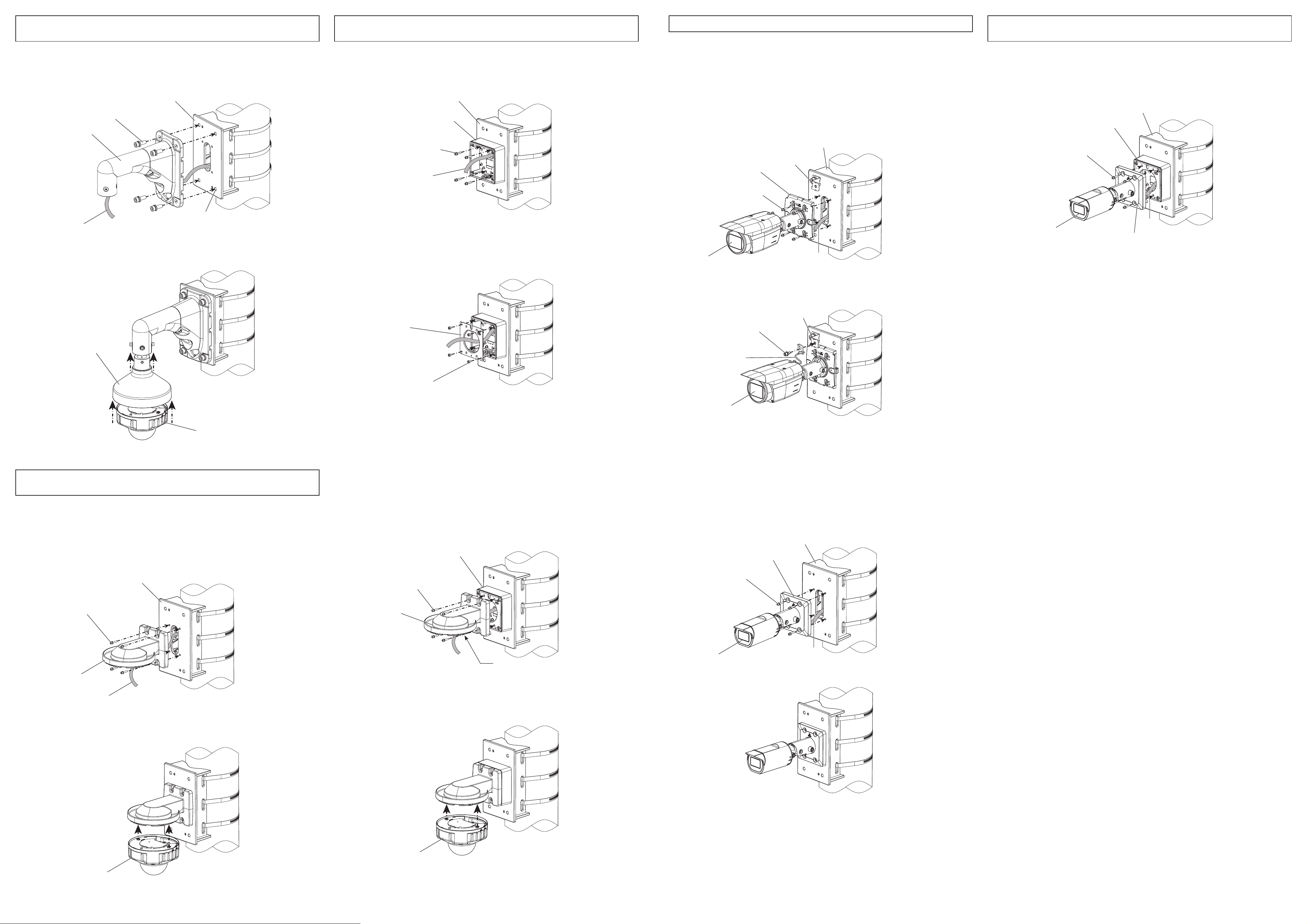
Pass the cable coming from this product through WV-QWL501-W.
Adjust the hole of WV-QWL501-W (4 places) to the M10 screw holes (4 places) and then fix them
with the M10 × 30 mm {1-3/16 inches} hexagon screws (4 pcs.) (accessories).
(Recommended tightening torque: 10.8 N·m {7.97 lbf·ft})
Pass the cable coming from this product through the base bracket of WV-QJB500-W and fix the
base bracket of WV-QJB500-W by using M4 × 20 mm {25/32 inches} hexagon screws (4 pcs.)
(accessory).
(Recommended tightening torque: 1.37 N·m {1.01 lbf·ft})
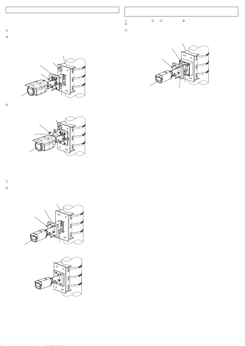
<In case of the camera with a square shaped camera mount bracket and a safety wire>
For details about how to install the safety wire fixing bracket, refer to "
When the camera is
directly attached to this product and the camera equipped with a safety wire."
Connect the cable coming from this product to the camera. For details about the connection and
waterproofing, refer to the operating instructions of the camera.
Align the four installation holes of camera mount bracket with the M4 screw holes (4 places) of this
product, and fix the camera with M4 × 20 mm {25/32 inches} hexagon screws (4 pcs.) (accessory).
(Recommended tightening torque: 1.37 N·m {1.01 lbf·ft})
For the fixing of camera and installation of camera mount bracket cover (accessory attached with the
camera), please refer to the operating instructions of the camera.
Use one M6 × 16 mm {5/8 inches} hexagon screw (accessory) to fix the safety wire of the camera
onto the safety wire fixing bracket (accessory).
(Recommended tightening torque: 2.45 N·m {1.81 lbf·ft})
By referring to steps and of the procedure , attach WV-QJB500-W to this product.
As described in the operating instructions of the camera and WV-QJB500-W, connect the cable
to the camera.
Align the four installation holes of camera mount bracket with the M4 screw holes (4 places) of
WV-QJB500-W, and fix the camera with M4 hexagon screws (4 pcs.) (WV-QJB500-W accessory).
(Recommended tightening torque: 1.37 N·m {1.01 lbf·ft})
Before attaching this product to WV-QWL500-W, install the attachment plate (camera accessory)
with an attachment fixing screw (WV-QWL500-W accessory). Refer to the operating instructions of
the camera wall mount bracket (WV-QWL500-W) for preparations in advance.
Pass the cable coming from the through-hole of WV-QPL500-W through WV-QWL500-W and fix it
with M4 × 20 mm {25/32 inches} hexagon screws (4 pcs.) (accessories).
(Recommended tightening torque: 1.37 N·m {1.01 lbf·ft})
As described in the operating instructions of WV-QSR501-W and the camera, install
WV-QSR501-W and the camera to the WV-QWL501-W. For the details about the connection of
the cable and waterproofing, refer to the operating instructions of the camera.
Install the attachment plate of WV-QJB500-W as described in the operating instructions of
WV-QJB500-W.
(Recommended tightening torque: 1.37 N·m {1.01 lbf·ft})
Connect the cable to the camera and then install the camera. For details about the connection of
the cable, the installation of the camera, waterproofing, etc. refer to the operating instructions of
WV-QWL500-W and the camera.
Ⓐ
Install the camera by using this product with Wall Mount Bracket
(WV-QWL501-W) and Mount Bracket (WV-QSR501-W).
Ⓒ
Install the camera by using this product with Wall Mount Bracket
(WV-QWL500-W) and Adapter Box (WV-QJB500-W).
Ⓓ
Directly attach the camera to this product.
Ⓔ
Install the camera by using this product and Adapter Box
(WV-QJB500-W).
Ⓑ
Install the camera by using this product and Wall Mount Bracket
(WV-QWL500-W).
WV-QWL501-W
(Other optional
accessory)
WV-QPL500-W (This product)
WV-QPL500-W (This product)
WV-QJB500-W
(Other optional accessory)
M4 × 20 mm {25/32 inches} hexagon screw
(4 pcs.) (accessory)
M10 × 30 mm {1-3/16 inches}
hexagon screw
(4 pcs.) (accessory)
M10 screw hole
(4 places)
WV-QSR501-W
(Other optional accessory)
Camera
M4 × 20 mm {25/32 inches} hexagon
screw (4 pcs.) (accessory)
Cable
WV-QWL500-W
(Other optional accessory)
Camera
WV-X25xx series
WV-X25xx series
WV-X25xx series
WV-X15xx series
WV-U15xx series
WV-U15xx series
<Example of installation>
Attachment plate of
WV-QJB500-W
M4 attachment fixing screw (4pcs.)
(WV-QJB500-W accessory)
As described in the operating instructions of WV-QJB500-W and WV-QWL500-W, install
WV-QWL500-W to WV-QJB500-W with M4 hexagon screws (4 pcs.) (WV-QJB500-W accessory).
Before attaching WV-QWL500-W to WV-QJB500-W, install the attachment plate (camera
accessory) to WV-QWL500-W with an attachment fixing screw (WV-QWL500-W accessory). Refer
to the operating instructions of WV-QWL500-W for preparations in advance.
(Recommended tightening torque: 1.37 N·m {1.01 lbf·ft})
<In case of the camera without a safety wire>
Connect the cable coming from this product to the camera. For details about the connection and
waterproofing, refer to the operating instructions of the camera.
Align the four installation holes of camera mount bracket with the M4 screw holes (4 places) of this
product, and fix the camera with M4 × 20 mm {25/32 inches} hexagon screws (4 pcs.) (accessory).
(Recommended tightening torque: 1.37 N·m {1.01 lbf·ft})
<Example of installation>
<Example of installation>
Connect the cable to the camera and then install the camera. For details about the connection of
the cable, the installation of the camera, waterproofing, etc. refer to the operating instructions of
WV-QWL500-W and the camera.
WV-QWL500-W
(Other optional accessory)
M4 hexagon screw (4 pcs.)
(WV-QJB500-W accessory)
Attachment plate (camera accessory)
WV-QJB500-W (Other optional accessory)
Camera
Camera
Camera
Safety wire
M6×16 mm {5/8 inches}
screw (accessory)
M4 hexagon screw (4 pcs.)
(WV-QJB500-W accessory)
Camera
WV-QJB500-W (Other optional accessory)
WV-QPL500-W (This product)
M4 × 20 mm {25/32 inches} hexagon
screw (4 pcs.) (accessory)
Camera mount bracket
WV-QPL500-W (This product)
Cable
Cable
WV-QCN500-W (This product)
Cable
Safety wire fixing
bracket (accessory)
WV-QPL500-W (This product)
Camera mount bracket
M4 × 20 mm {25/32 inches} hexagon
screw (4 pcs.) (accessory)
Camera
Cable
Cable
Camera mount bracket
Safety wire
fixing bracket
Pass the cable coming from this product through WV-QWL501-W.
Adjust the hole of WV-QWL501-W (4 places) to the M10 screw holes (4 places) and then fix them
with the M10 × 30 mm {1-3/16 inches} hexagon screws (4 pcs.) (accessories).
(Recommended tightening torque: 10.8 N·m {7.97 lbf·ft})
Pass the cable coming from this product through the base bracket of WV-QJB500-W and fix the
base bracket of WV-QJB500-W by using M4 × 20 mm {25/32 inches} hexagon screws (4 pcs.)
(accessory).
(Recommended tightening torque: 1.37 N·m {1.01 lbf·ft})
<In case of the camera with a square shaped camera mount bracket and a safety wire>
For details about how to install the safety wire fixing bracket, refer to "
When the camera is
directly attached to this product and the camera equipped with a safety wire."
Connect the cable coming from this product to the camera. For details about the connection and
waterproofing, refer to the operating instructions of the camera.
Align the four installation holes of camera mount bracket with the M4 screw holes (4 places) of this
product, and fix the camera with M4 × 20 mm {25/32 inches} hexagon screws (4 pcs.) (accessory).
(Recommended tightening torque: 1.37 N·m {1.01 lbf·ft})
For the fixing of camera and installation of camera mount bracket cover (accessory attached with the
camera), please refer to the operating instructions of the camera.
Use one M6 × 16 mm {5/8 inches} hexagon screw (accessory) to fix the safety wire of the camera
onto the safety wire fixing bracket (accessory).
(Recommended tightening torque: 2.45 N·m {1.81 lbf·ft})
By referring to steps and of the procedure , attach WV-QJB500-W to this product.
As described in the operating instructions of the camera and WV-QJB500-W, connect the cable
to the camera.
Align the four installation holes of camera mount bracket with the M4 screw holes (4 places) of
WV-QJB500-W, and fix the camera with M4 hexagon screws (4 pcs.) (WV-QJB500-W accessory).
(Recommended tightening torque: 1.37 N·m {1.01 lbf·ft})
Before attaching this product to WV-QWL500-W, install the attachment plate (camera accessory)
with an attachment fixing screw (WV-QWL500-W accessory). Refer to the operating instructions of
the camera wall mount bracket (WV-QWL500-W) for preparations in advance.
Pass the cable coming from the through-hole of WV-QPL500-W through WV-QWL500-W and fix it
with M4 × 20 mm {25/32 inches} hexagon screws (4 pcs.) (accessories).
(Recommended tightening torque: 1.37 N·m {1.01 lbf·ft})
As described in the operating instructions of WV-QSR501-W and the camera, install
WV-QSR501-W and the camera to the WV-QWL501-W. For the details about the connection of
the cable and waterproofing, refer to the operating instructions of the camera.
Install the attachment plate of WV-QJB500-W as described in the operating instructions of
WV-QJB500-W.
(Recommended tightening torque: 1.37 N·m {1.01 lbf·ft})
Connect the cable to the camera and then install the camera. For details about the connection of
the cable, the installation of the camera, waterproofing, etc. refer to the operating instructions of
WV-QWL500-W and the camera.
Ⓐ
Install the camera by using this product with Wall Mount Bracket
(WV-QWL501-W) and Mount Bracket (WV-QSR501-W).
Ⓒ
Install the camera by using this product with Wall Mount Bracket
(WV-QWL500-W) and Adapter Box (WV-QJB500-W).
Ⓓ
Directly attach the camera to this product.
Ⓔ
Install the camera by using this product and Adapter Box
(WV-QJB500-W).
Ⓑ
Install the camera by using this product and Wall Mount Bracket
(WV-QWL500-W).
WV-QWL501-W
(Other optional
accessory)
WV-QPL500-W (This product)
WV-QPL500-W (This product)
WV-QJB500-W
(Other optional accessory)
M4 × 20 mm {25/32 inches} hexagon screw
(4 pcs.) (accessory)
M10 × 30 mm {1-3/16 inches}
hexagon screw
(4 pcs.) (accessory)
M10 screw hole
(4 places)
WV-QSR501-W
(Other optional accessory)
Camera
M4 × 20 mm {25/32 inches} hexagon
screw (4 pcs.) (accessory)
Cable
WV-QWL500-W
(Other optional accessory)
Camera
WV-X25xx series
WV-X25xx series
WV-X25xx series
WV-X15xx series
WV-U15xx series
WV-U15xx series
<Example of installation>
Attachment plate of
WV-QJB500-W
M4 attachment fixing screw (4pcs.)
(WV-QJB500-W accessory)
As described in the operating instructions of WV-QJB500-W and WV-QWL500-W, install
WV-QWL500-W to WV-QJB500-W with M4 hexagon screws (4 pcs.) (WV-QJB500-W accessory).
Before attaching WV-QWL500-W to WV-QJB500-W, install the attachment plate (camera
accessory) to WV-QWL500-W with an attachment fixing screw (WV-QWL500-W accessory). Refer
to the operating instructions of WV-QWL500-W for preparations in advance.
(Recommended tightening torque: 1.37 N·m {1.01 lbf·ft})
<In case of the camera without a safety wire>
Connect the cable coming from this product to the camera. For details about the connection and
waterproofing, refer to the operating instructions of the camera.
Align the four installation holes of camera mount bracket with the M4 screw holes (4 places) of this
product, and fix the camera with M4 × 20 mm {25/32 inches} hexagon screws (4 pcs.) (accessory).
(Recommended tightening torque: 1.37 N·m {1.01 lbf·ft})
<Example of installation>
<Example of installation>
Connect the cable to the camera and then install the camera. For details about the connection of
the cable, the installation of the camera, waterproofing, etc. refer to the operating instructions of
WV-QWL500-W and the camera.
WV-QWL500-W
(Other optional accessory)
M4 hexagon screw (4 pcs.)
(WV-QJB500-W accessory)
Attachment plate (camera accessory)
WV-QJB500-W (Other optional accessory)
Camera
Camera
Camera
Safety wire
M6×16 mm {5/8 inches}
screw (accessory)
M4 hexagon screw (4 pcs.)
(WV-QJB500-W accessory)
Camera
WV-QJB500-W (Other optional accessory)
WV-QPL500-W (This product)
M4 × 20 mm {25/32 inches} hexagon
screw (4 pcs.) (accessory)
Camera mount bracket
WV-QPL500-W (This product)
Cable
Cable
WV-QCN500-W (This product)
Cable
Safety wire fixing
bracket (accessory)
WV-QPL500-W (This product)
Camera mount bracket
M4 × 20 mm {25/32 inches} hexagon
screw (4 pcs.) (accessory)
Camera
Cable
Cable
Camera mount bracket
Safety wire
fixing bracket