1
av0923-2113
PGQP3711XA
• Before attempting to connect or install this product, please read these instructions carefully
and save this manual for future use.
• The external appearance and other parts shown in this manual may differ from the actual
product within the scope that will not interfere with normal use due to improvement of the
product.
i-PRO Co., Ltd. assumes no responsibility for injuries or property damage
resulting from failures arising out of improper installation or operation
inconsistent with this documentation.
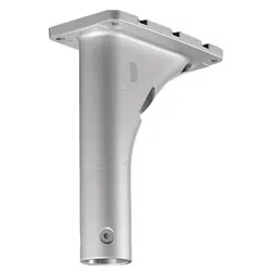
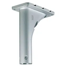
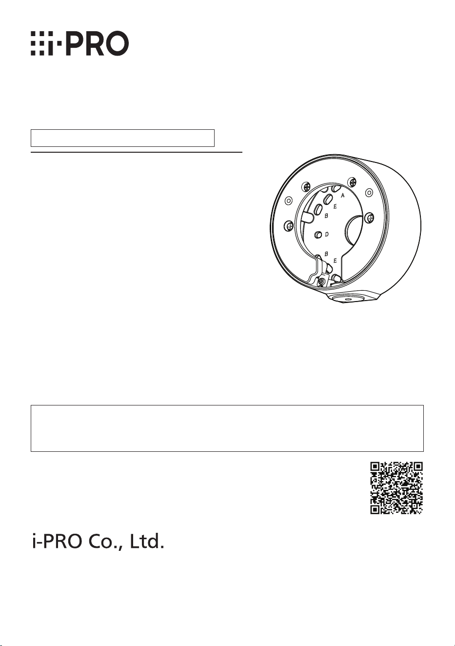
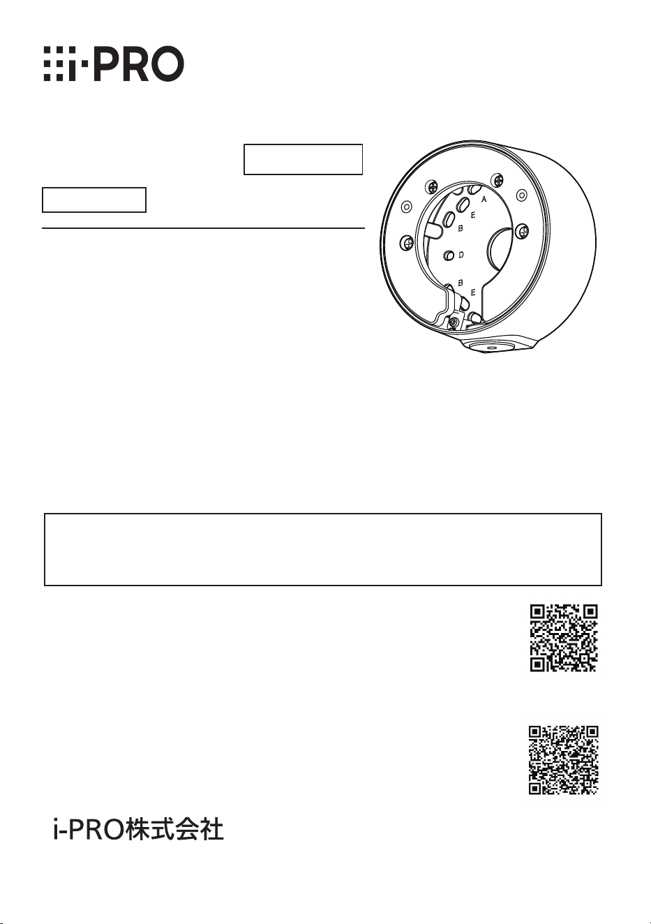
Base Bracket
Model No. WV-QJB502A
Installation Guide
© i-PRO Co., Ltd. 2023
https://www.i-pro.com/
Included Installation Instructions
"<Control No.: C****>" used in these documents should be used to search for
information on our technical information website (https://i-pro.com/products_and_
solutions/en/surveillance/learning-and-support/knowledge-base/technical-information)
and will guide you to the right information.

2
Caution:
• Before attempting to connect or operate
this product, please read these instruc-
tions carefully.
Notice:
• This product is not suitable for use in loca-
tions where children are likely to be pres-
ent.
• Do not install this product in locations
where ordinary persons can easily reach.
• For information about screws and other
parts required for installation, refer to the
corresponding section of this document.
Do not hang down from this product or use this product as a pedestal.
Failure to observe this may cause injury or accidents.
Do not use this bracket except with suitable cameras.
Failure to observe this may cause a drop resulting in injury or accidents.
Refer installation work to the dealer.
Installation work requires technique and experience.
Failure to observe this may cause fire, electric shock, injury, or damage to the product.
Be sure to consult the dealer.
The screws and bolts must be tightened to the specied torque.
Failure to observe this may cause a drop resulting in injury or accidents.
Install the product accurately and securely on the installation surface in
accordance with the installation instructions.
Failure to observe this may cause injury or accidents.
Do not rub the edges of metal parts with your hand.
Failure to observe this may cause injury.
When using this product, also read the “Precautions” described in the operating
instructions for the camera to be attached.
Precautions

3
Preface
Mount the camera onto the ceiling or wall using this bracket.
Use this bracket when conduits are used for wiring, or when there is no space available for
wiring in the ceiling or wall.
The latest information about the supported cameras technical information website.
<Control No.: C0501>
The model number is abbreviated in some descriptions in this manual.
Ambient operating temperature: –50 °C to +60 °C {–58 °F to +140 °F}
Dimensions:
ø127 mm × 56.5 mm (H) {ø5 inches × 2-7/32 inches(H)}
Mass: Approx. 550 g {1.21 lbs}
Finish: Aluminum die cast
<WV-QJB502A-W> <WV-QJB502A-B>
Specifications
In order to prevent injury, this product must be securely mounted to an installation
surface according to Installation Guide of the camera.
Make sure to remove this product if it will no longer be used.
Precautions for installation

4
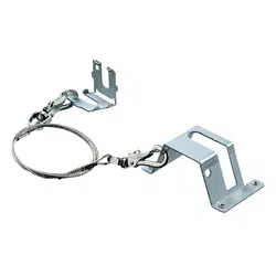
Standard Accessories
Other items that are needed (not included)
Installation method
Recommended
screw*
1
Minimum
pull-out strength*
2
Directly mount the camera onto the installation
surface.
M4 × 16 mm
{5/8 inches}*
3
4 pcs. or 2 pcs.
196 N {44 lbf}
Mount the camera to a two-gangbox/ junction box.
*1
Select screws according to the material of the location that the camera will be mounted
to. In this case, wood screws and nails should not be used.
*2
This value indicates the minimum pull-out strength required value per screw. For infor-
mation about the min-imum pull-out strength, refer to our technical information website
<Control No.: C0120>.
*3
The screw length is an example when installing the camera on a robust installation sur-
face with a thickness of 20 mm {25/32 inches} or more.
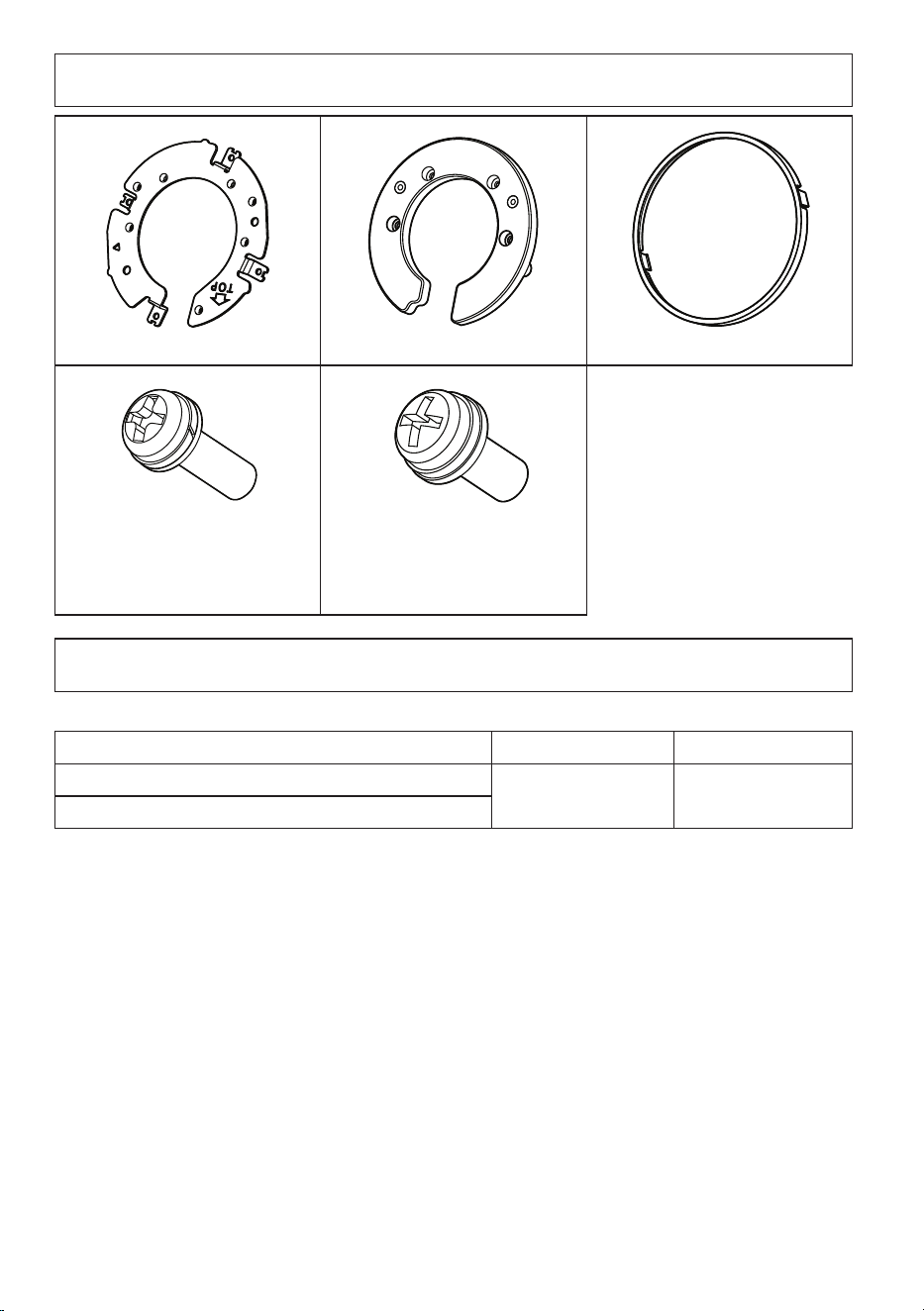
Mounting screws
Attachment plate x1 Cover A x1 Cover B x1
Fixing screw for attachment plate
(M3×10 mm {13/32 inches})
x5
(of them, 1 for spare)
Fixing screw for cover A/
Fixing screw for camera
(M4×10 mm {13/32inches})
x7 (of them, 1 for spare)
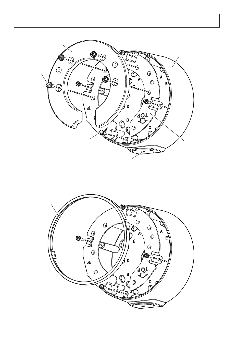
5
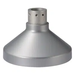
Parts and functions
* The following illustrations explain the case of installing WV-S35xxx series as an example.
Cap for the female thread for the conduit
The female thread for conduit is compliant with ANSI NPSM
(parallel pipe threads) 3/4 or ISO 228-1 (parallel pipe threads) G3/4.
Fixing screw for attachment plate
4 pcs.
Base bracket
Attachment plate
■
<WV-X35xxx Series>/<WV-S35xxx Series>/<WV-S32xxx Series>
■
<WV-U35xxx Series>/<WV-S35xx Series>/<WV-U25x0 Series>/<WV-U21x0 Series>
Cover A
Cover B
Fixing screw
for cover A
4 pcs.

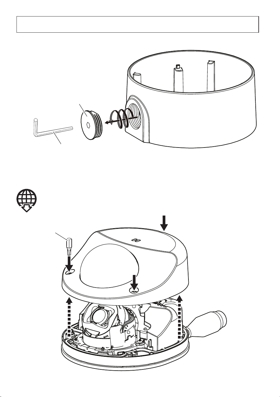
6
Preparations
■
When using the conduit
■
Remove the enclosure from the camera
Cap for the female thread
for the conduit
5 mm {3/16 inches} hexagon wrench
(locally procured)
Refer to the Installation Guide of each camera
Bit (Screw size 6.35 mm {1/4 inches} T10)
(camera accessory)

7
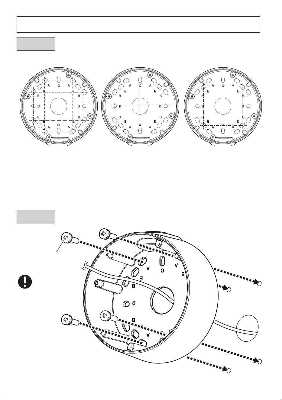
Installation
■
Make a hole on the installation surface
63 mm × 63 mm
{2-15/32 inches
×
2-15/32 inches}
E
83.5 mm*
{3-9/32 inches}
C
D
83.3 mm*
{3-9/32 inches}
83.5 mm × 46 mm
{3-9/32 inches × 1-13/16 inches}
A
B
82.5 mm × 47.6 mm
{3-1/4 inches × 1-7/8 inches}
*
When mounting to a single-gang
junction box, fix it with screws (2
pcs.) (M4: locally procured).
Mounting screw (4 pcs.)
(M4: locally procured)
Minimum
pull-out
strength:
196 N {44 lbf}
(per 1 pc.)
Step 1
Step 2

8
■
Check the image capturing direction of the camera and then determine the
fixing position of the attachment plate.
Left side Downward Right side
The fixing position of the attachment plate can be changed with steps of 90°.
■
Install the attachment plate
Step 3
Recommended
tightening torque:
0.69 N·m {0.51 lbf·ft}
Fixing screw for
attachment plate
(accessory) 4 pcs.
9
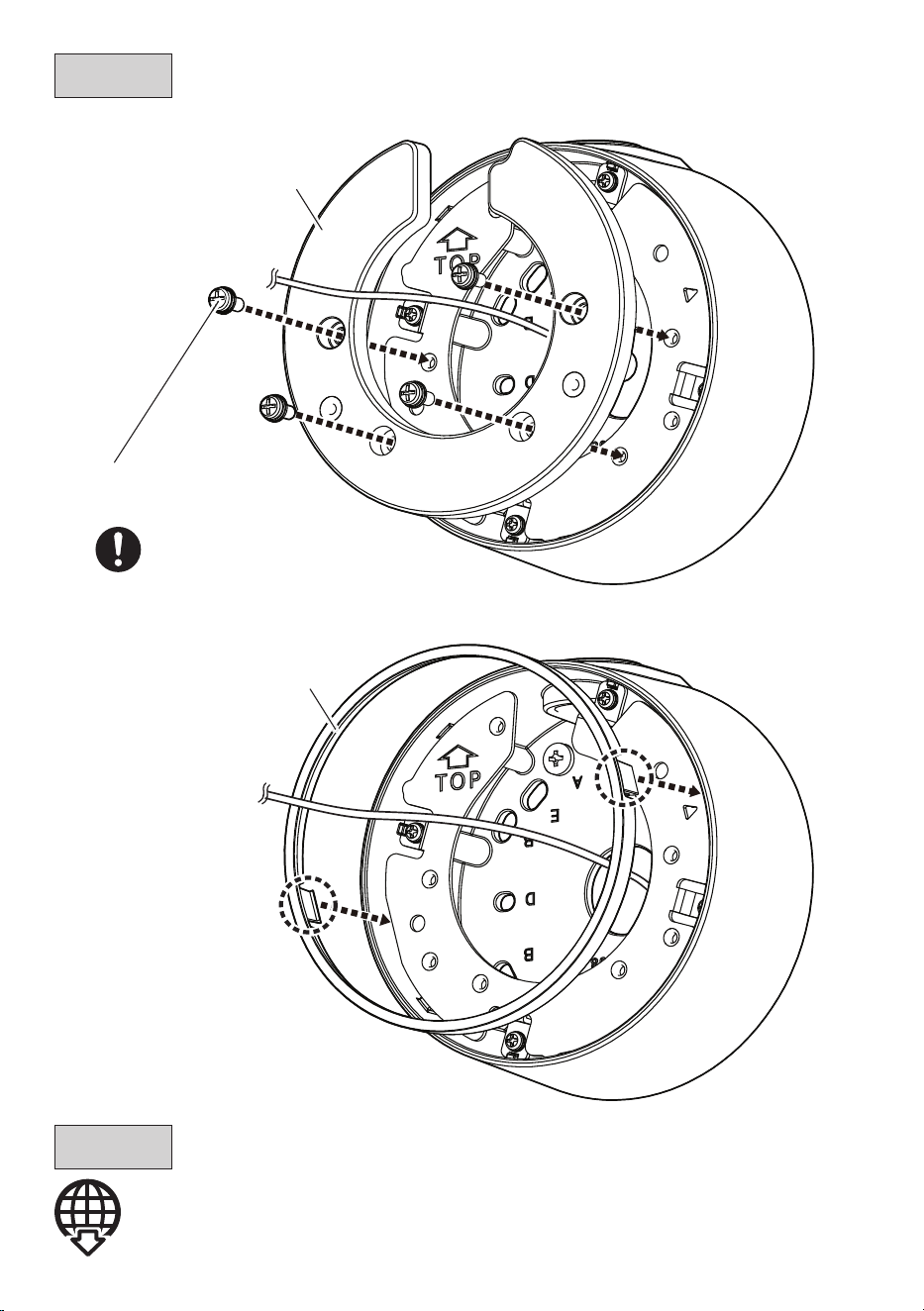
Connect the cable to the camera.
Cover A
Cover B
Refer to the Installation Guide of each camera
Step 4
Step 5
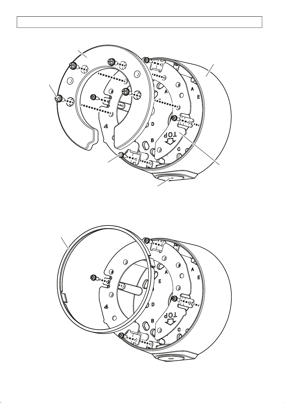
■
<WV-X35xxx Series>/<WV-S35xxx Series>/<WV-S32xxx Series>
■
<WV-U35xxx Series>/<WV-S35xx Series>/<WV-U25x0 Series>/<WV-U21x0 Series>
Recommended tightening torque:
0.69 N·m {0.51 lbf·ft}
Fixing screw for cover A
(accessory) 4 pcs.
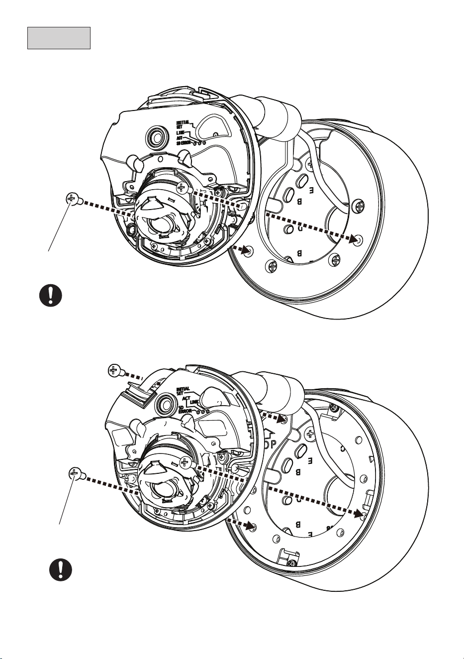
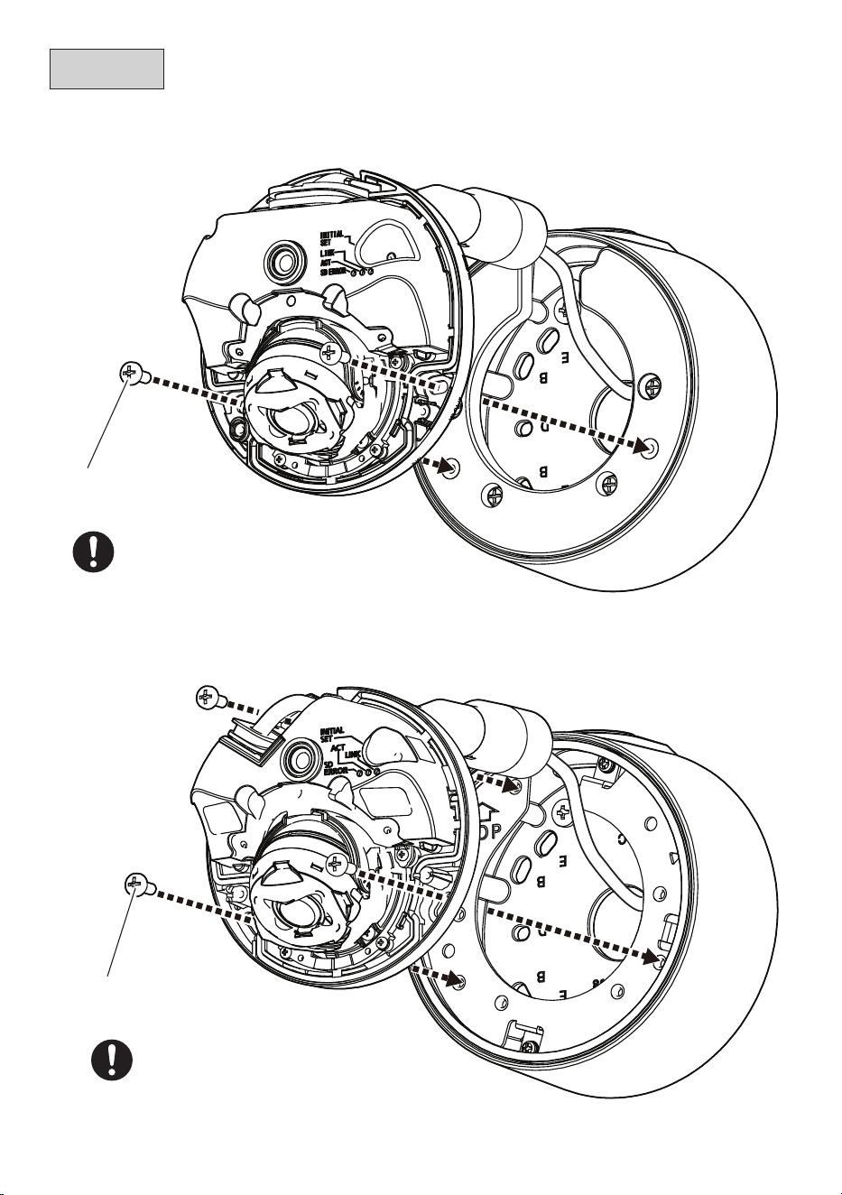
10
Step 6
■
<WV-X35xxx Series>/<WV-S35xxx Series>/<WV-S32xxx Series>
■
<WV-U35xxx Series>
Recommended tightening torque:
1.37 N·m {1.01 lbf·ft}
Fixing screw for camera
(accessory) 3 pcs.
Recommended tightening torque:
1.37 N·m {1.01 lbf·ft}
Fixing screw for camera
(accessory) 2 pcs.
The illustrations explain the case of installing WV-S35xxx series as an example.
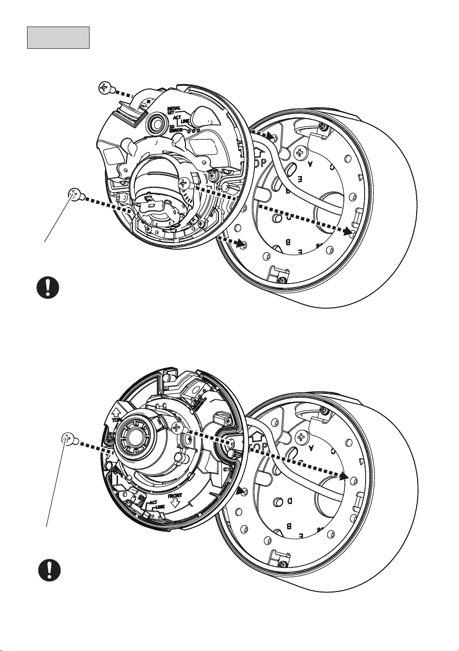
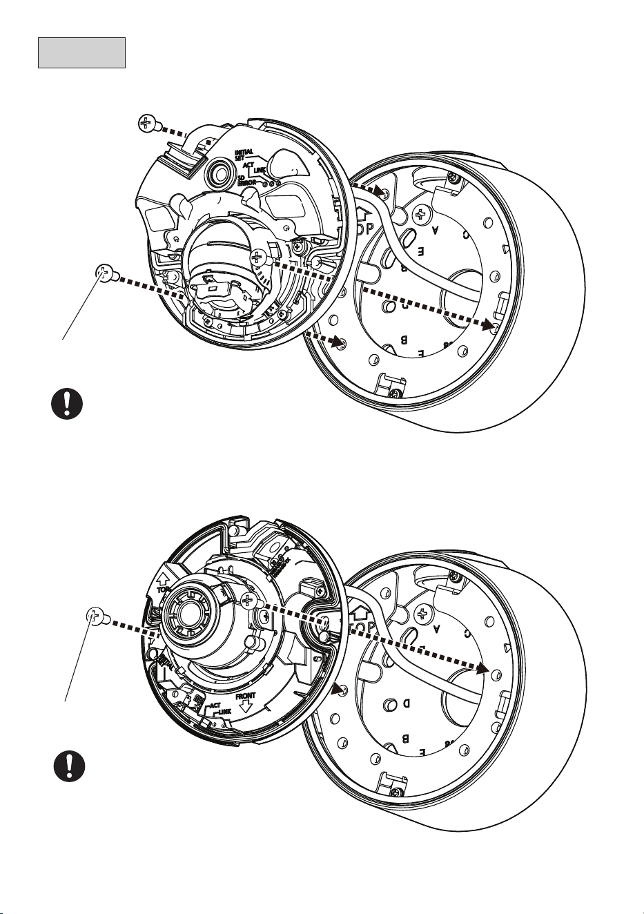
11
(Continued)
■
<WV-S35xx Series>
■
<WV-U25x0 Series>/<WV-U21xx Series>
Fixing screw for camera
(accessory) 3 pcs.
Recommended tightening torque:
1.37 N·m {1.01 lbf·ft}
Step 6
Recommended tightening torque:
1.37 N·m {1.01 lbf·ft}
Fixing screw for camera
(accessory) 2 pcs.

12
Adjust the angle of view of the camera.
Refer to the Installation Guide of each camera
Attach the enclosure.
Refer to the Installation Guide of each camera
Refer to the Installation Guide of the corresponding camera for the recommended tightening torque
to be applied when fixing the enclosure of the camera.
Step 7
Step 8
13
取扱説明書
工事説明付き
ベース金具
品番
WV-QJB502A
このたびは、弊社製品をお買い上げいただき、まことにありがとうございます。
取扱説明書をよくお読みのうえ、正しく安全にお使いください。
ご使用前に「安全上のご注意」を必ずお読みください。
この取扱説明書は大切に保存してください。
製品の改良などにより、ご使用上影響のない範囲で、記載されている外観などが実際の
製品と異なる場合があります。
設置ガイド
取扱説明書に記載されていない方法や、指定の部品を使用しない方法で施工されたこ
とにより事故や損害が生じたときには、当社では責任を負えません。また、その施工
が原因で故障が生じた場合は、製品保証の対象外となります。
i-PRO製品の「お問い合わせ」については、以下の弊社サポートウェブ
サイトを参照してください。
https://i-pro.com/products_and_solutions/ja/surveillance/
contact-us
※「日本エリア」でお使いの場合に限ります。日本以外でお使いの場合の
サービスはいたしかねます。
取扱説明書に記載されている「<管理番号:Cxxxx>」は、以下の弊社技
術情報ウェブサイト内で該当する情報を検索する際に使用する番号です。
https://i-pro.com/products_and_solutions/ja/surveillance/
learning-and-support/knowledge-base/technical-information
i-PRO Co., Ltd. 2022
https://www.i-pro.com/
14
警告
■ ぶら下がらない。足場代わりにしない
(けがや事故の原因となります。)
■ 専用のカメラ以外は取り付けない
(落下によるけがや事故の原因となります)
■ 工事は販売店に依頼する
(工事には技術と経験が必要です。火災、感電、けが、器物損壊の原因となります。)
⇒ 必ず販売店に依頼してください。
■ ねじやボルトは指定されたトルクで締め付ける
(落下によるけがや事故の原因となります。)
■ 設置の説明にしたがって設置面に正しくしっかり取り付ける
(けがや事故の原因となります。)
注意
■ 金属のエッジで手をこすらない
(強くこするとけがの原因となります。)
本金具をご使用の際は、取り付けるカメラの取扱説明書に記載された「安全上のご
注意」とあわせてお読みください。
安全上のご注意
必ずお守りください
■ お守りいただく内容を次の図記号で説明しています。(次は図記号の例です)
人への危害、財産の損害を防止するため、必ずお守りいただくことを説明しています。
■ 誤った使い方をしたときに生じる危害や損害の程度を区分して、説明しています。
してはいけない内容です。
実行しなければならない内容
です。
注意:
取扱説明書をよくお読みのうえ、正しく安全にお使いください。
注記:
本金具は子供がいる可能性のある場所での使用には適していません。
一般の人が容易に触れることができる場所への設置はしないでください。
設置に必要なねじやそのほかの部材などの情報については本書の該当部分を参照してください。
「死亡や重傷を負うおそ
れがある内容」です。
警告
注意
「
軽傷を負うことや、財産の損害が
発生するおそれがある内容」です。

15
商品概要
本金具を使用してカメラを天井または壁に取り付けます。接続管を使用して配線する場合、
または天井裏や壁内部に配線スペースがない場合に本金具を使用します。
取り付け可能なカメラの最新情報 <管理番号:C0501>
本書では、品番の一部を省略している場合があります。
仕様
使用温度範囲 −50 ℃〜+60 ℃
寸法 φ127 mm x 56.5 mm(H)
質量 約550 g
仕上げ アルミダイカスト
<WV-QJB502A-W> <WV-QJB502A-B>
設置上のお願い
■ 設置工事は電気設備技術基準に従って実施してください。
本金具の設置・接続を始める前に必要な周辺機器やケーブルを確認し、準備してください。
接続する前に、カメラ、PCなど接続する機器の電源を切ってください。
■ 傷害防止のため、本金具は、設置の説明に従って設置面にしっかりと取り付け
る必要があります。
■ 本金具を使用しなくなった場合は放置せず、必ず撤去してください。
16
付属品以外に必要なもの
取付方法 推奨ねじ
※1
最低引抜強度
※2
設置面に直接取り付ける M4×16mm
※3
/4本 または 2本
196 N{20 kgf}
2コ 用 スイッチ ボックスを 使って 取り付 ける
※1 ねじの種類は取付場所の材質に合わせて選択してください。木ねじ、くぎは使用しない
でください 。
※2 ねじ1本あたりに要求される最低引抜強度です。最低引抜強度の考え方については技
術情報ウェブサイト<管理番号:C0120>を参照してください。
※3 ねじの長さは厚み20 mm以上の堅牢な設置面に設置する場合の例です。
付属品をご確認ください
アタッチメント金具 x1 カバーA x1 カバーB x1
アタッチメント金具固定ねじ
(M3×10 mm) x5
(うち1本は予備)
カメラ固定用ねじ、
カバーA固定ねじ
(M4×10 mm) x7
(うち1本は予備)
取付ねじ
17
各部の名前
■ <WV-X35xxxシリーズ>/<WV-S35xxxシリーズ>/<WV-S32xxxシリーズ>
■ <WV-U35xxxシリーズ>/<WV-S35xxシリーズ>/<WV-U25x0シリーズ>
/<WV-U21x0シリーズ>
※以降のイラストはS35xxxシリーズを設置する場合を例に説明します。
接続管用めねじキャップ
接続管用めねじは、JIS C 8305(電線管ねじ)のCTG22
またはJIS B 0202(管用平行ねじ)のG3/4に対応しています。
アタッチメント金具固定ねじ x4
カバーA
カバーA
固定ねじ x4
ベース金具
アタッチメント
プレート
カバーB
18
前準備
■ 接続管を使用する場合
■ カメラからエンクロージャーを取り外す。
接続管用めねじキャップ
対辺5mmの六角レンチ
(現地調達)
各カメラの取扱説明書設置編参照
ビット(六角対辺6.35 mm T10)
(カメラ付属品)
19
Step1
設置する
■ 設置面を加工する。
63 mm × 63 mm
E
83.5 mm
※
C
D
83.3 mm
※
83.5 mm × 46 mm
A
B
82.5 mm × 47.6 mm
※ 1コ 用スイッチ ボックスに取り付
ける場合は、取付ねじ2本(M4:
現地調達)で固定してください。
Step2
取付ねじ(4本)
(M4:現地調達)
最低引抜強度:
196 N {20 kgf}
/1本あたり

20
Step3
■ カメラの撮影方向を確認してアタッチメント金具の固定位置を決める。
左向き撮影 下向き撮影 右向き撮影
推奨締付トルク:
0.69 N・m
{7 kgf・cm}
推奨締付トルク:
アタッチメント
金具固定ねじ
( 付 属 品 )4 本
アタッチメント金具の固定位置は90°ごとに変更できます。
■ アタッチメント金具を固定する。

21
Step4
Step5
カメラにケーブルを接続する。
推奨締付トルク:
0.69 N・m
{7 kgf・cm}
カバーA 固定ねじ
( 付 属 品 )4 本
■ <WV-X35xxxシリーズ>/<WV-S35xxxシリーズ>/<WV-S32xxxシリーズ>
■ <WV-U35xxxシリーズ>/<WV-S35xxシリーズ>/<WV-U25x0シリーズ>
/<WV-U21x0シリーズ>
カバーA
カバーB
各カメラの取扱説明書設置編参照
22
Step6
■ <WV-X35xxxシリーズ>/<WV-S35xxxシリーズ>/<WV-S32xxxシリーズ>
■ <WV-U35xxxシリーズ>
推奨締付トルク:
1.37 N・m
{14 kgf・cm}
カメラ固定ねじ
( 付 属 品 )2 本
推奨締付トルク:
1.37 N・m
{14 kgf・cm}
カメラ固定ねじ
( 付 属 品 )3 本
イラストはS35xxxシリーズを設置する場合を例に説明します。
23
Step6
(つづき)
■ <WV-S35xxシリーズ>
■ <WV-U25x0シリーズ>/<WV-U21x0シリーズ>
推奨締付トルク:
1.37 N・m
{14 kgf・cm}
カメラ固定ねじ
( 付 属 品 )3 本
推奨締付トルク:
1.37 N・m
{14 kgf・cm}
カメラ固定ねじ
( 付 属 品 )2 本

24
Step7
カメラの画角を調整する。
各カメラの取扱説明書設置編参照
Step8
エンクロージャーを取り付ける。
各カメラの取扱説明書設置編参照
エンクロージャーを取り付ける際の推奨締め付けトルクについては、各カメラの取扱説明書
設置編を参照してください。