Operating Instructions
Included Installation Instructions
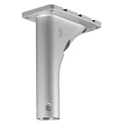
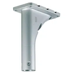
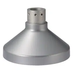
Mount Bracket
Model No. WV-Q124
LOCK
OPEN
© i-PRO Co., Ltd. 2022 Ns1214-3042 PGQX1783WA Printed in China
Before attempting to connect or install this product,
please read these instructions carefully and save this manual for future use.
The model number is abbreviated in some descriptions in this manual.
Specifications
Ambient operating temperature: –40 °C to +50 °C {–40 °F to 122 °F}
Dimensions: Maximum diameter: ø176.0 mm {6-15/16 inches}
Height: 131.0 mm {5-5/32 inches}
Mass:
Main body: Approx. 480 g {1.06 lbs}
Finish:
Main body: Aluminum die cast Silver
Preface
WV-Q124 (mount bracket) is designed to be used to install a fisheye camera or a dome camera for
outdoor use in the following ways.
• When installing on a wall using together with WV-Q122A (wall mount bracket)
Precautions
Refer installation work to the dealer.
Installation work requires technique and experiences. Failure to observe this may cause fire, electric
shock, injury, or damage to the product.
Be sure to consult the dealer.
Periodic inspections shall be conducted.
Rust on the metal parts or screws may cause a fall of the product resulting in injury or accidents.
Consult the dealer for the inspections.
The exclusively designed mount bracket shall be used.
Failure to observe this may cause a drop resulting in injury or accidents.
Use the exclusively designed mount bracket for installation.
The screws and bolts must be tightened to the specified torque.
Failure to observe this may cause a drop resulting in injury or accidents.
Do not install this product in locations subject to vibration.
Loosening of mounting screws or bolts may cause a fall of the product resulting in injury or accidents.
Install this product in a location high enough to avoid people and objects from
bumping the product.
Failure to observe this may cause injury.
The measures of protection against snowfall shall be taken.
Weight of snow may cause a fall of the product resulting in injury or accidents.
Protect the product against snowfall by installing under eaves.
Avoid installing this bracket in the locations where salt damage occurs or corro-
sive gas is produced.
Otherwise, the mounting portions will deteriorate and accidents such as a fall of this product may
occur.
Do not strike or give a strong shock to this product.
Failure to observe this may cause fire or injury.
Do not hang down from this product or use this product as a pedestal.
Failure to observe this may cause injury or accidents.
Do not install the product in a windy place.
Installation of the product in wind with a speed of 60 m/s or more may cause a drop resulting in acci-
dents.
Do not use this bracket except with suitable cameras.
Failure to observe this may cause a drop resulting in injury or accidents.
Do not rub the edges of metal parts with your hand.
Strong rubbing may cause injury.
Precautions for installation
i-PRO Co., Ltd. assumes no responsibility for injuries or property damage resul-
ting from failures arising out of improper installation or operation inconsistent
with this documentation.
Power supply
Use a power supply device equipped with the ON-OFF switch for servicing. When the power cord of
the product is connected to the power supply device, the power will be supplied to the product.
Before cleaning the product, make sure that the power cable is not connected to the main power
supply.
Take notice of humidity.
Install this product when the humidity is low. If this product is installed during rainfall or at a high
humidity, the inside may be exposed to moisture and the dome cover may become foggy.
Mounting method for this product
This product is designed to be used as a pendant mount camera. If the product is mounted on a
desktop or at a slant, it may not work correctly and its lifetime may be shortened.
Do not place this product in the following places:
• Locations where a chemical agent is used such as a swimming pool
• Locations subject to moisture or oil smoke such as a kitchen
• Locations that have a specific environment that is subject to an inflammable atmosphere or sol-
vents
• Locations where radiation, x-ray, intense radio wave, or strong magnetism is produced
• Locations where corrosive gas is produced, locations where it may be damaged by briny air such
as seashores
• Locations where the temperature is not within the specified range (–40 °C to +50 °C {–40 °F to
122 °F})
• Locations subject to condensation as the result of severe changes in temperature
(In case of installing the product in such locations, the dome cover may become foggy or con-
densation may be caused on the cover.)
• Locations subject to vibrations, such as on vehicles, marine vessels, or above product lines
(This product is not designed for on-vehicle use.)
Check before installation
Compatibility of devices is restricted. Before installation, check the ratings and dimensions of the
devices to be used.
Contact your dealer for details.
Screw tightening
• Do not use an impact driver. Use of an impact driver may damage the screws or cause tightening
excessively.
• When a screw is tightened, make the screw at a right angle to the surface. After tightening the
screws or bolts, perform checks to ensure that the tightening is sufficient enough so that there is
no movement or looseness.
Protection against lightning
When cables are used outdoors, there is a chance that they may be affected by lightning. In this
case, install a lightning arrester just before where the cables connect to the camera.
Make sure to remove this product if it will no longer be used.
<Mountable models>
The following cameras for outdoor use can be mounted on WV-Q124.
For the latest information about the mountable models, refer to our support web site
(https://i-pro.com/global/en/surveillance/training_support/support/technical_information).
WV-SW355, WV-SW559, WV-SW458, WV-SFV481
WV-SFV631L, WV-SFV631LT, WV-SFV611L, WV-SFV311
Features
For U.S. and Canada:
i-PRO Americas Inc.
For Europe and other countries:
i-PRO EMEA B.V.
https://www.i-pro.com/
Cover
A Inner cover
B Screw A x3
(Fixing screw for the inner cover: M3 x 8 mm
{5/16 inches})
WV-Q122A
WV-Q124
Camera
Standard accessories
Operating Instructions (this document) ......................................................................................... 1 set
A Inner cover .............................................................................................................................. 1 pc.
B Screw A (Fixing screw for the inner cover: M3 x 8 mm {5/16 inches}) .....4 pcs. (incl. 1 spare screw)
C Base guide plate (For WV-SMR10) ..........................................................................................1 pc.
D Screw B (Fixing screw for the base guide plate: M4 x 8 mm {5/16 inches})
..............................................................................................................5 pcs. (incl. 1 spare screw)
E Screw C (Fixing screw for the network microphone attachment plate: M4 x 8 mm {5/16 inches})
..............................................................................................................5 pcs. (incl. 1 spare screw)
* For installation of WV-Q124 and a camera, the provided accessories of C base guide plate,
D screw B and E screw C are unnecessary.
Required parts other than the above
• Accessories provided with the camera to be installed
Attachment plate ...................................................................................................................1 pc.
Fixing screw for attachment plate (M4 x 8 mm {5/16 inches}) ............................................... 4 pcs.
Major operating controls

Operating Instructions
Included Installation Instructions
Mount Bracket
Model No. WV-Q124
LOCK
OPEN
© i-PRO Co., Ltd. 2022 Ns1214-3042 PGQX1783WA Printed in China
Before attempting to connect or install this product,
please read these instructions carefully and save this manual for future use.
The model number is abbreviated in some descriptions in this manual.
Specifications
Ambient operating temperature: –40 °C to +50 °C {–40 °F to 122 °F}
Dimensions: Maximum diameter: ø176.0 mm {6-15/16 inches}
Height: 131.0 mm {5-5/32 inches}
Mass:
Main body: Approx. 480 g {1.06 lbs}
Finish:
Main body: Aluminum die cast Silver
Preface
WV-Q124 (mount bracket) is designed to be used to install a fisheye camera or a dome camera for
outdoor use in the following ways.
• When installing on a wall using together with WV-Q122A (wall mount bracket)
Precautions
Refer installation work to the dealer.
Installation work requires technique and experiences. Failure to observe this may cause fire, electric
shock, injury, or damage to the product.
Be sure to consult the dealer.
Periodic inspections shall be conducted.
Rust on the metal parts or screws may cause a fall of the product resulting in injury or accidents.
Consult the dealer for the inspections.
The exclusively designed mount bracket shall be used.
Failure to observe this may cause a drop resulting in injury or accidents.
Use the exclusively designed mount bracket for installation.
The screws and bolts must be tightened to the specified torque.
Failure to observe this may cause a drop resulting in injury or accidents.
Do not install this product in locations subject to vibration.
Loosening of mounting screws or bolts may cause a fall of the product resulting in injury or accidents.
Install this product in a location high enough to avoid people and objects from
bumping the product.
Failure to observe this may cause injury.
The measures of protection against snowfall shall be taken.
Weight of snow may cause a fall of the product resulting in injury or accidents.
Protect the product against snowfall by installing under eaves.
Avoid installing this bracket in the locations where salt damage occurs or corro-
sive gas is produced.
Otherwise, the mounting portions will deteriorate and accidents such as a fall of this product may
occur.
Do not strike or give a strong shock to this product.
Failure to observe this may cause fire or injury.
Do not hang down from this product or use this product as a pedestal.
Failure to observe this may cause injury or accidents.
Do not install the product in a windy place.
Installation of the product in wind with a speed of 60 m/s or more may cause a drop resulting in acci-
dents.
Do not use this bracket except with suitable cameras.
Failure to observe this may cause a drop resulting in injury or accidents.
Do not rub the edges of metal parts with your hand.
Strong rubbing may cause injury.
Precautions for installation
i-PRO Co., Ltd. assumes no responsibility for injuries or property damage resul-
ting from failures arising out of improper installation or operation inconsistent
with this documentation.
Power supply
Use a power supply device equipped with the ON-OFF switch for servicing. When the power cord of
the product is connected to the power supply device, the power will be supplied to the product.
Before cleaning the product, make sure that the power cable is not connected to the main power
supply.
Take notice of humidity.
Install this product when the humidity is low. If this product is installed during rainfall or at a high
humidity, the inside may be exposed to moisture and the dome cover may become foggy.
Mounting method for this product
This product is designed to be used as a pendant mount camera. If the product is mounted on a
desktop or at a slant, it may not work correctly and its lifetime may be shortened.
Do not place this product in the following places:
• Locations where a chemical agent is used such as a swimming pool
• Locations subject to moisture or oil smoke such as a kitchen
• Locations that have a specific environment that is subject to an inflammable atmosphere or sol-
vents
• Locations where radiation, x-ray, intense radio wave, or strong magnetism is produced
• Locations where corrosive gas is produced, locations where it may be damaged by briny air such
as seashores
• Locations where the temperature is not within the specified range (–40 °C to +50 °C {–40 °F to
122 °F})
• Locations subject to condensation as the result of severe changes in temperature
(In case of installing the product in such locations, the dome cover may become foggy or con-
densation may be caused on the cover.)
• Locations subject to vibrations, such as on vehicles, marine vessels, or above product lines
(This product is not designed for on-vehicle use.)
Check before installation
Compatibility of devices is restricted. Before installation, check the ratings and dimensions of the
devices to be used.
Contact your dealer for details.
Screw tightening
• Do not use an impact driver. Use of an impact driver may damage the screws or cause tightening
excessively.
• When a screw is tightened, make the screw at a right angle to the surface. After tightening the
screws or bolts, perform checks to ensure that the tightening is sufficient enough so that there is
no movement or looseness.
Protection against lightning
When cables are used outdoors, there is a chance that they may be affected by lightning. In this
case, install a lightning arrester just before where the cables connect to the camera.
Make sure to remove this product if it will no longer be used.
<Mountable models>
The following cameras for outdoor use can be mounted on WV-Q124.
For the latest information about the mountable models, refer to our support web site
(https://i-pro.com/global/en/surveillance/training_support/support/technical_information).
WV-SW355, WV-SW559, WV-SW458, WV-SFV481
WV-SFV631L, WV-SFV631LT, WV-SFV611L, WV-SFV311
Features
For U.S. and Canada:
i-PRO Americas Inc.
For Europe and other countries:
i-PRO EMEA B.V.
https://www.i-pro.com/
Cover
A Inner cover
B Screw A x3
(Fixing screw for the inner cover: M3 x 8 mm
{5/16 inches})
WV-Q122A
WV-Q124
Camera
Standard accessories
Operating Instructions (this document) ......................................................................................... 1 set
A Inner cover .............................................................................................................................. 1 pc.
B Screw A (Fixing screw for the inner cover: M3 x 8 mm {5/16 inches}) .....4 pcs. (incl. 1 spare screw)
C Base guide plate (For WV-SMR10) ..........................................................................................1 pc.
D Screw B (Fixing screw for the base guide plate: M4 x 8 mm {5/16 inches})
..............................................................................................................5 pcs. (incl. 1 spare screw)
E Screw C (Fixing screw for the network microphone attachment plate: M4 x 8 mm {5/16 inches})
..............................................................................................................5 pcs. (incl. 1 spare screw)
* For installation of WV-Q124 and a camera, the provided accessories of C base guide plate,
D screw B and E screw C are unnecessary.
Required parts other than the above
• Accessories provided with the camera to be installed
Attachment plate ...................................................................................................................1 pc.
Fixing screw for attachment plate (M4 x 8 mm {5/16 inches}) ............................................... 4 pcs.
Major operating controls

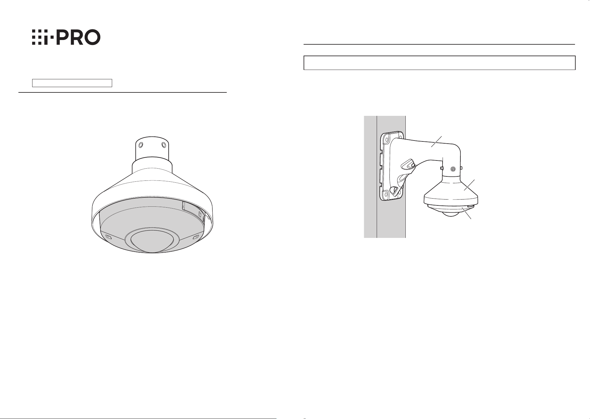
The following are descriptions of how to install on a wall using WV-Q124 (mount bracket) and
WV-Q122A (wall mount bracket).
Installations/Connections
[4] Fix the camera to the attachment plate
w Apply waterproof treatment to the joints of the cables.
Adequate waterproof treatment is required for the cables when installing the camera with cables
exposed. The camera body is waterproof, but the cable ends are not waterproof. Be sure to use
the waterproof tape provided with the camera at the points where the cables are connected and
apply waterproof treatment in the following procedure. Failure to observe this or use of a tape
other than the provided waterproof tape (such as a vinyl tape) may cause water leakage resulting
in malfunction.
Separately apply waterproof treatment to the network cable and other cables as shown in the
illustration below.
IMPORTANT:
• Also waterproof the 2P power cable (provided with the camera), 4P alarm cable (provided
with the camera), and external connections in the same way.
• Stretch the tape by approx. twice (see the illus-
tration at right) and wind it around the cable.
Insufficient tape stretch causes insufficient water-
proofing.
• Waterproof grade (JIS IP66 or equivalent) is
applied to this product only when it is installed
correctly and also an appropriate waterproof
treatment is applied.
The inner side of WV-Q124 (mount bracket) is
not waterproofed.
• When a LAN cable cover is provided with the
camera in the package, attach the LAN cable
cover to the cable as shown in the illustration
and fix it by sliding to the direction indicated by
the arrow. The connector of the LAN cable used
with this camera must meet the following restric-
tions.
[2] Fix the cable with the inner cover of WV-Q124
[3] Attach the attachment plate to the cover part of the WV-Q124
e After connecting the cables to the camera, align the OPEN mark at the side of the camera enclo-
sure to the claw of the attachment plate (provided with the camera). Then, insert the attachment
mounting screws (2 or 3 points) at the bottom of the camera into the holes of the attachment
plate.
After that, move the LOCK mark to the point where the claw of the attachment plate is located by
rotating the camera body clockwise by approx. 15° to fix temporarily.
* Refer to the operating instructions of the connected camera for information on how to mount the
camera.
<For WV-SW458>
Tighten the camera fixing screw located at the enclosure of the camera to fix the attachment plate
and the camera. (Recommended tightening torque: 0.78 N·m {0.58 lbf·ft})
IMPORTANT:
• Enclosure is fixed at the installation auxiliary wire to the camera body, please do not remove the
installation auxiliary wire.
Note:
• As for the enclosure fixing screw, there are three screws models and four screws models
depending on the camera model.
Refer to the operating instructions of the camera for further information.
2. Adjust images from the camera.
* Refer to the operating instructions of the camera for further information on how to adjust.
3. After completing the adjustment, attach the enclosure back to the original position and fix it with
the enclosure fixing screws (3 or 4 screws).
IMPORTANT: This caution shall be applied to all the cameras as described above.
• Be sure to tighten the camera fixing screw. Failure to observe this may cause camera trouble
due to camera falling.
(Recommended tightening torque: 0.78 N·m {0.58 lbf·ft})
* The upper right illustration is provided as an example of attaching the attachment plate for a camera
model having three attachment mounting screws.
<For cameras other than the above>
1. Loosen the fixing screws (3 or 4 screws)
of the enclosure using the bit and remove
the enclosure from the camera body.
Then, fix the camera with the camera fix-
ing screw.
(Recommended tightening torque:
0.78 N·m {0.58 lbf·ft})
q Pass the cables from the wall to the WV-Q122A.
Adjust the length of the cables so that the cables
of approx. 300 mm {11-13/16 inches} come out
from the opening of the WV-Q122A.
Note:
• Do not bundle the cables (Ethernet cable,
power cable, etc.) during installation.
Mounting of A inner cover (accessory) may
become difficult. (The provided illustration
shows the Ethernet cable as a representa-
tive image.)
w Fix the WV-Q122A with M10 screws (locally pro-
cured) or four anchors (locally procured).
Minimum pull-out strength: 823 N {185 lbf}/
per 1 pc.
* Refer to the operating instructions of the mount
bracket (WV-Q122A) for further information on
how to fix.
e Attach the cover part of the WV-Q124 to the
WV-Q122A, and then fix it with M6 hex socket
screws (provided with the wall mount bracket).
(A hex wrench for M6 is required.)
(Recommended tightening torque: 2.45 N·m
{1.81 lbf·ft})
* Fix the cover so that the nameplate of the
WV-Q124 comes in front of the WV-Q122A.
r After fixing the WV-Q124 on the WV-Q122A, lay the cables as shown in the upper right illustration
and confirm that the ends of the cables reach the cable line inside the cover of the WV-Q124.
q Prepare the attachment plate (provided
with the camera) and the fixing screws for
attachment plate (provided with the cam-
era: M4 × 8 mm {5/16 inches}).
w Pass the cables through the attachment
plate.
e Align the “⇧TOP” mark on the attachment
plate with the front of WV-Q122A (wall
mount bracket).
r Fix the attachment plate to the cover part
of the WV-Q124 with the fixing screws for
attachment plate.
(Recommended tightening torque:
0.78 N·m {0.58 lbf·ft})
r Fix the camera to the attachment plate.
Fix the camera and adjust images.
<For WV-SFV481>
1. Loosen two of the sub cover fixing screws
using the bit (provided with the camera) and
remove the sub cover of the camera.
Then, tighten the camera fixing screw to fix the
attachment plate and the camera.
(Recommended tightening torque: 0.78 N·m
{0.58 lbf·ft})
2. Attach the sub cover back to the original posi-
tion and fix with two of the sub cover fixing
screws.
IMPORTANT:
• When using WV-SFV481 or WV-SW458 with a SD memory card, insert the SD memory card to
the camera before mounting the camera onto the WV-Q124.
q Wire the cables as shown below.
Applicable models:
WV-SFV481, WV-SW458, WV-SW559,
WV-SW355, WV-SFV631L, WV-SFV631LT,
WV-SFV611L, WV-SFV311
* WV-SFV481 is used as an example in the
right illustration.
q Connect the cables passed through the
plate in section [3] with the cables from
the camera.
④
②
③
①
②
③
④
* The sub cover is omitted in the illustration.
* The enclosure is omitted in the illustration.
WV-SFV631L is used as an example in the
above illustration.
w Fix A inner cover (accessory) using B screw
A (M3 × 8 mm {5/16 inches}: accessory).
(Recommended tightening torque: 0.78 N·m
{0.58 lbf·ft})
[4] Fix the camera to the attachment plate (continued)
Cable line
Attachment plate
(accessory provided
with the camera)
Cable
Camera
Cables
Nameplate
Cover part of
WV-Q124
Cover part of
WV-Q124
Approx. 300 mm
{11-13/16 inches} from the
opening of WV-Q122A
Fixing screw for
attachment plate x4
(accessory provided with
the camera: M4 x 8 mm
{5/16 inches})
“⇧TOP” mark
A Inner cover
(accessory)
B Screw A (accessory) x3
(Recommended tightening torque: 0.78 N·m {0.58 lbf·ft})
<Example of mounting WV-SFV481>
Claw of the attachment plate
(accessory provided with the camera)
OPEN OPEN
LOCK
Camera
Camera
Camera fixing screw
LOCK
<Example of mounting WV-SFV631L>
Claw of the attachment plate
(accessory provided with the camera)
Camera fixing
screw
<LAN cable> <Alarm input/output cable, power cable, micro-
phone/line input cable, audio output cable>
Wind the tape in ahalf-
overlapping manner.
Wind the tape in a
half-overlapping
manner.
Stretch the tape toapprox.
twice its length.
2x
Max. 16 mm
{5/8 inches}
Max. 14 mm
{9/16 inches}
The hook engages with
the connector terminal
Attachment plate
(accessory provided
with the camera)
Front
direction of
WV-Q122A
(wall mount
bracket)
Nameplate
[1] Fix WV-Q122A (wall mount bracket) on a wall and attach the
cover of WV-Q124 (mount bracket) to the WV-Q122A
1
2
3