
Before attempting to connect or operate this product,
please read these instructions carefully and save this manual for future use.
The model number is abbreviated in some descriptions in this manual.
Operating Instructions
Ceiling Mount Bracket
Model No. WV-Q159C
WV-Q159S

2
CONTENTS
Preface .......................................................................................................................................... 3
Precautions ................................................................................................................................... 3
Precaution for installation .............................................................................................................. 5
Parts and functions ....................................................................................................................... 6
Installations ................................................................................................................................... 7
Specifications .............................................................................................................................. 14
Standard Accessories ................................................................................................................. 14

3
Preface
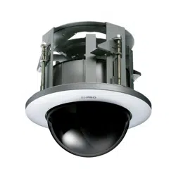
This ceiling mount bracket is exclusively designed to mount the network camera on a ceiling. Refer
to the catalog or the installation guide of the camera for supported cameras.
This bracket can be used for an area with weak pull-out strength such as plasterboard in a double
ceiling.
This bracket is an embedded type to reduce the exposed portion of the camera body.
• WV-Q159C: Clear dome cover
• WV-Q159S: Smoked dome cover (approx. 50 % of transmittance)
Precautions
• Do not hang down from this product or use this product as a pedestal.
Failure to observe this may cause a drop resulting in accidents.
• Use only the specified camera.
Failure to observe this may cause a fall of an inappropriate camera resulting in injury or acci-
dents. Refer to the catalog or the installation guide of the camera for supported cameras
• Avoid installing this bracket in the locations where salt damage occurs or corrosive
gas is produced.
Otherwise, the mounting portions will deteriorate and accidents such as a fall of the camera
may occur.
• Refer installation work to the dealer.
Installation work requires technique and experience. Failure to observe this may cause fire,
electric shock, injury, or damage to the product. Be sure to consult the dealer.
• Do not install this product in locations subject to vibration.
Loosening of mounting screws or bolts may cause a fall of the product resulting in injury or
accidents.
• Install this product in a location high enough to avoid people and objects from bump-
ing the product.
Failure to observe this may cause injury.
• The measures of protection against a fall of the camera shall be taken.
Failure to observe this may cause a drop resulting in injury. Be sure to install this bracket-spe-
cific safety wire.
• The screws and bolts must be tightened to the specified torque.
Failure to observe this may cause a drop resulting in injury or accidents.

4
• Periodic inspections shall be conducted.
Rust on the metal parts or screws may cause a fall of the product resulting in injury. Consult the
dealer for the inspections.
• Select an installation area that can support the total weight.
Selecting an inappropriate installation surface may cause this product to fall down or topple
over, resulting in injury or accidents. Installation work shall be started after sufficient reinforce-
ment.
• Install this product on a
ceiling according to the instructions.
Failure to observe this may cause injury or injury or accidents.
• Do not rub the edges of metal parts with your hand.
Failure to observe this may cause injury.
5
Precaution for installation
In order to prevent injury, the product must be securely mounted to a ceiling according to
Installation Guide.
This product is designed to be used indoors. This product is not oper-
able outdoors.
• Consult the dealer about the installation area to select a strong ceiling area. Make sure that the
installation area is strong enough to hold the total weight of the camera assembly (approx.
1.9kg {4.2 lbs.}) before installation.
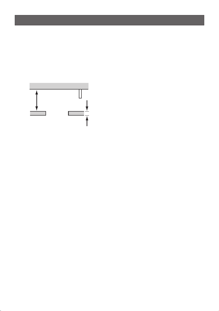
• The installation area shall have 180 mm {7-1/8 inches} or more space behind the ceiling.
180 mm {7-1/8 inches}
or more
Ceiling board: between 9 mm {3/8 inches} and
40 mm {1-9/16 inches}
• The thickness of the ceiling board for installation can range between 9 mm {3/8 inches} and
40mm {1-9/16 inches}.
• Do not place this product in the following places.
• Locations where a chemical agent is used such as a swimming pool
• Locations subject to moisture or oil smoke such as a kitchen
• Locations that have a specific environment that is subject to an inflammable atmosphere or
solvents
• Locations where a radiation, an X-ray, a strong radio wave or a strong magnetic field is gen-
erated
• Locations near coasts directly subjected to sea breezes, or locations subject to corrosive
gases such as from hot springs, volcanic regions, etc.
• Locations where the temperature is not within –10 °C - +50 °C {14 °F - 122 °F}.
• Locations subject to vibrations, such as on vehicles, marine vessels, or above product lines
(This product is not designed for on-vehicle use.)
• Locations where it may get wet from rain or water splash (including under the eaves, etc.)
• Locations subject to moisture or dust
• Locations subject to condensation as the result of severe changes in temperature (In case of
installing the product in such locations, the front cover may become foggy or condensation
may be caused on the cover.)
• The screws and bolts must be tightened with an appropriate tightening torque according to the
material and strength of the installation area. After tightening the screws or bolts, perform visual
check to ensure tightening is enough and there is no backlash.
• The pull-out strength of the installation area shall be 196 N {
44 lbf} or more per 1 screw.
6
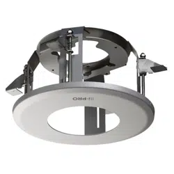
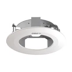
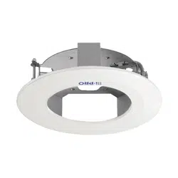
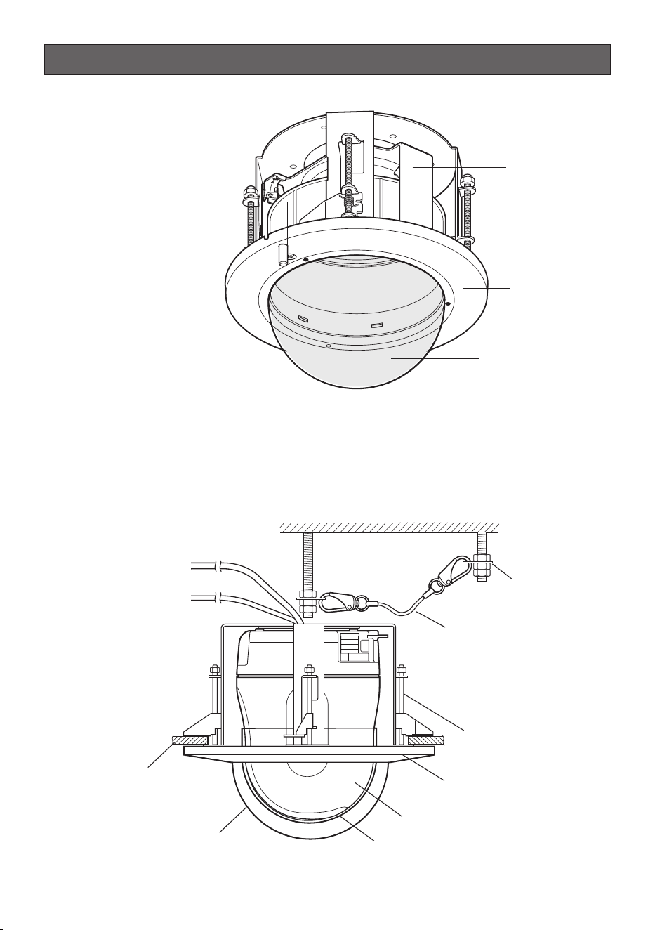
Parts and functions
Decorative cover
Microphone stand*
Fixing screw to be used
for cover fall prevention
Camera mounting
plate
Mounting base
Hole for microphone cable
Dome cover
* If a tiepin type microphone is used, mount the microphone on the rubber-made microphone
stand. Unless the microphone is used, cut the rubber with a nipper or conduct another treat-
ment.
<Installation sample>
Safety wire angle
(Accessory)
Safety wire (Accessory)
Ceiling mount bracket
Decorative cover
Network camera
Dome cover
Ceiling board
Roof space
Inner cover
7
Installations
Be sure to read "Precautions" and "Precaution for installation" before installation. The Installation
Guide of the network camera shall be read as well.
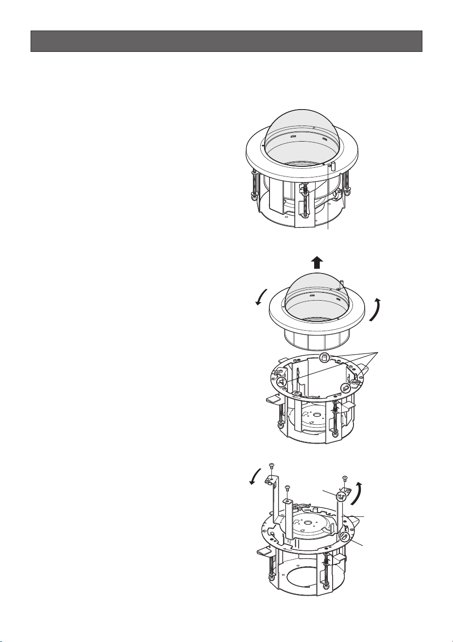
1. Remove the decorative cover.
q Loosen the fixing screw (unremovable)
to be used for cover fall prevention.
w Unhook the decorative cover from the
hooks (3 positions) of the camera
mounting plate and remove the deco-
rative cover by turning it counterclock-
wise.
e Take the inner cover out.
2. Remove the camera mounting plate.
Remove the screws (M4, 3 positions) and
remove the camera mounting plate by
turning it counterclockwise.
Remove the tab of the camera mounting
plate (a) from the hole of the mounting
base (b) (2 positions).
FRONT
LOCK
FRONT
Fixing screw to be used for
cover fall prevention
Hook
FRONT
FRONT
LOCK
(b)
Camera mount-
ing plate
Screw (M4)
(a)
8
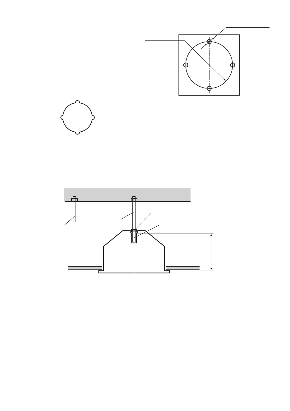
4. Install two anchor bolts (M10 recommended) into the concrete ceiling.
q Determine the anchor bolt length by use of Template B (accessory).
w Position the nut by use of Template B (accessory). (The distance between the bottom sur-
faces of the ceiling board and nut shall be 136 mm {5-3/8 inches}.)
Template B
Ceiling board
Install the anchor bolt in the center of the hole
Determine the anchor bolt length
136 mm {5-3/8 inches}
Use a nut
Anchor bolt for
safety wire
Anchor bolt for
mounting base
Note: If there is already an anchor bolt installed, it can be used as an anchor bolt for the safety
wire. Make sure that the distance between the anchor bolt for the mounting base and the
anchor bolt for the safety wire is 1 m {3.28 feet}or less before use.
3. Put Template A (accessory) against
the ceiling and make a hole.
q Make 4 holes of 12 mm {1/2 inches} in
diameter.
w Remove the center part from the tem-
plate.
e Make a hole of 160 mm {6-5/16
inches} in diameter.
* The hole shape is shown below.
ø12 mm {1/2 inches}
(4 positions)
Ceiling face
ø160 mm
{6-5/16 inches}
Template A
9
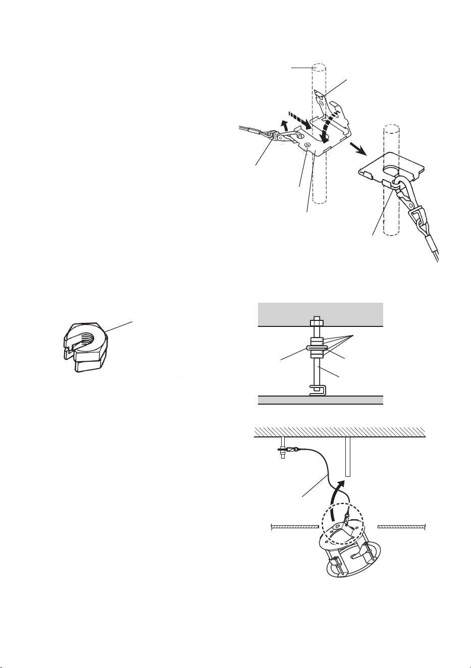
5. Mount the safety wire angle (accessory) on the anchor bolt for the safety wire and
connect the safety wire (accessory) to the angle.
q Disconnect the safety wire from the
safety wire angle.
w Engage the face marked q with the
anchor bolt.
e Bend the face marked w.
r Connect the safety wire to the safety
wire angle again.
Note: To use the anchor bolt that was already installed, the use of 2 spacer nuts is helpful.
Safety wire (Accessory)
Mounting base
Insert the mounting
base into the hole
Roof space
Upper side
Lower
side
Safety wire
w Insert
q Disconnect
e Bend
Mark w
Mark q
Safety wire angle
Anchor bolt
r Connect
Spacer nuts
Safety wire
Spacer nuts
Safety wire angle
Existing anchor bolt
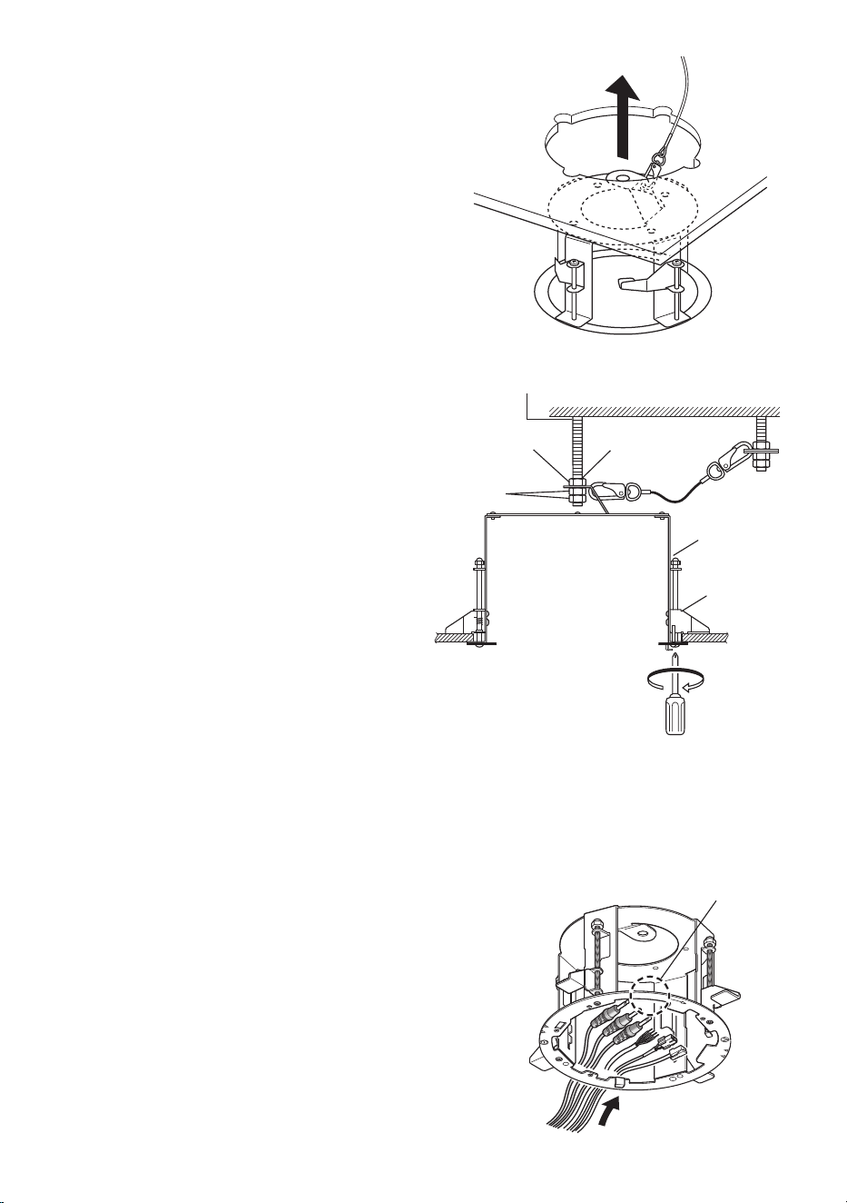
6. Connect the mounting base to another
tip of the safety wire.
10
Ceiling board
fixing screw
Ceiling
board fixing
bracket
Insert the anchor bolt
Nut
Double nuts
Turn clockwise
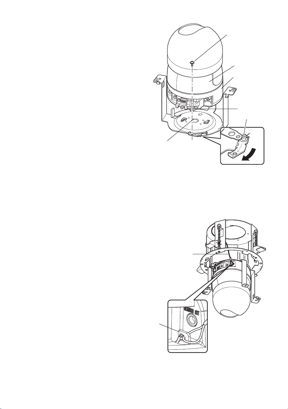
7. Insert the mounting base into the hole
made in Step 3.
8. Secure the mounting base to the ceil-
ing board with the ceiling board fixing
screws (4 positions).
q Engage the top of the mounting base
with the
anchor bolt for the mounting
base
.
w Secure the mounting base by turning
the ceiling board fixing screws clock-
wise.
Turning the ceiling board fixing screws
clockwise provides ceiling board tight-
ening between the bottom of the
mounting base and ceiling board fixing
bracket resulting in mounting base
securing.
(Recommended tigtening torque:
0.78N·m {
0.58 lbf·ft}
e Secure the top of the mounting base
with double nuts.
Important: When securing this bracket on
the ceiling, make sure that the four ceil-
ing board fixing brackets are open as
shown in the figure.
9. Prepare the cables.
Run the cables from the cable inlet.
Important: The cables shall be run from
the opposite side of the mark, FRONT.
Failure to observe this makes the cables
unconnectable since the camera faces
the opposite side.
Anchor bolt for the mounting base
Ceiling board
FRONT
Cable inlet
FRONT
11
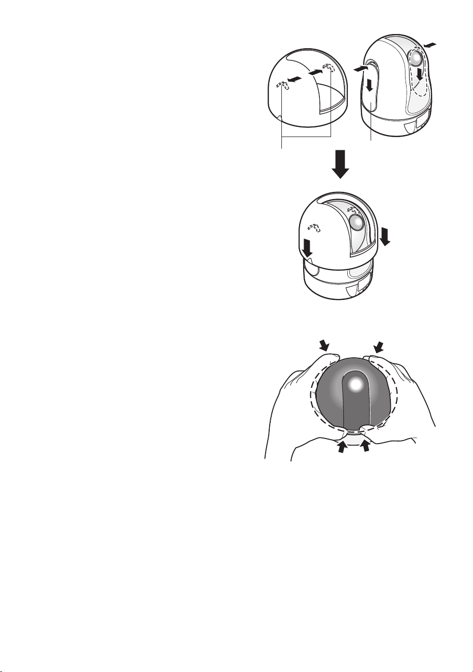
10. Install the inner cover.
Slide the covers located on the both lateral
sides of the camera and put the inner
cover on the camera until the hooks inside
the inner cover are held in the holes of the
camera (until a click is heard).
Important: Put the inner cover down on
the camera until the outside cover of
the camera cannot be seen from the
opening (from which the camera lens is
visible) of the inner cover. If this integra-
tion is not successfully performed, the
inner cover may be removed or the hid-
den part at the top of the screen may
become larger in the WIDE mode.
How to remove the inner cover
Press the inner cover from the front and
rear sides inward (at the same vertical
position as the hooks) to bend the cover
and remove the cover from the camera.
Cover
Hook
Put on until a click is
heard
Press from the front and rear
sides inward to bend
Inner cover
12
FRONT
LOCK
Stationary portion
Center of the
camera mounting
plate
Camera fixing
screw
Lock plate
Guide
Rotating portion
11. Mount the camera on the camera
mounting plate.
q Put the camera onto the camera
mounting plate with aligning the lock
plate of the camera with the guide of
the camera mounting plate and aligning
the center of the camera mounting
plate with the center of the screw for
tripod mounting, and turn the camera
clockwise.
w Secure the camera with 1 piece of the
camera fixing screw (supplied with the
camera).
(Recommended tightening torque:
0.68 N·m {
0.58 lbf·ft})
Important: Be sure to mount the camera
with holding the stationary portion of the
camera. Camera mounting with holding
the rotating portion of the camera may
cause trouble.
12. Connect the safety wire to the camera.
q Connect the safety wire locked on the
mounting base to the camera.
Make sure that the apical ring of the
safety wire is engaged with the safety
wire hook of the camera by pulling the
safety wire after connection.
13. Connect the cables to the camera.
FRONT
FRONT
LOCK
Mounting base
Safety wire
Safety wire hook
13
START
END
FRONT
FRONT
LOCK
Mounting base
Camera mounting plate
Align A with A
Align B with B
FRONT
LOCK
FRONT
FRONT
LOCK
FRONT
Projections
Hooks for the
decorative cover
*1 position on the
rear side
Fixing screw to be used for cover fall prevention
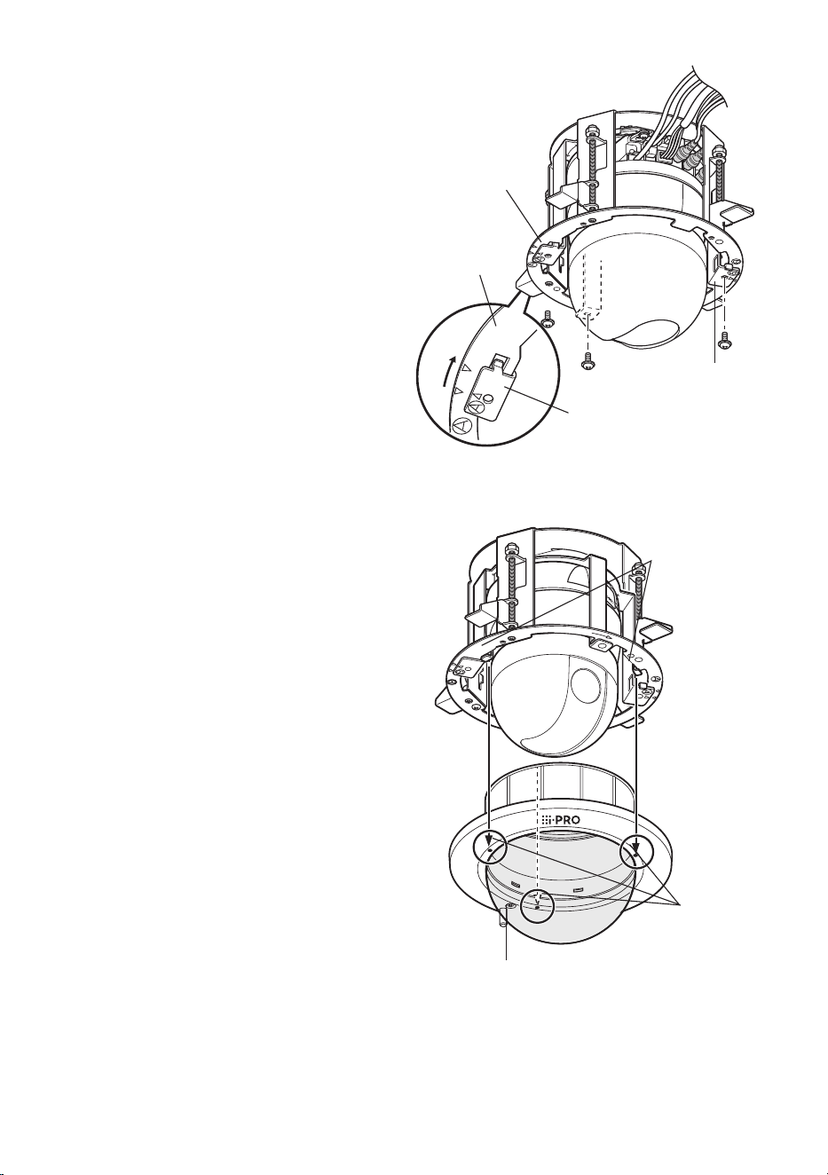
14. Mount the camera mounting plate on
the mounting base.
q Align the marks (A to A and B to B)
between the camera mounting plate
and mounting base.
w Mount the camera mounting plate on
the mounting base with aligning g of
the camera mounting plate with
"STARTh" of the mounting base.
e Turn the camera mounting plate until g
of the camera mounting base aligns
with "ENDh" of the mounting base.
r Tighten the 3 screws that were
removed in Step 2.
(Recommended tightening torque:
1.6 N·m {
1.18 lbf·ft})
Important: Do not let the cables be caught
during installation work.
15. Mount the decorative cover.
q Mount the decorative cover on the
camera mounting plate with engaging
the projections of the decorative cover
with the hooks for the decorative cover.
w Turn the decorative cover clockwise
while pressing the projections upward
and the cover is locked.
Important: The mark, "FRONT", shall be
aligned with the i-PRO logo.
16. Tighten the fixing screw to be used for
cover fall prevention.
(Recommended tightening torque:
1.6 N·m {
1.18 lbf·ft})
17. Remove the protection sheet from the
dome cover.
Remove the cover film from the dome
cover after the installation is completed.
Note: When the camera lens is pointed in
the horizontal direction, the inner cover
interferes with the camera's view, and
consequently about upper half of the
monitor screen is hidden in the WIDE
mode.

14
Specifications
Ambient temperature: –10 °C to + 50 °C {14 °F to 122 °F}
Dimensions: ø190 mm x 212 mm (H)
{ø7-15/32 inches x 8-11/32 inches (H)}
Mass: Approx. 800 g {1.77 lbs.}
Finish: Main body : Treatment steel
Decorative cover : ABS resin with silver metallic coating
Dome cover :
PMMA resin Clear WV-Q159C
Smoke WV-Q159S
Standard Accessories
Operating Instructions (this book) ............................... 1 pc.
The following are for installation
Safety wire .................................................................. 1 pc.
Safety wire angle ........................................................ 1 pc.
Template A ................................................................. 1 sheet
Template B ................................................................. 1 sheet
Inner cover ................................................................. 1 pc.

15

For U.S. and Canada:
i-PRO Americas Inc.
For Europe and other countries:
i-PRO EMEA B.V.
https://www.i-pro.com/
Ns0817-2042 PGQX2210XA Printed in China
© i-PRO Co., Ltd. 2022