Preface
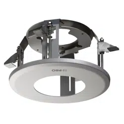
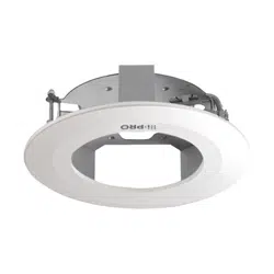
This ceiling mount bracket is exclusively designed to mount the camera on a ceiling. This bracket
can be used for an area with weak pull-out strength such as plasterboard in a double ceiling. For the
latest information about the supported cameras, refer to our support website
(https://i-pro.com/global/en/surveillance/training_support/support/technical_information<Control No.:
C0501>).
Specifications
Ambient operating temperature: –50 °C to +60 °C {–58 °F to +140 °F}
Dimensions: ø186mm × 76.2mm (H)* {ø7-5/16 inches × 3 inches}
*Including decorative cover thickness: 15.7mm {5/8 inches}
Mass: Approx. 350 g {0.77 lbs}
Finish: Main body: Surface treatment steel sheet
Decorative cover: ABS resin i-PRO white
Precautions for installation
In order to prevent injury, the product must be securely mounted to a ceiling according to
the Installation Guide of this bracket.
Installation area for this product
• Make sure that the installation area is strong enough
to hold the total weight of the camera assembly
before installation.
• The installation area shall have 70mm {2-3/4 inches}
or more space behind the ceiling board.
• The thickness of the ceiling board for installation can
range between 9mm {11/32 inches} and 30mm
{1-3/16 inches}.
Ceiling board: between 9 mm {11/32 inches}
and 30 mm {1-3/16 inches}
70 mm {2-3/4 inches}
or more
Make sure to remove this product if it will no longer be used.
When using the IR LED built into the camera to view images in a dark area
If the direction is adjusted towards the surface where the camera is installed (a ceiling), reflections
from the decorative cover or installation surface (ceiling) may cause all or a part of the image to
appear washed out. Adjust the tilt so that there are no reflections in the images.
Installation surface (ceiling)
Decorative
cover
Reflections may occur in the
range of approx. 20°.
Reflections are less likely to occur.
* The dome cover is omitted for ease of explanation.
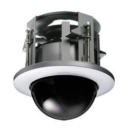
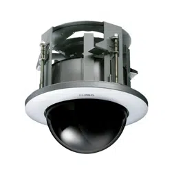
Parts and functions
Triangle mark
(top / bottom)*
Clamp plate
Clamping screw Spring hook Main body
Clamp plateSpring hookDecorative cover
Clamping screw
* Because the triangle mark is engraved on the bracket, it can be seen from both the top and bottom
sides.
Standard accessories
Operating Instructions (this document) ......... 1 pc.
Template (for tracing the hole shape) ....... 1 sheet
Fixing screw (M4 x 8 mm) .......................... 5 pcs.
(of them, 1 for spare)
Decorative cover .......................................... 1 pc.
AF button push tool ..................................... 1 pc.
© i-PRO Co., Ltd. 2022
Cs0520-1042
Printed in China
For U.S. and Canada:
i-PRO Americas Inc.
For Europe and other countries:
i-PRO EMEA B.V.
https://www.i-pro.com/
Caution:
• Before attempting to connect or operate
this product, please read these instructions
carefully.
Notice:
• This product is not suitable for use in
locations where children are likely to be
present.
• Do not install this product in locations where
ordinary persons can easily reach.
• For information about screws and brackets
required for installation, refer to the
corresponding section of this document.
Precautions
Do not use this bracket except with suitable cameras.
Failure to observe this may cause a drop resulting in injury or accidents.
Refer installation work to the dealer.
Installation work requires technique and experience. Failure to observe this may cause fire, electric
shock, injury, or damage to the product.
Be sure to consult the dealer.
Install the product securely on a ceiling in accordance with the installation
instructions.
Failure to observe this may cause injury or accidents.
Do not rub the edges of metal parts with your hand.
Failure to observe this may cause injury.
When using this product, also read the “Precautions” described in the
operating instructions for the camera to be attached.
Operating Instructions
Included Installation Instructions
Ceiling Mount Bracket
Model No.
WV-QEM100-W
• Before attempting to connect or install this product, please read these instructions carefully and
save this manual for future use.
• The external appearance and other parts shown in this manual may differ from the actual
product within the scope that will not interfere with normal use due to improvement of the
product.
i-PRO Co., Ltd. assumes no responsibility for injuries or property damage resulting
from failures arising out of improper installation or operation inconsistent with this
documentation.
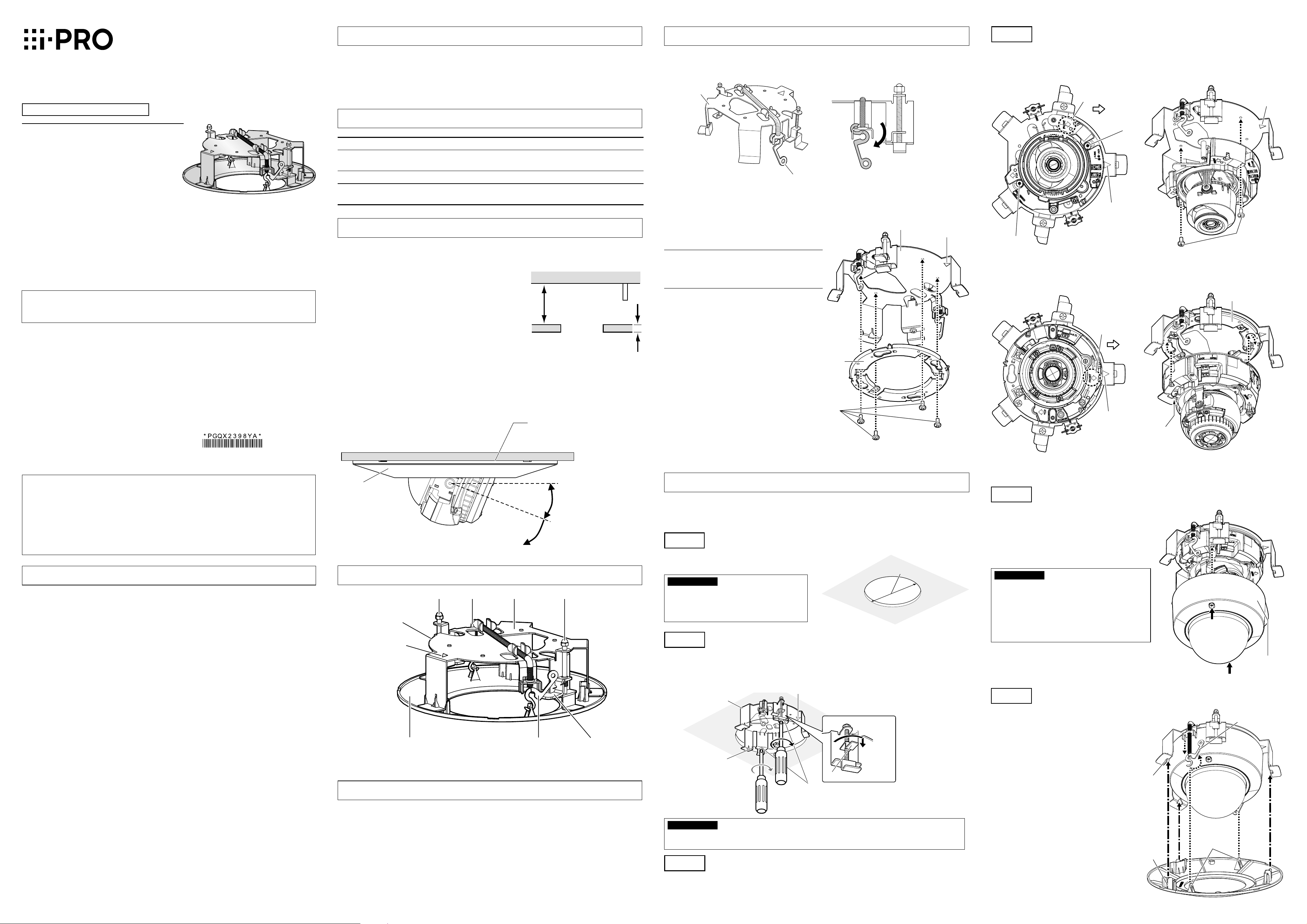
Preparations
Position 2 of the spring hooks of the main body as shown in the illustration below.
When the ceiling mount bracket is installed after positioning them in the opposite side, they may
become hard to pull out.
Main body
Spring hook
Move the hook head downward.
Fix the attachment plate (camera accessory) to the ceiling mount bracket.
Attach the attachment plate (camera accessory) to the ceiling mount bracket first if they are needed
for the attachment of the camera body.
< When securing the camera body using the
attachment plate>
Main body
Triangle mark
Attachment plate
(camera accessory)
Fixing screws
(M4 x 8 mm: accessory)
Recommended
tightening torque:
1.6 N·m {1.18 lbf·ft}
Note
:
• When using a camera type that directly
attaches to installation surfaces, this
preparation is not required.
Step4
Fix the camera body to the ceiling mount bracket.
The triangle mark of the ceiling mount bracket and the direction marker (FRONT
) of the camera
body should be located on the same sides.
<When directly attaching to the ceiling
mount bracket>
Fixing screws (M4 x 8 mm: accessory)
Recommended tightening torque: 1.6 N·m {1.18 lbf·ft}
Camera FRONT
direction
Attaching screw
position
Triangle mark
Attaching
screw position
Triangle mark
Fixing screws
(M4 x 8 mm
: accessory)
<When using the attachment plate>
Align the attachment fixing screws on the bottom side of the camera with the holes of the
attachment plate, and temporarily attach the camera by rotating it about 15° clockwise. Next,
secure the camera with the camera fixing screw.
Camera FRONT
direction
Triangle mark
Attachment plate
Camera fixing screw (Red)
Recommended tightening
torque: 0.78 N·m {0.58 lbf·ft}
From here on explanations use illustrations for <When using the attachment plate>.
Step5
Adjust the angle of view of the camera and attach the enclosure.
Adjust the PAN, TILT, etc. of the camera, and then
adjust the angle of view. When the adjustment is
completed, attach the enclosure to the camera.
• If the AF (Auto Focus) button on the side of the
camera body must be pressed after installing the
camera, use the AF button push tool (accessory).
Enclosure
IMPORTANT
:
• After complete installation, remove the
protection film from the dome cover.
• Attaching the enclosure may cause slight
defocusing. In this case, execute the auto focus
function from the setup menu.
•
If there are fingerprints or dirt on the dome cover,
wipe the dome cover with a soft, dry cloth.
Step6
Attach the decorative cover.
Align the bracket with the 3 guides of the
decorative cover, pull out both the spring hooks
and attach the hooks to the decorative cover.
Make sure that the cover is attached to the
ceiling with no space between them.
* Match the “i-PRO” logos on the cover and on
the camera.
Guides of the
decorative cover
(3 places)
Decorative
cover
connection
parts
Fixing holes
(3 places)
Spring hooks
(2 places)
Installations
Be sure to read “Precautions” and “Precautions for installation” before installation.
Refer to the operating instructions of the camera for details on the camera installation (including the
camera mounting, cable connection and adjustment).
Step1
Make a hole of 160 mm {6-5/16 inches} diameter using a specialized
tool, etc.
Make a mounting hole in the ceiling using the
template (accessory).
Ceiling
ø160 mm
{6-5/16 inches}
IMPORTANT
:
• Make a hole precisely. When the opened
hole is bigger or deformed too much, the
ceiling mount bracket cannot be stuck on
the ceiling board securely.
Step2
Fix the ceiling mount bracket onto the ceiling board.
Loosen the fixing screws by rotating them counterclockwise until the length between the clamp plates
becomes wider than the thickness of the ceiling board. Insert the ceiling mount bracket into the
ceiling board, and clamp and secure the ceiling board by rotating the fixing screws clockwise.
Main body
The thickness of the
ceiling board is between
9 mm {11/32 inches}
and 30 mm {1-3/16 inches}
for installation.
Fixing screws (accessory)
Recommended tightening torque:
1.6 N·m {1.18 lbf·ft}
Triangle mark
Clamp plates
Clamp
the ceiling
board.
* The “i-PRO” logo on the camera and the
decorative cover should be located on the
side of this triangle mark.
IMPORTANT
:
• When the ceiling board is plasterboard, make sure that no crack was made on the ceiling board
by clamping.
Step3
Connect the cables to the camera.
Remove the enclosure from the camera body and connect the cables from above the ceiling board
first.