Loading ...
Loading ...
Loading ...
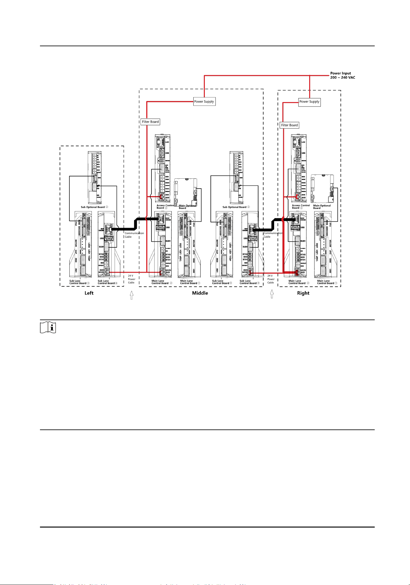
Figure 4-3 General Wiring
Note
●
The power cable from power supply to the main lane control board has been connected. You will
need to prepare the 14 AWG power cable to connect the AC power input to power supply.
●
The supplied 2 interconnecng cables need connecng on-site:
1. 24 V power cable of 14 AWG. The cable is 4 m in length and put inside the right and middle
pedestal at the exit.
2. CAT5e
Communicaon cable. The cable is 4 m in length and put inside the package of the
right/middle pedestal.
●
The ① and ② or ③ and ④ refer to the two sides of a same board.
●
Barrier opens at the entrance/exit: connect to BTN1/BTN2 and GND.
4.3.2 Main Lane Control Board Terminal Descripon
The main lane control board contains interconnecng interface, USB ash drive interface
(reserved), access control board interface, re input interface, exit buon interface, 12 VDC output
interface (reserved), 24 VDC input interface, fan interface, communicaon interface, encoder
DS-K3Y220(L)X Series Flap Barrier User Manual
12
Loading ...
Loading ...
Loading ...