Loading ...
Loading ...
Loading ...
MDO-2000E series User Manual
198
Logic Analyzer Operation
Overview
Background
The logic analyzer inputs can be used to measure
discrete inputs or can be used to measure values
on a parallel or serial bus.
The logic analyzer has a sample rate of 1GSa/s
with a bandwidth of 200MHz.
Supported Logic
Thresholds
TTL, CMOS,
ECL, PELC,
User- defined
The MDO-2000E supports
common logic thresholds and
supports user-defined thresholds
of ± 5V if the in-built threshold
levels are unsuitable.
Digital Trigger
Types
Edge, Pulse
Width, Timeout,
Bus, Logic
As standard, the digital channels
support basic edge, pulse width,
timeout as well as bus and logic
triggers.
Using the Logic Analyzer Probes
Background
This section will describe how to connect the
digital channels to the device under test.
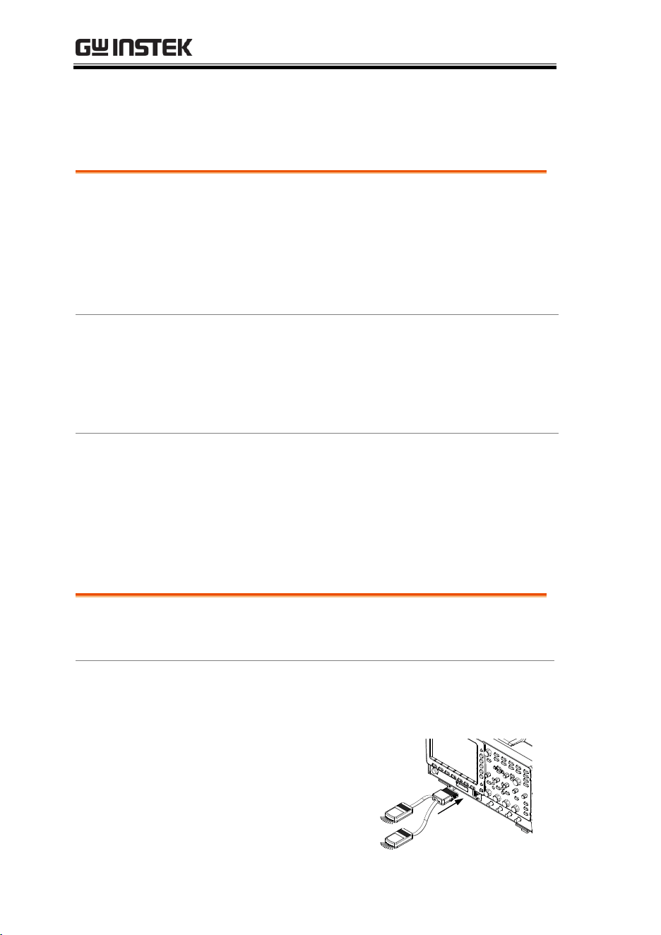
Connection
1. Turn the DUT off to protect it from being short
circuited when the probes are attached.
2. Insert the Logic
Analyzer probe
(GTL-16E) into the
Logic Analyzer slot
input.
Loading ...
Loading ...
Loading ...