Loading ...
Loading ...
Loading ...
1662/1663/1664 FC
Users Manual
54
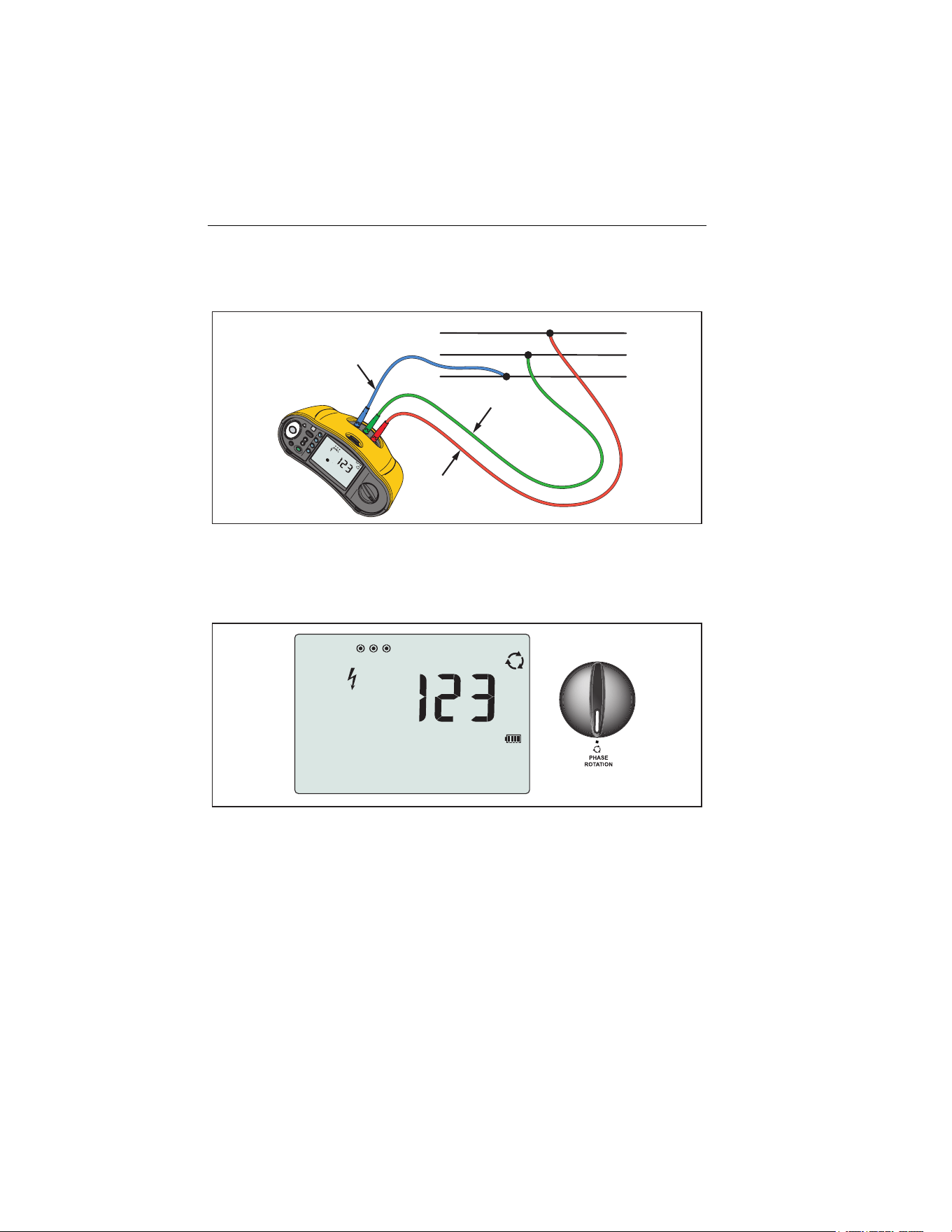
Phase Rotation Tests
Use the connection shown in Figure 10 for a phase rotation test connection.
B
G
R
L1
L2
L3
PE (L2/Green)
L (L1/Red)
N (L3/Blue)
hwl022.eps
Figure 10. Phase Rotation Test Connection
To do a phase rotation test:
1. Turn the rotary dial to the position. See Figure 11.
hwl011.eps
Figure 11. Phase Rotation Display
2. The primary display shows:
• 123 for correct phase rotation.
• 321 for reversed phase rotation.
• Dashes (---) when insufficient voltage is sensed.
1.888.610.7664 sales@GlobalTestSupply.com
Fluke-Direct.com
Loading ...
Loading ...
Loading ...