Loading ...
Loading ...
Loading ...
1662/1663/1664 FC
Users Manual
42
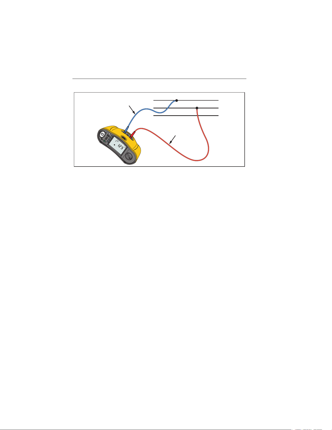
L1
L2
L3
B
R
L (L1/Red)
N (L3/Blue)
hwl025.eps
Figure 7. 3-Phase System Measurement
RCD Tripping Time Measurements
In this test, a calibrated fault current is induced into the circuit to cause the RCD
to trip. The meter measures and shows the time required for the RCD to trip.
You can do this test with test leads or the mains cord. The test is done with a
live circuit.
You can use the Tester to do the RCD tripping time test in Auto Start, which
makes it easier for one person to do the test. If the RCD has a special nominal
current setting other than the standard options, 10, 30, 100, 300, and 500, or
1000 mA, you can use a custom setting with the Var mode.
Note
When you make trip time measurements for any type of RCD,
the Tester first determines if the actual test will cause a fault
voltage exceeding the limit (25 V or 50 V). If yes, shows
on the display.
To avoid having an inaccurate trip time for S type (time delay)
RCDs, a 30 second delay is activated between the pretest and
the actual test. This RCD type needs a delay because it
contains RC circuits that are required to settle before applying
the full test.
1.888.610.7664 sales@GlobalTestSupply.com
Fluke-Direct.com
Loading ...
Loading ...
Loading ...