0
PREMIUM CURVE MANUAL TREADMILL
SF-X7100
USER MANUAL
IMPORTANT! Please retain owner’s manual for maintenance and adjustment instructions. Your
satisfaction is very important to us, PLEASE DO NOT RETURN UNTIL YOU HAVE
CONTACTED US: [email protected] or 1-877-90SUNNY (877-907-8669).

1
IMPORTANT SAFETY INSTRUCTIONS
We thank you for choosing our product. To ensure your safety and health, please use this equipment
correctly. It is important to read this entire manual before assembling and using the equipment. Safe
and effective use can only be achieved if the equipment is assembled, maintained, and used properly.
It is your responsibility to ensure that all users of the equipment are informed of all warnings and
precautions.
1. Before starting any exercise program, you should consult your physician to determine if you have
any medical or physical condition that could put your health and safety at risk or prevent you from
using the equipment properly. Your physician’s advice is essential if you are taking medication that
affects your heart rate, blood pressure or cholesterol level.
2. Be aware of your body’s signals. Incorrect or excessive exercise can damage your health. Stop
exercising if you experience any of the following symptoms: pain, tightness in your chest, irregular
heartbeat, shortness of breath, lightheadedness, dizziness, or feelings of nausea. If you do
experience any of these conditions, you should consult your physician before continuing with your
exercise program.
3. Keep children and pets away from the equipment. The equipment is designed for adult use only.
4. Use the equipment on a solid, flat level surface with a protective cover for your floor or carpet. To
ensure safety, the equipment should have at least 8 feet (240 cm) of free space behind it and 2
feet (60 cm) on each side. Do not place the treadmill on any surface that blocks air openings. To
protect the floor or carpet from damage, place a mat under the treadmill.
5. Ensure that all nuts and bolts are securely tightened before using the equipment. The safety of the
equipment can only be maintained if it is regularly examined for damage and/or wear and tear.
6. Always use the equipment as indicated. If you find any defective components while assembling or
checking the equipment, or if you hear any unusual noises coming from the equipment during
exercise, discontinue use of the equipment immediately and do not use until the problem has
been rectified.
7. Wear suitable clothing while using the equipment. Avoid wearing loose clothing that may become
entangled in the equipment.
8. Do not place fingers or objects into the moving parts of the equipment.
9. The maximum weight capacity of this unit is 375 lbs (170 kgs).
10. The equipment is not suitable for therapeutic use.
11. To avoid bodily injury and/or damage to the product or property, proper lifting and moving are
required.
12. Your product is intended for use in cool, dry conditions. You should avoid storage in extremely
cold, hot, or damp areas as this may lead to corrosion and other related problems.
13. This equipment is designed for indoor and home use only, it is not intended for commercial use!
2
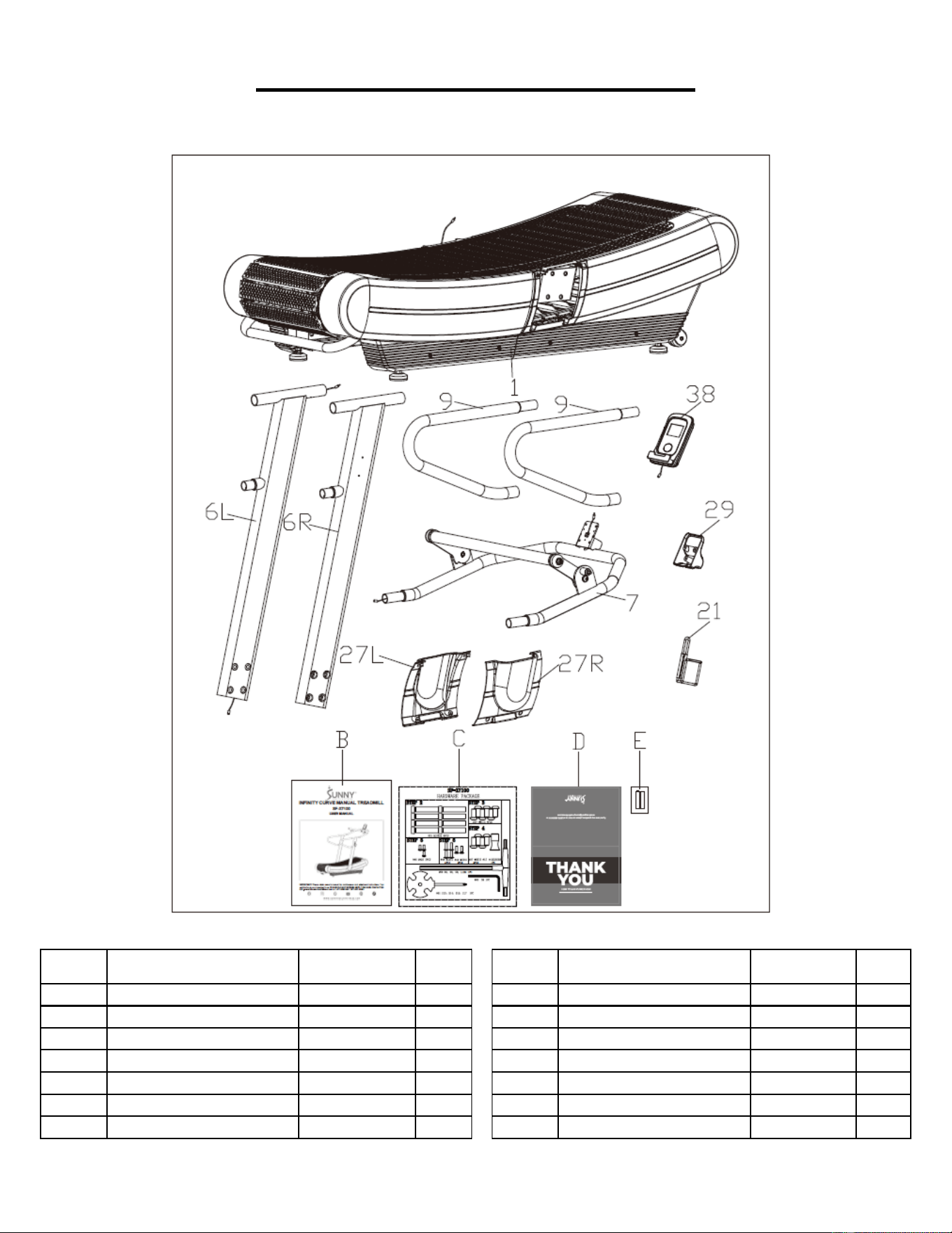
PRE-ASSEMBLY CHECK LIST
Before you start to assemble, please make sure all parts are included.
No.
Description
Spec.
Qty.
No.
Description
Spec.
Qty.
1
Main Frame
1
27R
Right Upright Tube
Cover
1
6L
Left Upright Tube
1
29
Meter Cover
1
6R
Right Upright Tube
1
38
Meter
BJHT038B
1
7
Handlebar Support
1
B
Manual
1
9
Handrail
2
C
Hardware Package
1
21
Bottle Holder
1
D
Thank You Card
1
27L
Left Upright Tube Cover
1
E
Battery
AAA
2
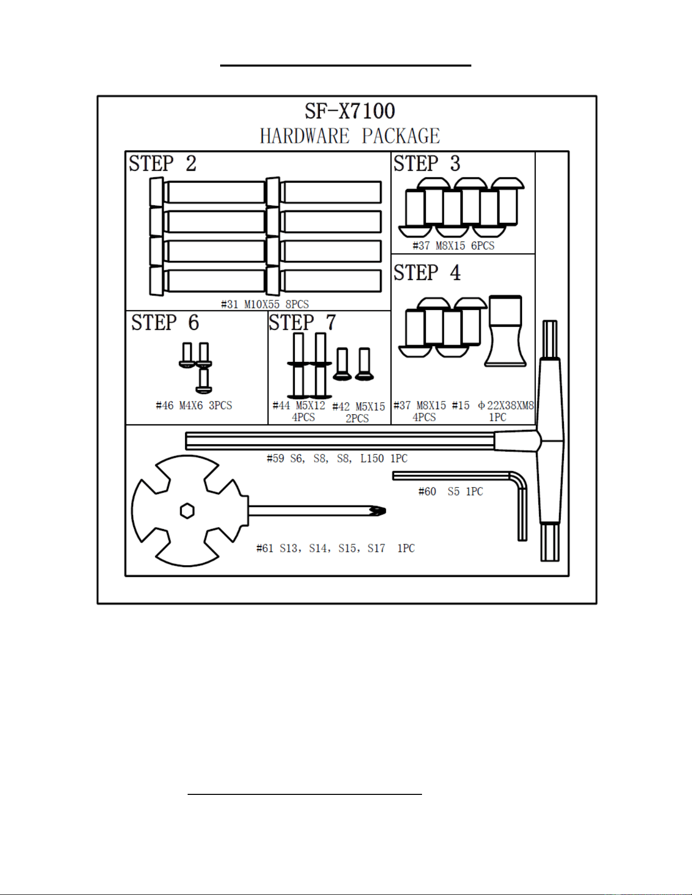
3
HARDWARE PACKAGE
Ordering Replacement Parts (U.S. and Canadian Customers only)
Please provide the following information in order for us to accurately identify the part(s)
needed:
✓ The model number (found on cover of manual)
✓ The product name (found on cover of manual)
✓ The part number found on the “EXPLODED DIAGRAM” (page 11) and “PARTS
LIST” (pages 12~13)
Please contact us at support@sunnyhealthfitness.com or 1-877-90SUNNY (877-907-
8669).
4
ASSEMBLY INSTRUCTIONS
We value your experience using Sunny Health and Fitness products. For assistance with parts or
troubleshooting, please contact us at suppo[email protected] or 1-877-90SUNNY (877-907-
8669).
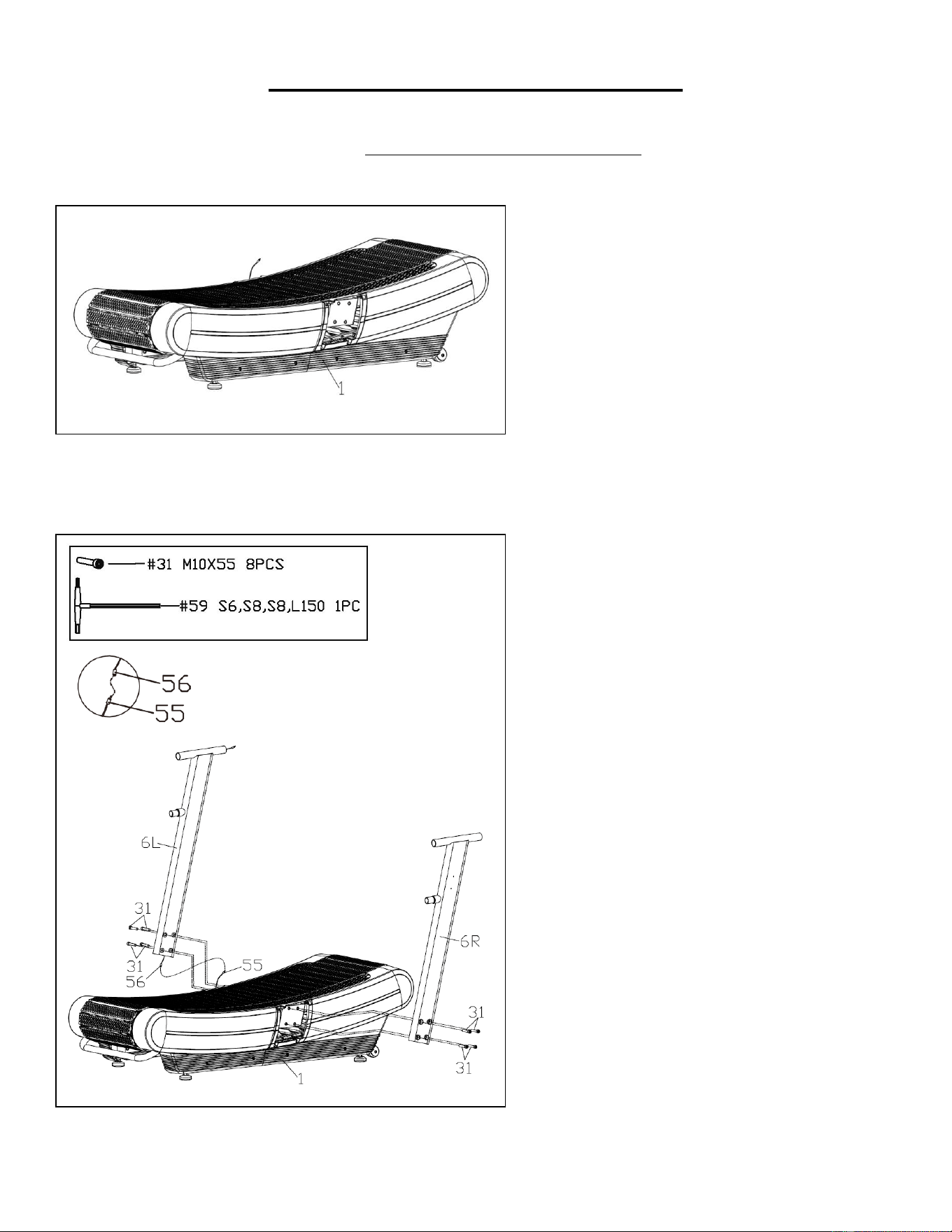
STEP 1:
We recommend having two people to do
the assembly.
Open the carton and remove contents.
Place the Main Frame (No. 1) on level
ground and ensure you have a clean and
adequate space.
STEP 2:
Connect the Sensor Wire (No. 55) to the
Middle Extension Wire (No. 56).
Attach Left and Right Upright Tubes (No.
6L & No. 6R) to the Main Frame (No. 1)
with 8 Inner Hex Bolts (No. 31) using T-
shaped Wrench (No. 59).
NOTE: Do not completely tighten the Inner
Hex Bolts (No. 31) yet.
5
We value your experience using Sunny Health and Fitness products. For assistance with parts or
troubleshooting, please contact us at suppo[email protected] or 1-877-90SUNNY (877-907-
8669).
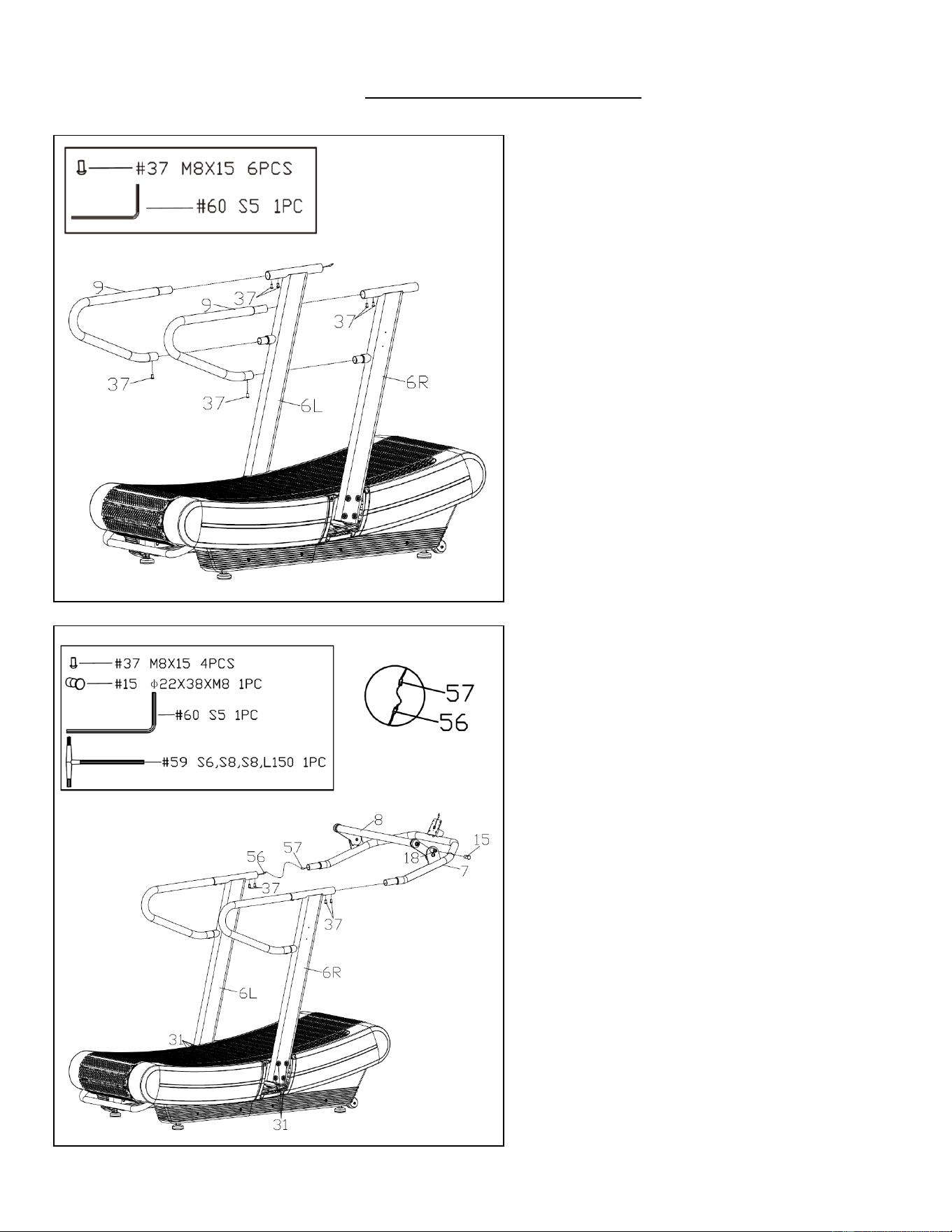
STEP 3:
Insert the Handrails (No. 9) into the
upper and lower connecting tubes of the
Left and Right Upright Tubes (No. 6L &
No. 6R) and then secure with 6 Hex Flat
Head Screws (No. 37) using Allen
Wrench (No. 60).
STEP 4:
Connect the Middle Extension Wire (No.
56) to the Upper Extension Wire (No.
57). Insert the wires inside the tubes of
the Handlebar Support (No. 7) and then
secure the Handlebar Support (No. 7) to
the Left and Right Upright Tubes (No.
6L & No. 6R) with 4 Hex Flat Head
Screws (No. 37) using Allen Wrench
(No. 60).
Now, fasten 8 Inner Hex Bolts (No. 31)
from STEP 2 tightly using T-shaped
Wrench (No. 59).
Screw the Spring Knob (No. 15) onto the
Bolt Pin (No. 18) and adjust the Front
Handlebar (No. 8) to a desired position.
6
We value your experience using Sunny Health and Fitness products. For assistance with parts or
troubleshooting, please contact us at suppo[email protected] or 1-877-90SUNNY (877-907-
8669).
Battery
Cover
38
Battery
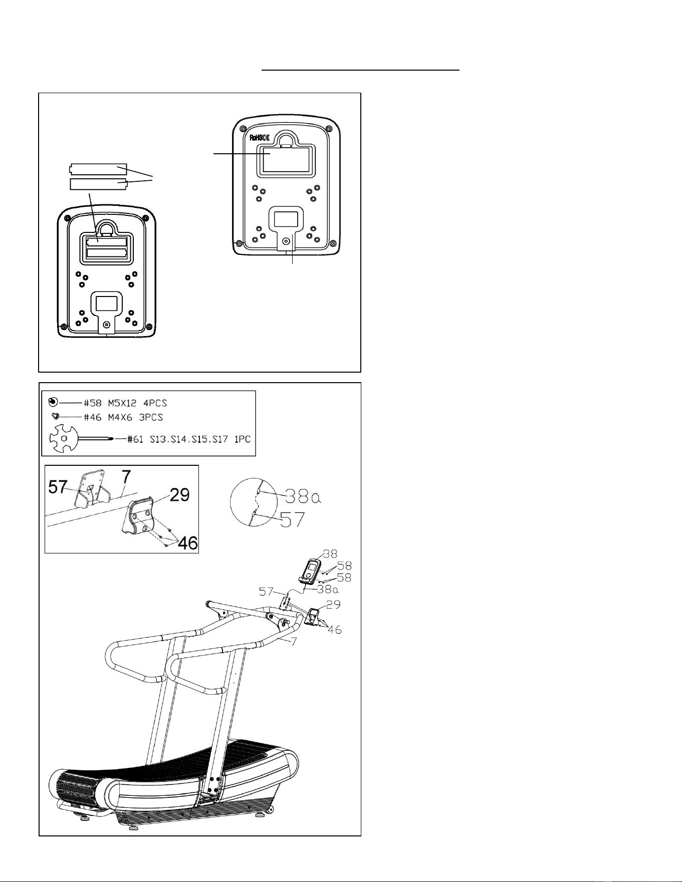
STEP 5:
Take out 2 AAA batteries from meter box.
Press down on the buckle of battery cover
on the Meter (No. 38), then remove battery
cover.
Install 2 AAA batteries into the battery case
on the back of the Meter (No. 38). Pay
attention to the battery + and – poles before
installing.
Press down on the buckle of battery cover,
then put the battery cover back on the back
of the Meter (No. 38).
STEP 6:
Remove 4 Cross Pan Head Screws (No.
58) from the Meter (No. 38) using the
Spanner (No. 61).
Connect the Upper Extension Wire (No.
57) with Meter Wire (No. 38a).
Insert the wires into the holes on the
bracket of Handlebar Support (No. 7).
Then attach the Meter (No. 38) to the
bracket of the Handlebar Support (No. 7)
with 4 Cross Pan Head Screws (No. 58)
that were just removed using the Spanner
(No. 61).
NOTE: Be careful not cut or pinch any wires
when attaching the Meter (No. 38).
Attach the Meter Cover (No. 29) to bracket
of the Handlebar Support (No. 7) with 3
Philips Screws (No. 46) using the
Spanner (No. 61).
NOTE: Be careful not pinch the Upper
Extension Wire (No. 57) when screwing
the 3 Philips Screws (No. 46) to mount the
Meter Cover (No. 29) onto the bracket of
the Handlebar Support (No. 7).
7
We value your experience using Sunny Health and Fitness products. For assistance with parts or
troubleshooting, please contact us at suppo[email protected] or 1-877-90SUNNY (877-907-
8669).
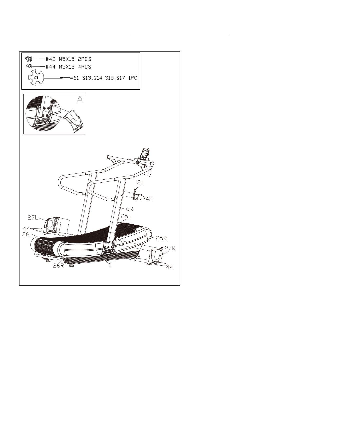
STEP 7:
Tilt the Left and Right Upright Tube
Covers (No. 27L & No. 27R) at an angle
as shown in Fig. A.
Align the clips of the Left and Right
Upright Tube Covers (No. 27L & No.
27R), Left and Right Front Covers (No.
25L & No. 25R) and Left and Right Rear
Covers (No. 26L & No. 26R) properly.
Then buckle the Left and Right Upright
Tube Covers (No. 27L & No. 27R) to the
Left and Right Front Covers (No. 25L &
No. 25R) and the Left and Right Rear
Covers (No. 26L & No. 26R).
Secure the Left and Right Upright Tube
Covers (No. 27L & No. 27R) to the Main
Frame (No. 1) with 4 Philips Screw (No.
44) using the Spanner (No. 61).
Finally, attach the Bottle Holder (No. 21)
to the Right Upright Tube (No. 6R) with 2
Philips Screws (No. 42) using the
Spanner (No. 61).
THE ASSEMBLY IS COMPLETE!
8
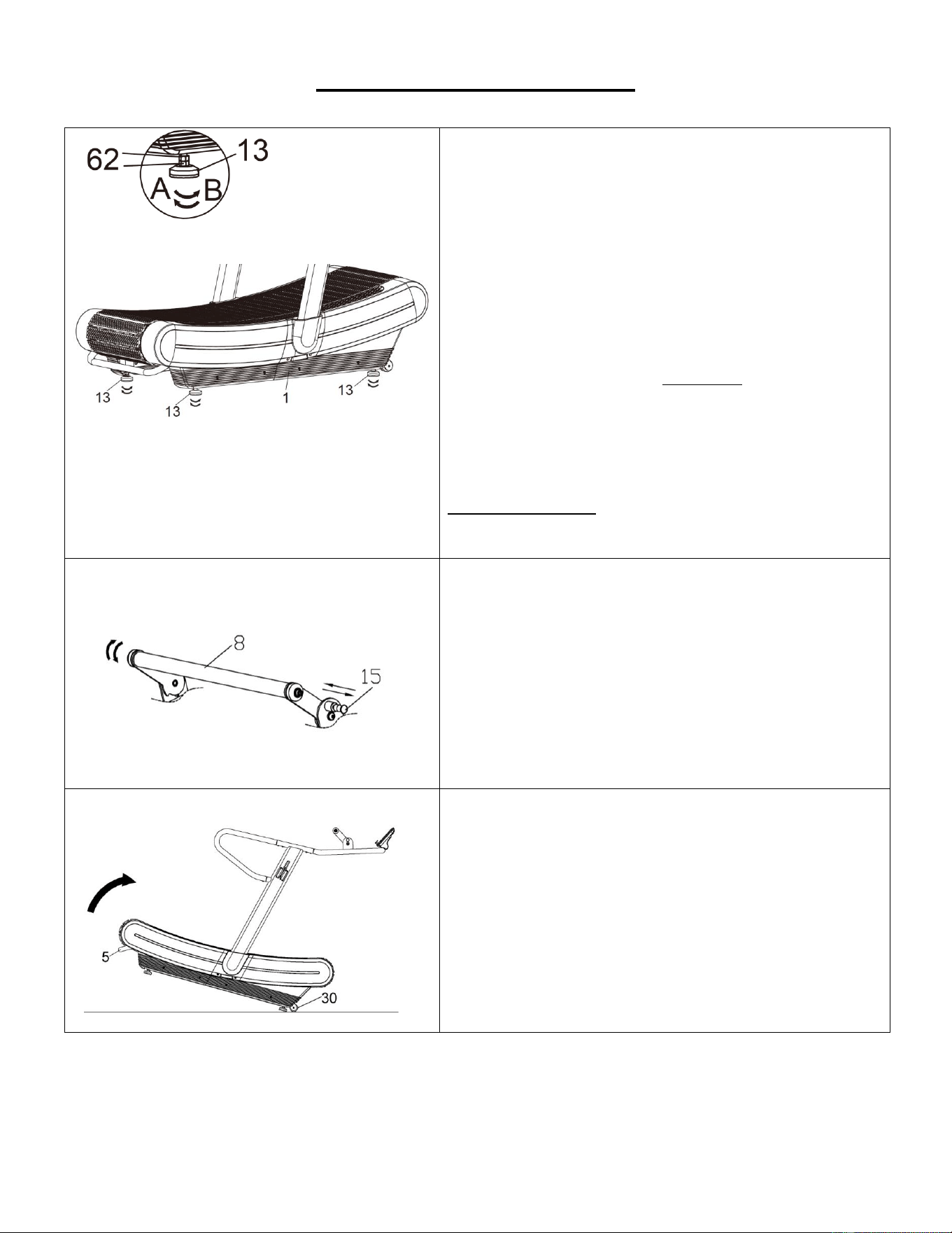
ADJUSTMENT GUIDE
ADJUSTING THE BALANCE
To achieve a smooth and comfortable use, you must
ensure that the treadmill is stable and secure. If you
notice that the treadmill is unbalanced during use,
you should adjust the Adjustable Pads (No. 13).
There are 4 Adjustable Pads (No. 13) located
beneath the Main Frame (No. 1). Simply rotate the
Adjustable Pad (No. 13) until the treadmill
becomes level with the floor surface. To do so,
loosen the 2 Hex Nuts (No. 62) on the Adjustable
Pad (No. 13) by turning it clockwise (direction A).
With the 2 Hex Nuts (No. 62) loosened, rotate
Adjustable Pad (No. 13) until it sits level with the
surface that the treadmill is on. When you have
finished adjusting the Adjustable Pad (No. 13), re-
tighten the 2 Hex Nuts (No. 62) by turning it
counter-clockwise (direction B). If necessary, repeat
this process to adjust the remaining Adjustable
Pads (No. 13).
ADJUSTING THE FRONT HANDLEBAR
To adjust the Front Handlebar (No. 8) forward or
backward, pull the Spring Knob (No. 15) outward,
then rotate the Front Handlebar (No. 8) to the
desired position. Once adjustment is complete, re-
insert the Spring Knob (No. 15) to secure the Front
Handlebar (No. 8) in place.
MOVING THE TREADMILL
NOTE: It is suggested to have two people to help
move the treadmill to avoid injury.
Lift the treadmill by the Rear Handlebar (No. 5) until
the Transportation Wheels (No. 30) touch the
floor. Now you can move the treadmill to your
desired location.
9
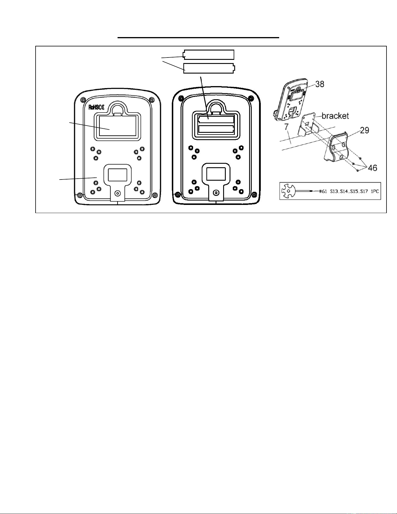
BATTERY REPLACEMENT
1. Remove 3 Philips Screw (No. 46) using Spanner (No. 61) and take off the Meter Cover (No. 29)
from the bracket of the Handlebar Support (No. 7).
2. Press down on the buckle of battery cover on the back of the Meter (No. 38), then remove battery
cover.
3. Remove the 2 old AAA batteries in the battery case and install 2 new AAA batteries into the battery
case on the back of the Meter (No. 38). Pay attention to the battery + and – poles before installing.
4. Press down on the buckle of battery cover, then put the battery cover back to the back of the Meter
(No. 38).
5. Attach the Meter Cover (No. 29) to the bracket of the Handlebar Support (No. 7) with 3 Philips
Screw (No. 46) that were just removed. Tighten and secure with Spanner (No. 61).
The replacement is complete!
BATTERY DISPOSAL
Dispose the batteries according to the laws and regulations of your local region. Some batteries may
be recycled. When disposing or recycling, do not mix battery types.
Battery
Cover
Battery
38
10
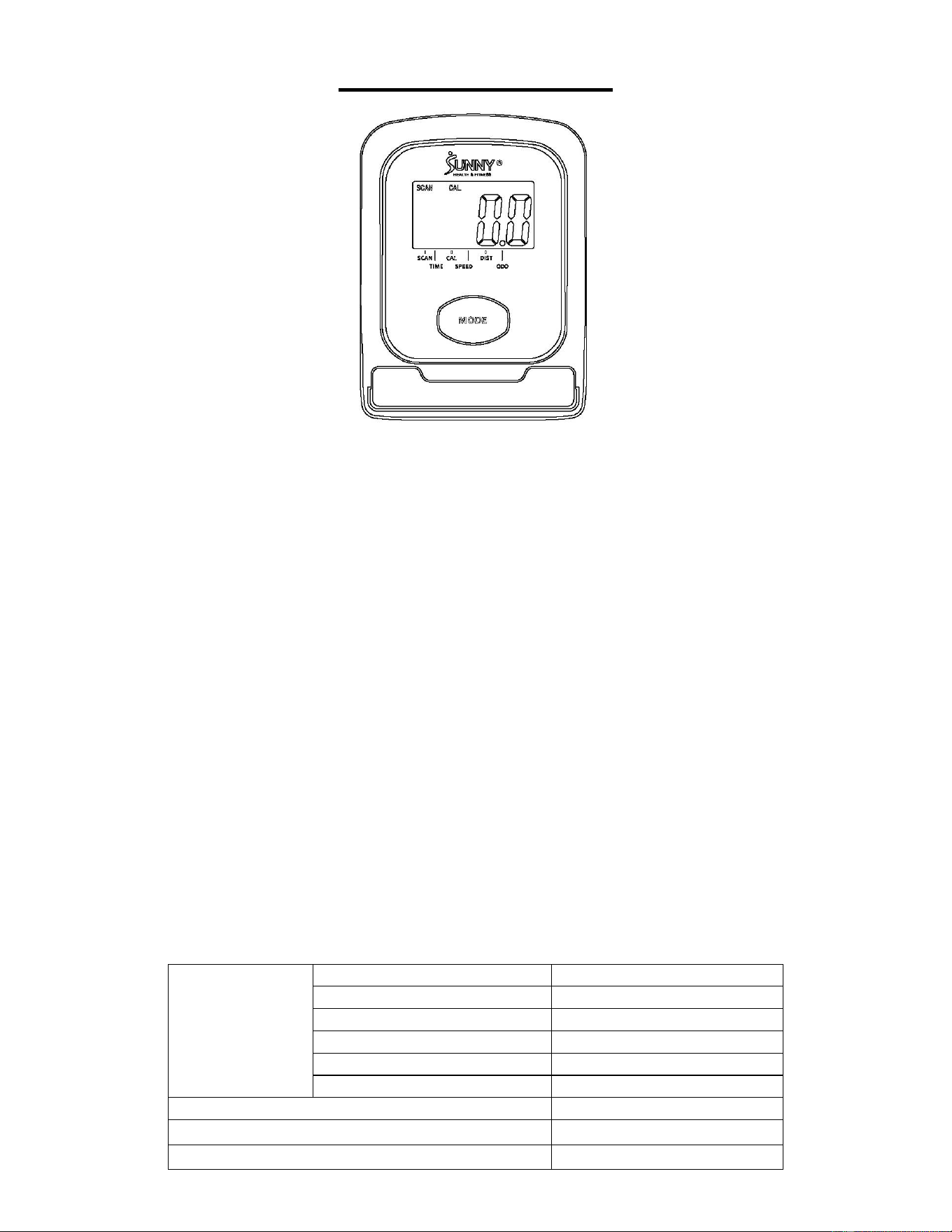
EXERCISE METER
KEY FUNCTION
● Press the MODE key to select function display value on LCD.
● Press and hold the MODE key for 3 seconds to reset all the values to zero (without resetting ODO
[TOTAL DISTANCE]).
SLEEP MODE
● The meter will turn off when the sensor receives no signal input, or no key is pressed for
approximately 4 minutes.
● The meter will turn on automatically when the MODE key is pressed or there is a signal input from
the sensor, while in sleep mode.
FUNCTION
1. SCAN: Display all function values in the following order every 6 seconds. TIME→SPEED→DIST
(DISTANCE)→CAL (CALORIES)→ODO (TOTAL DISTANCE).
2. TIME: The total working time since starting exercise.
3. SPEED: The current speed during exercise.
4. DIST (DISTANCE): The distance since starting this workout.
5. CAL (CALORIES): The calories burned since starting exercise.
6. ODO (TOTAL DISTANCE): The total distance of all workouts since batteries were installed. The
value will reset to zero, if the batteries are replaced.
SPECIFICATIONS
FUNCTION
SCAN
Every 6 seconds
TIME
0:00-99:59 (MIN:SEC)
SPEED
0.0~999.9 MILES/HOUR
DIST (DISTANCE)
0.00~999.9 MILES
ODO (TOTAL DISTANCE)
0.0~9999 MILES
CAL (CALORIES)
0.0~999.9 KCAL
BATTERY
SIZE – 2 AAA
OPERATING TEMPERATURE
0~40℃ (32℉-104℉)
STORAGE TEMPERATURE
-10~60℃ (14℉-140℉)
11
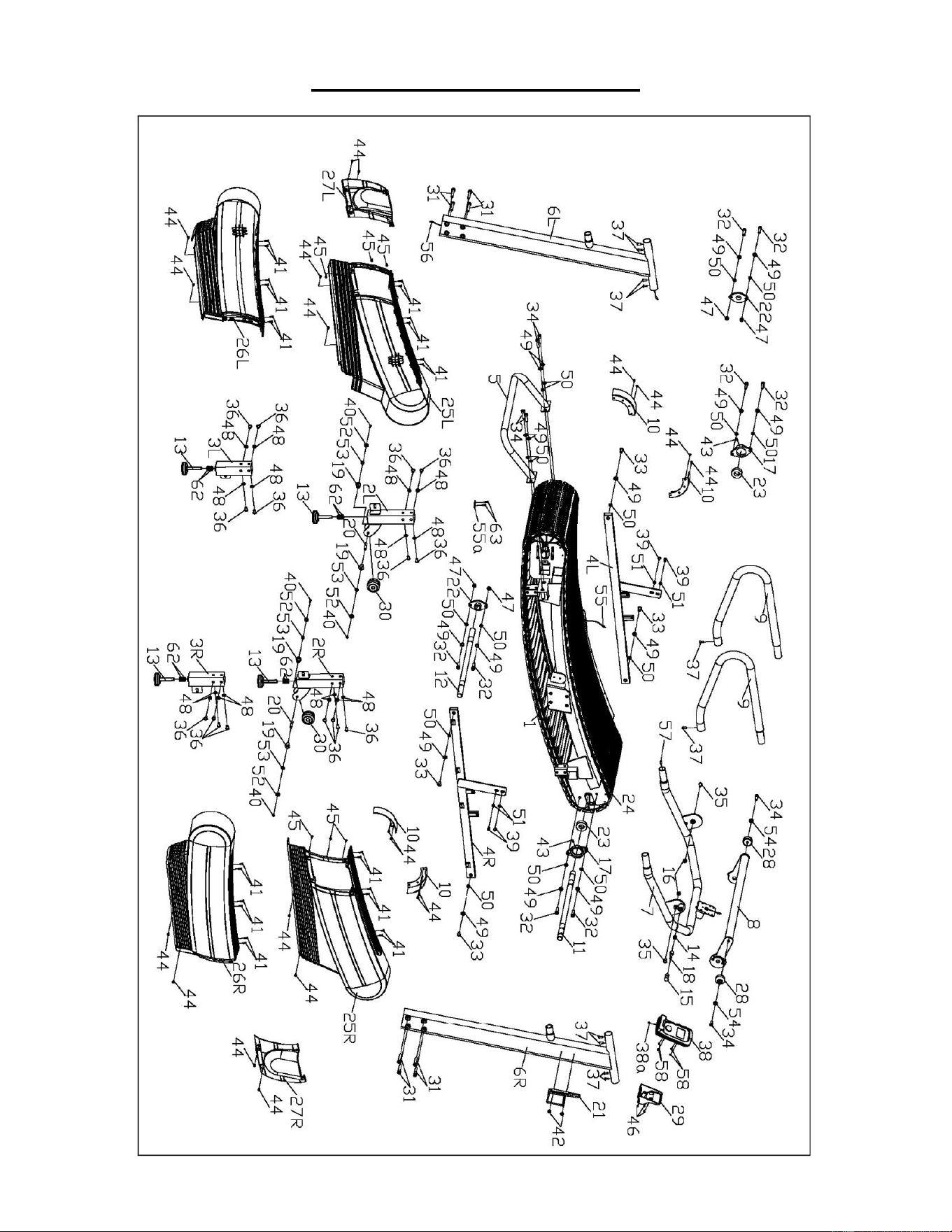
EXPLODED DIAGRAM

12
PARTS LIST
No.
Description
Specification
Qty.
No.
Description
Specification
Qty.
1
Main Frame
1
26L
Left Rear Cover
1
2L
Left Front Foot
Support
1
26R
Right Rear Cover
1
2R
Right Front Foot
Support
1
27L
Left Upright Tube
Cover
1
3L
Left Rear Foot
Support
1
27R
Right Upright Tube
Cover
1
3R
Right Rear Foot
Support
1
28
Round Cap
Φ45X25
2
4L
Left Base
Bracket
1
29
Meter Cover
1
4R
Right Base
Bracket
1
30
Transportation
Wheel
Φ61X40
2
5
Rear Handlebar
1
31
Inner Hex Bolt
M10X55
8
6L
Left Upright
Tube
1
32
Inner Hex Bolt
M10X35
8
6R
Right Upright
Tube
1
33
Inner Hex Pan
Head Bolt
M10X25
4
7
Handlebar
Support
1
34
Inner Hex Bolt
M10X25
6
8
Front Handlebar
1
35
Inner Hex Screw
M10X20
2
9
Handrail
2
36
Inner Hex Screw
M10X15
16
10
Protective Cover
4
37
Hex Flat Head
Screw
M8X15
10
11
Front Rotating
Axle
Φ25X570
1
38
Meter
BJHT038B
1
12
Rear Rotating
Axle
Φ25X570
1
38a
Meter Wire
100mm
1
13
Adjustable Pad
Φ60XM12X92
4
39
Inner Hex Screw
M8X15
4
14
Spring
Φ1.5XΦ15XL17.5
1
40
Inner Hex Screw
M6X16
4
15
Spring Knob
Φ22X38XM8
1
41
Cross Tapping
Screw
ST5.0X20
24
16
Spacer
Φ16.8XΦ10X7.0
2
42
Philips Screw
M5X15
2
17
One Way
Bearing Base
110X65X17
2
43
Set Screw
M5X15
2
18
Bolt Pin
Ф16X65
1
44
Philips Screw
M5X12
20
19
Roller Wheel
Spacer
Φ24XΦ15XΦ10.1
X22.3
4
45
Cross Tapping
Screw
ST4X12
6
20
Roller Wheel
Axle
Φ9.8X50XM6
2
46
Philips Screw
M4X6
3
21
Bottle Holder
1
47
Nylon Nut
M10
4
22
Bearing
FL005
2
48
Inner Serrated
Washer
Φ10
16
23
One Way
Bearing
6205
2
49
Flat Washer
Φ10
16
24
Aluminum Chain
60
50
Spring Washer
Φ10
16
25L
Left Front Cover
1
51
Inner Serrated
Washer
Φ8
4
25R
Right Front
Cover
1
52
Flat Washer
Φ6
4

13
Version 1.0
No.
Description
Specification
Qty.
No.
Description
Specification
Qty.
53
Spring Washer
Φ6
4
58
Cross Pan Head
Screw
M5X12
4
54
Flat Washer
Φ20XΦ10X1.5
2
59
T Shaped Wrench
S6, S8, S8, L150
1
55
Sensor Wire
1000mm
1
60
Allen Wrench
S5
1
55a
Sensor
1
61
Spanner
S13,S14,
S15,S17
1
56
Middle
Extension Wire
1500mm
1
62
Hex Nut
M12
8
57
Upper Extension
Wire
700mm
1
63
Philips Screw
ST4X12
2