

1
SMART ULTRA MANUAL
TREADMILL WITH 8 LEVELS
MAGNETIC RESISTANCE
SF-X7110
USER MANUAL
IMPORTANT! Please retain owner’s manual for maintenance and adjustment instructions. Your
satisfaction is very important to us, PLEASE DO NOT RETURN UNTIL YOU HAVE CONTACTED
US: [email protected] or 1-877-90SUNNY (877-907-8669).

1
IMPORTANT SAFETY INFORMATION
We thank you for choosing our product. To ensure your safety and health, please use this
equipment correctly. It is important to read this entire manual before assembling and using the
equipment. Safe and effective use can only be achieved if the equipment is assembled,
maintained, and used properly. It is your responsibility to ensure that all users of the equipment
are informed of all warnings and precautions.
1. Before starting any exercise program, you should consult your physician to determine if you
have any medical or physical conditions that could put your health and safety at risk or prevent
you from using the equipment properly. Your physician’s advice is essential if you are taking
medication that affects your heart rate, blood pressure, or cholesterol level.
2. Be aware of your body’s signals. Incorrect or excessive exercise can damage your health. Stop
exercising if you experience any of the following symptoms: pain, tightness in your chest,
irregular heartbeat, shortness of breath, lightheadedness, dizziness, or feelings of nausea. If
you do experience any of these conditions, you should consult your physician before
continuing with your exercise program.
3. Keep children and pets away from the equipment. The equipment is designed for adult use
only.
4. Use the equipment on a solid, flat level surface with a protective cover for your floor or carpet.
To ensure safety, the equipment should have at least 8 feet (240 cm) of free space behind it
and 2 feet (60 cm) on each side. Do not place the treadmill on any surface that blocks air
openings. To protect the floor or carpet from damage, place a mat under the treadmill.
5. Ensure that all nuts and bolts are securely tightened before using the equipment. The safety of
the equipment can only be maintained if it is regularly examined for damage and/or wear and
tear.
6. Always use the equipment as indicated. If you find any defective components while assembling
or checking the equipment, or if you hear any unusual noises coming from the equipment
during exercise, discontinue use of the equipment immediately and do not use until the
problem has been rectified.
7. Wear suitable clothing while using the equipment. Avoid wearing loose clothing that may
become entangled in the equipment.
8. Do not place fingers or objects into the moving parts of the equipment.
9. The maximum weight capacity of this unit is 330 lbs (150 kgs).
10. The equipment is not suitable for therapeutic use.
11. To avoid bodily injury and/or damage to the product or property, proper lifting and moving are
required.
12. Your product is intended for use in cool, dry conditions. You should avoid storage in extreme
cold, hot, or damp areas as this may lead to corrosion and other related problems.
13. This equipment is designed for indoor and home use only; it is not intended for commercial
use.
2
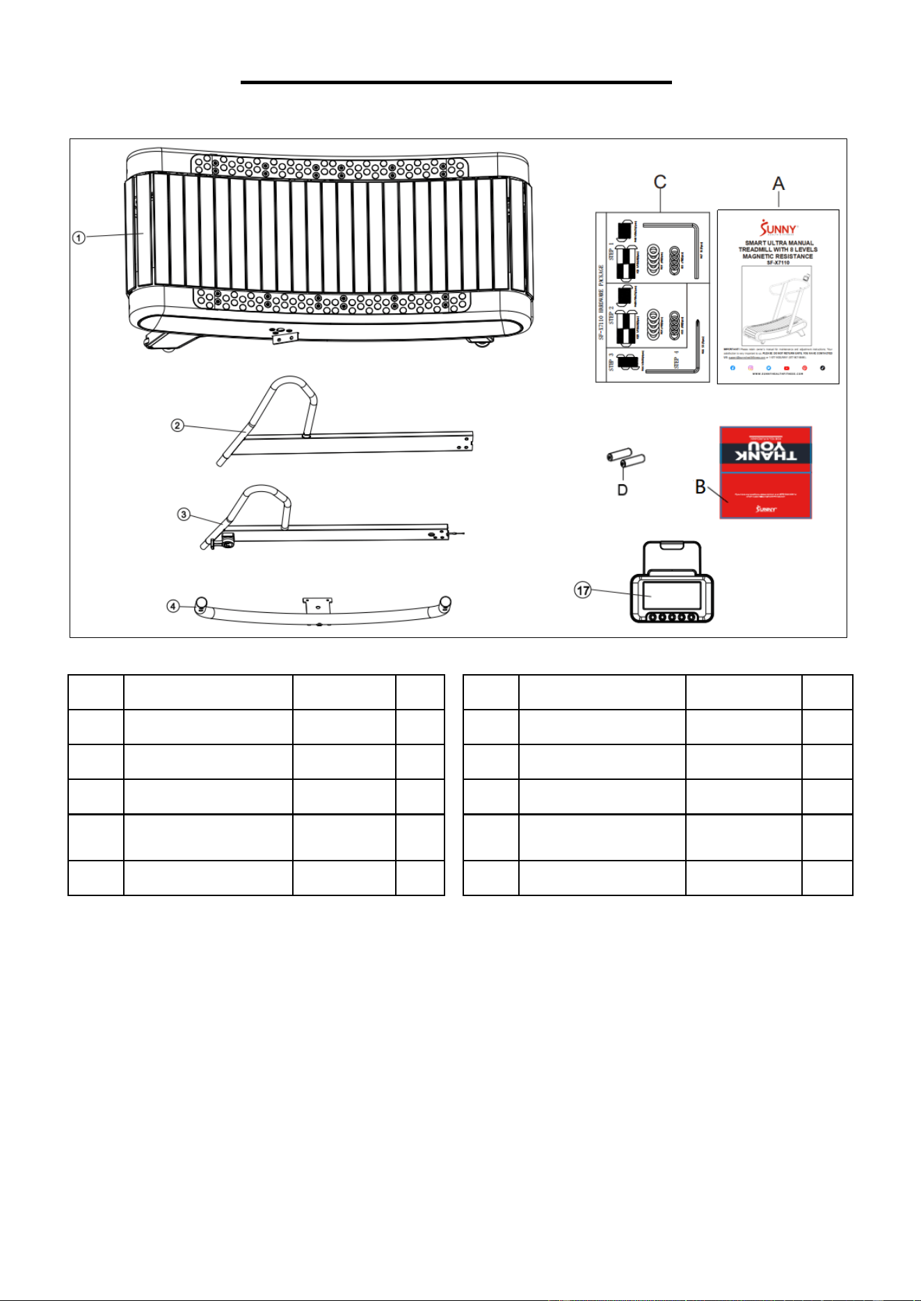
PRE-ASSEMBLY CHECKLIST
Before you start to assemble, please make sure all parts are included.
No.
Description
Spec.
Qty
No.
Description
Spec.
Qty
1
Main Frame
1
A
Manual
1
2
Left Upright Tube
1
B
Thank You Card
1
3
Right Upright Tube
1
C
Hardware Package
1
4
Computer Holder
Frame
1
D
Battery
AA
2
17
Computer
SF-L2402M
1
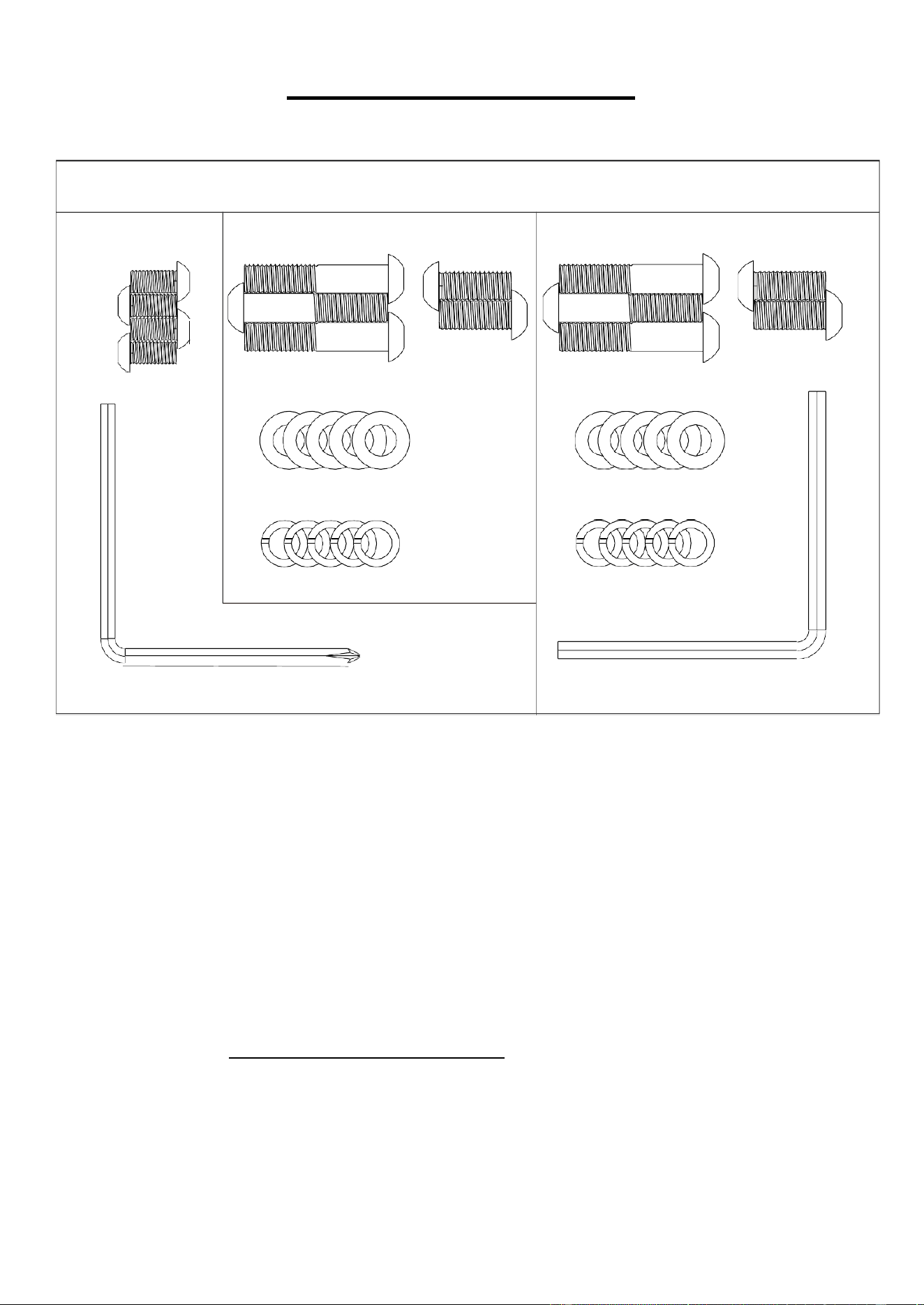
3
HARDWARE PACKAGE
Ordering Replacement Parts (U.S. and Canadian Customers only)
Please provide the following information in order for us to accurately identify the part(s) needed:
✓ The model number (found on cover of manual)
✓ The product name (found on cover of manual)
✓ The part number found on the “EXPLODED DIAGRAM” (page 14) and “PARTS LIST” (page
15)
Please contact us at support@sunnyhealthfitness.com or 1-877-90SUNNY (877-907-8669)
SF-X7110 HARDWARE PACKAGE
STEP 4
#40 M10x25(2pcs)
#39 M10x50(3pcs)
#44 M8x16(4pcs)
#51 ¢10(5pcs)
#55 ¢10(5pcs)
#67 S6 (1pcs)
#66 S5 (1pcs)
STEP 2
STEP 3
#39 M10x50(3pcs)
#51 ¢10(5pcs)
#55 ¢10(5pcs)
#40 M10x25(2pcs)
4
ASSEMBLY INSTRUCTIONS
We value your experience using Sunny Health and Fitness products. For assistance with parts or
troubleshooting, please contact us at suppo[email protected] or 1-877-90SUNNY (877-
907-8669).
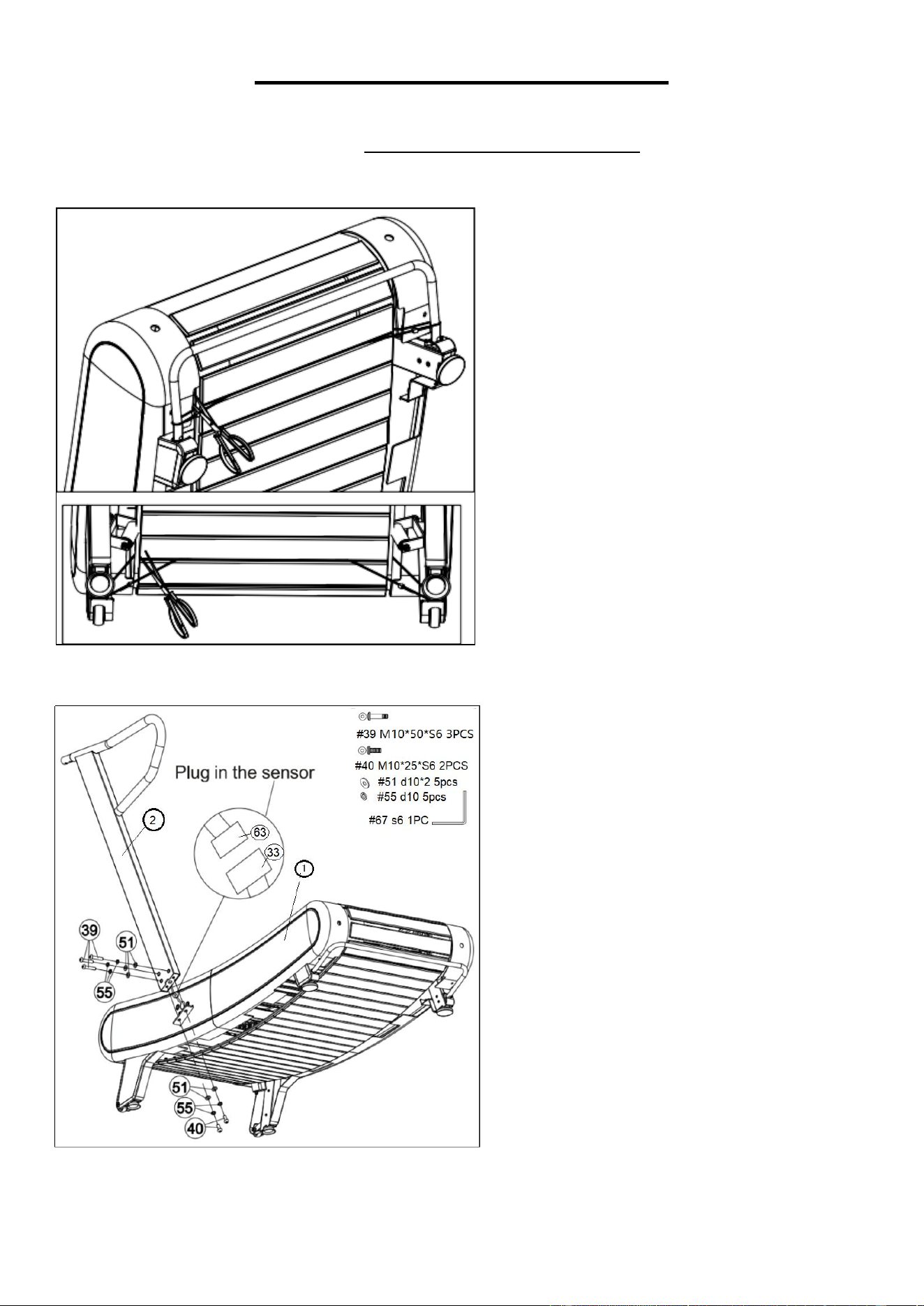
STEP 1:
We recommend having two people to do
the assembly.
Remove the Main Frame (No. 1) from
the carton on level ground and ensure a
clean and adequate space. Then follow
the direction of shown in the picture use
scissors to cut the 4 cable ties that hold
the running belt.
STEP 2:
Connect the Middle Sensor Wire 1 (No.
63) to the Sensor Wire (No. 33).
Attach the Left Upright Tube (No. 2)
onto the Main Frame (No. 1) with 3 Bolts
(No. 39), 2 Bolts (No. 40), 5 Spring
Washers (No. 55) and 5 Flat Washers
(No. 51). Then pre-secure with Allen
Wrench (No. 67).
NOTE: Do not clip the sensor wire
and completely tighten the Bolt (No.
39) and Bolt (No. 40) yet.
5
We value your experience using Sunny Health and Fitness products. For assistance with parts or
troubleshooting, please contact us at suppo[email protected] or 1-877-90SUNNY (877-
907-8669).
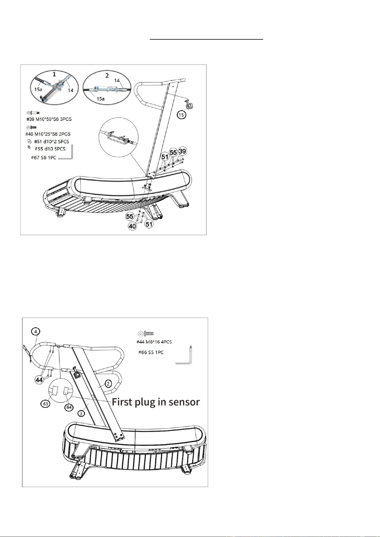
STEP 3:
CAUTION: Please make sure the Tension
Control Knob (No. 15) is at the highest
resistance level (level 8) before you
connect any wires together. Attach the
Tension Control Wire (No. 15a) into the
metal bracket of Tension Wire (No. 14) as
shown in drawing 1.
Then, pull Tension Control Wire (No. 15a)
upward and insert it into the slot of metal
bracket of Tension Wire (No. 14) as shown
in drawing 2. Make sure the metal fitting on
Tension Control Wire (No. 15a) is secured
in the metal bracket. Slide the Tension
Wire (No. 14) into the main frame.
Attach the Right Upright Tube (No. 3)
onto the Main Frame (No. 1) with 3 Bolts
(No. 39), 2 Bolts (No. 40), 5 Spring
Washers (No. 55) and 5 Flat Washers
(No. 51). Then pre-secure with Allen
Wrench (No. 67).
NOTE: Do not completely tighten the Bolt
(No. 39) and Bolt (No. 40) yet.
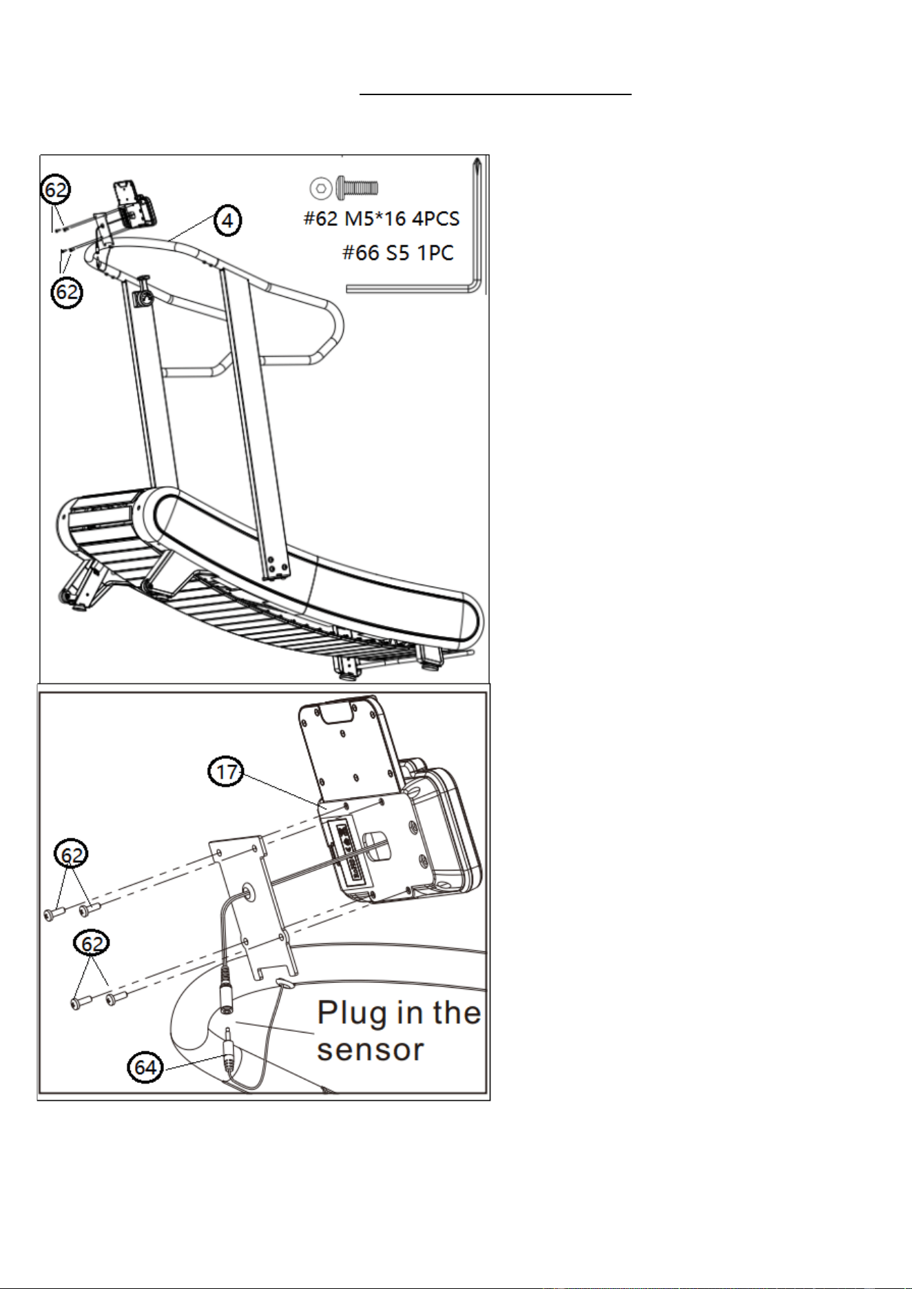
STEP 4:
Connect the Middle Sensor Wire 1 (No. 63)
with the Middle Sensor Wire 2 (No. 64).
Attach the Computer Holder Frame (No. 4)
onto the Left Upright Tube (No. 2) and the
Right Upright Tube (No. 3) with 4 Bolts
(No. 44). Tighten and secure with the Allen
Wrench (No. 66).
Now tighten the screws in steps 2 and 3.
6
We value your experience using Sunny Health and Fitness products. For assistance with parts or
troubleshooting, please contact us at suppo[email protected] or 1-877-90SUNNY (877-
907-8669).
STEP 5
STEP 5:
Remove the preinstalled 4 Bolts (No. 62)
from the black of computer with Allen
Wrench (No. 66).
Through the wire of the computer from the
middle hole on the bracket of the Computer
Holder Frame (No. 4), connect the
computer wire with the Middle Sensor
Wire 2 (No. 64) in the Computer Holder
Frame (No. 4),
Attach the Computer (No. 17) onto the
bracket of the Computer Holder Frame
(No. 4) with 4 Bolts (No. 62)
that were
removed. Tighten and
secure with Allen
Wrench (No. 66).
The assembly is complete!
7
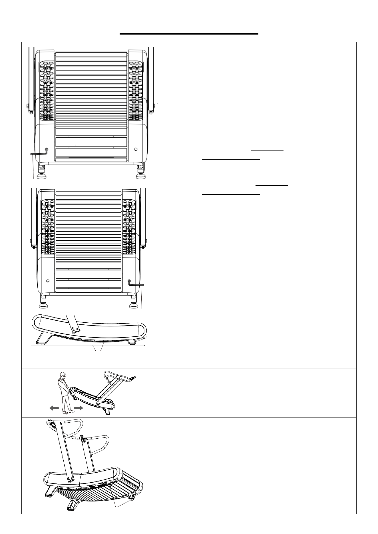
ADJUSTMENTS GUIDE
#67 S6
#67 S6
The lowest point of the running belt
must not touch the ground.
ADJUSTING THE RUNNING BELT
When you use a treadmill, the pressure on the running
belt is not balanced due to the different forces used by
the two feet during running, which causes the running
belt to deviate from the center. This deviation is
normal, and you need to bring the running belt back to
the center. Observe which side the running belt is
skewed while running.
If it is biased to the left, use the Allen Wrench (No.
67) to turn the left screw clockwise or turn the right
screw 1/4 counterclockwise;
If it is biased to the right, use the Allen Wrench (No.
67) to turn the right screw clockwise or turn the left
screw 1/4 counterclockwise;
If the running belt is still not in the middle, repeat the
above movements until it is adjusted to the middle.
After the adjustment, pay attention to whether the
lowest point of the running belt touches the ground. If
so, adjust both sides of the running belt clockwise at
the same time until can’t reach the ground.
MOVING THE TREADMILL
When moving the machine, grab the handrail with both
hands and lift the machine, then move it.
#27
ADJUSTING THE BALANCE
When the uneven ground causes the machine to tilt,
you can adjust the rear 2 Foot Pads (No. 27) to keep
the machine stable.
8
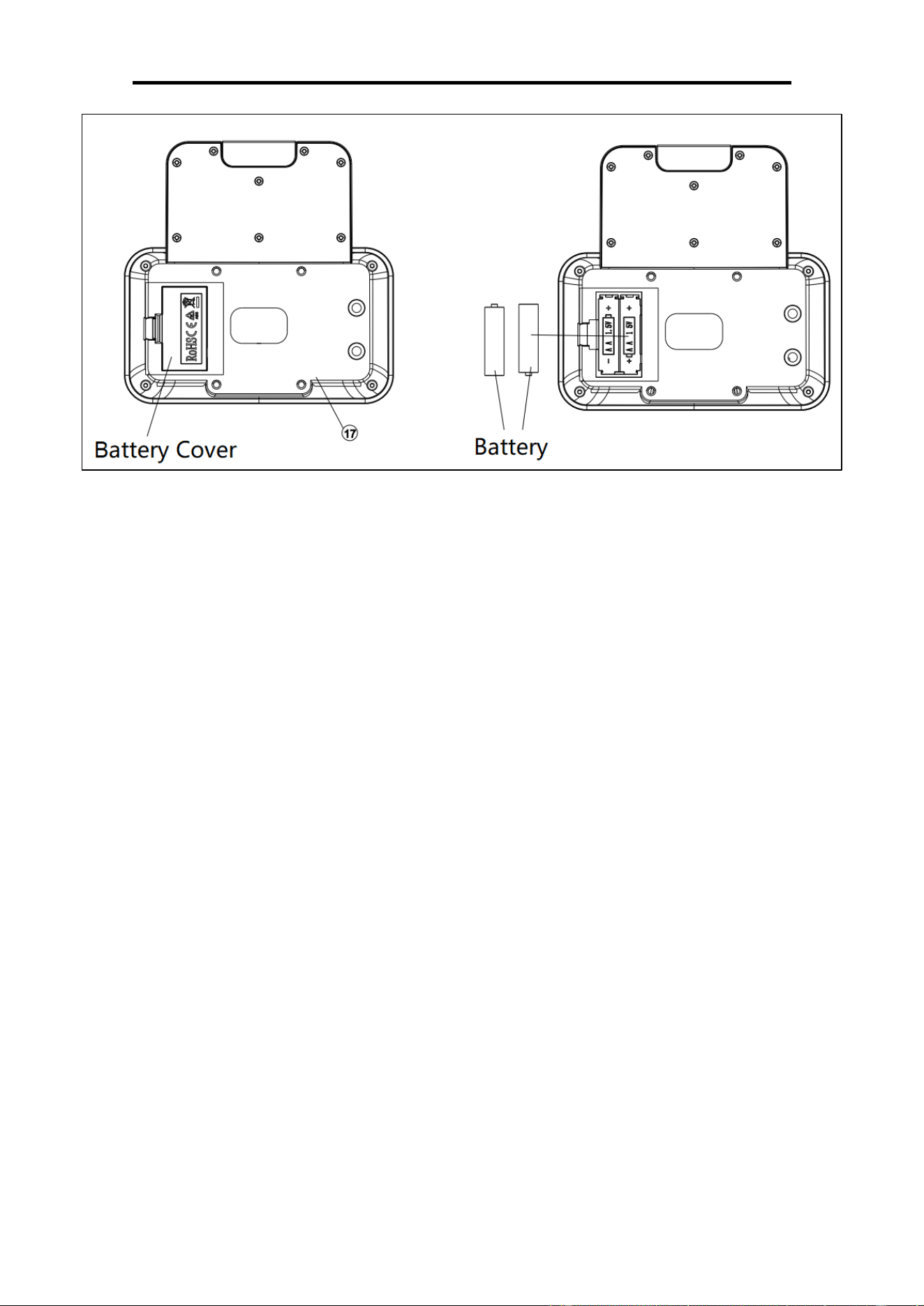
BATTERY INSTALLATION & REPLACEMENT
BATTERY INSTALLATION
1. Take out 2 AA batteries from the computer box.
2. Press the buckle of battery cover on the Computer (No. 17), then remove battery cover.
3. Install 2 AA batteries into the battery case on the back of the Computer (No. 17). Pay attention
to the battery + and – poles before installing.
4. Press the buckle of battery cover, then put the battery cover back to the back of the Computer
(No. 17).
The installation is complete!
BATTERY REPLACEMENT
1. Press the buckle of battery cover on the back of the Computer (No. 17), then remove battery
cover.
2. Remove the 2 old AA batteries in the battery case and install 2 new AA batteries into the battery
case on the back of the Computer (No. 17). Pay attention to the battery + and – poles before
installing.
3. Press the buckle of battery cover, then put the battery cover back to the back of the Computer
(No. 17).
The replacement is complete!
BATTERY DISPOSAL
NOTE: Always change both batteries at the same time. Do not mix battery types and do not mix
old and new batteries. Dispose batteries according to your state and regional guideline
9
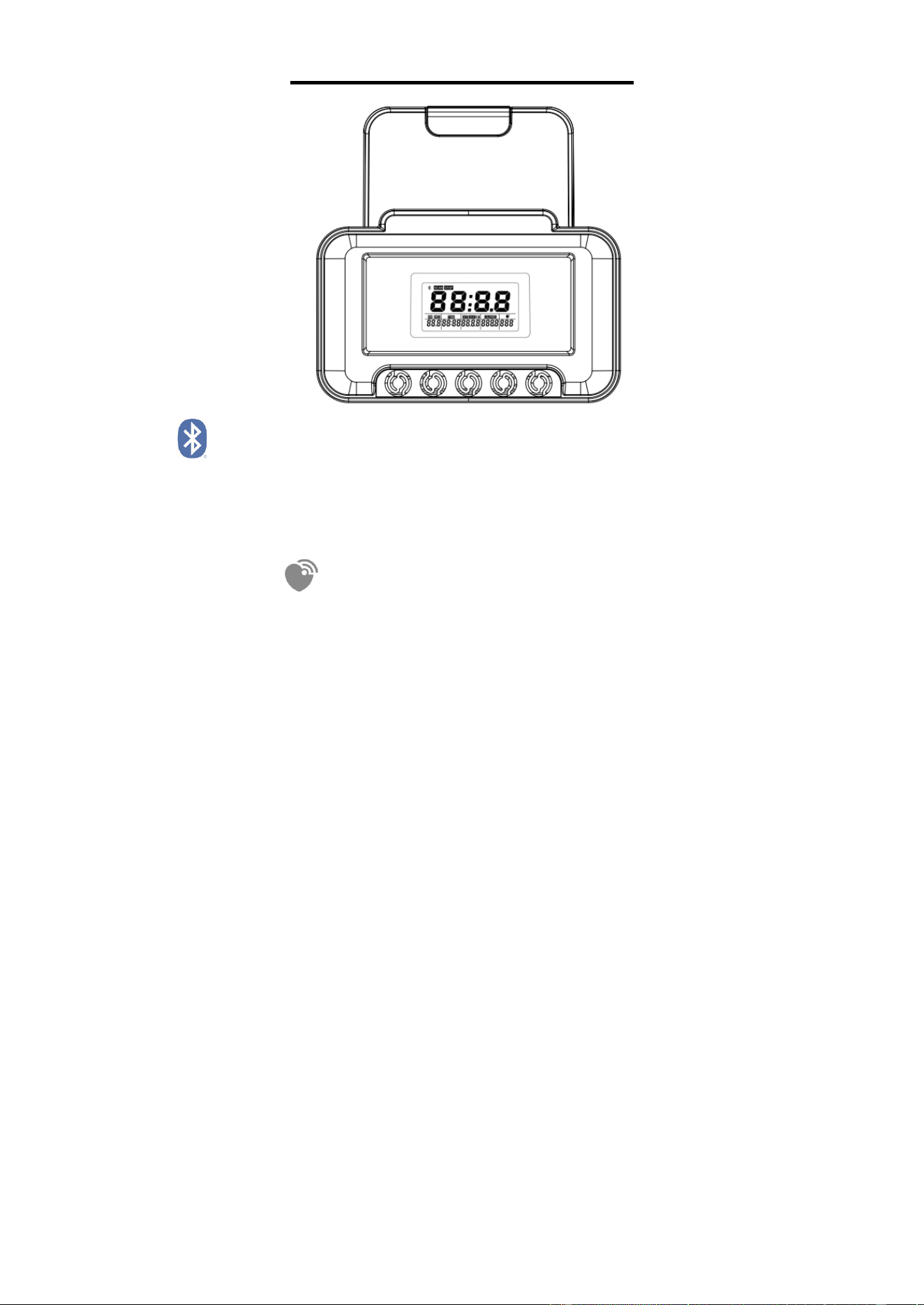
EXERCISE COMPUTER
BLUETOOTH :
1. The Bluetooth icon will flash when the computer is on or wakes from sleep mode. If no
Bluetooth connection is established within 3 minutes, the Bluetooth icon will turn off.
2. The Bluetooth icon will stay on when it is connected.
WIRELESS HEART RATE
1. The wireless heart rate icon will flash when the computer is on. If the heart rate monitor is not
connected within 1 minute, the wireless heart rate icon will turn off.
2. After exercise resumes, the wireless heart rate icon will flash. If the heart rate monitor is not
connected within 1 minute, the wireless heart rate icon will turn off.
3. When the computer wakes from sleep mode, the wireless heart rate icon will flash. If the heart
rate monitor is not connected within 1 minute, the wireless heart rate icon will turn off.
4. The wireless heart rate icon will flash when the MODE key is pressed. If the heart rate monitor
is not connected within 1 minute, the wireless heart rate icon will turn off.
5. The wireless heart rate icon will stay on when the heart rate monitor is connected.
NOTE: The heart rate monitor is not included. Wireless heart rate function works with SunnyFit
Heart Rate Monitor HR200. HR200 can only connect to the computer when the wireless heart rate
icon is flashing.
1. FUNCTION BUTTONS
1.1 RESET: Press and hold the key for 6 seconds to disconnect from both the SunnyFit APP
and the heart rate monitor; the the computer will enter sleep mode.
In the stopped state, click to return to the main menu to select the standby mode.
Hold down for 3 seconds to display the full display and enter the MANUAL mode to start
the movement.
Press and hold for 3 seconds in motion and pause mode to clear data, when the
Bluetooth disconnect.
1.2 START/STOP: Start/stop exercise; In the mode selection state, press the key to confirm
the selected mode.
1.3 MODE: Confirm the selected function and switch to the next function setting in the
TARGET mode setting.
1.4 UP/DOWN: Select Toggle function mode and set the TARGET value in Target mode,
when the Bluetooth disconnect.
10
2. FUNCTION
2.1 TIME:Displays the time of the exercise.
2.2 SPEED:Displays the speed at which you are moving.
2.3 CALORIES:Shows how many calories the user burned during exercise.
2.4 DISTANCE:Displays the distance of the exercise.
2.5 PACE:Pace (The time it takes to move one mile).
2.6 PULSE: Displays the user heart rate.
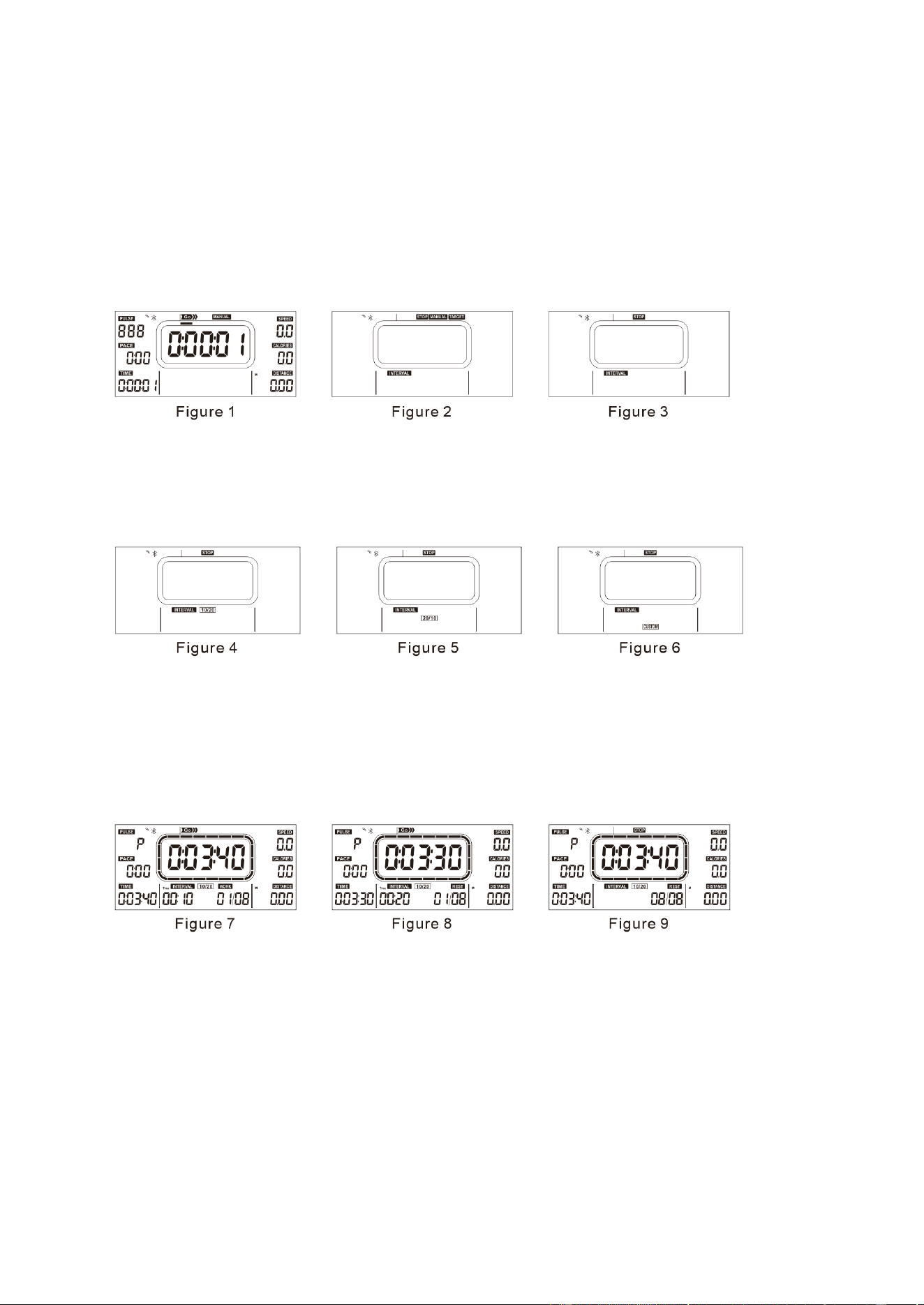
3. OPERATION
3.1 MANUAL Mode : After the battery is installed, the computer display interface will jump
directly into the manuall mode (Figure 1), and you can start to move at this time.
3.2 INTERVAL Mode : Press the "START/STOP" key to STOP the movement, and then
press the "RESET" key to return to the main menu (Figure 2). At this time, press the "UP"
or "DOWN" key to select the INTERVAL mode (Figure 3) and press the "START/STOP"
key to enter. After entering inervalt mode, you can switch between two pre-set modes
(10/20, 20/10) (Figure 4, Figure 5) and one CUSTOM mode (CUSTOM) (Figure 6).
3.2.1 INTERVAL 10/20 MODE
A. In INTERVAL mode, select 10/20 mode and press START/STOP key to start the
movement. The computer displays READY and counts down for 3 seconds.
B. When the countdown ends, the main screen displays "WORK" and "01/08" at the bottom of
the main screen, and the countdown starts for 10 seconds (Figure 7);
C. When the 10-seconds countdown ends, "REST" and "01/08" are displayed at the bottom of
the main screen and the 20-seconds countdown starts (Figure 8);
D. B and C continue to cycle, and the cumulative times of each cycle will be increased by one
until "WORK 08/08" is displayed at the bottom of the main screen. After the movement is
over, the end interface will be entered (Figure 9). At this time, press "START/STOP" key to
restart the movement in the current mode.
3.2.2 INTERVAL 20/10 MODE
A. In INTERVAL mode, select the "20/10" mode and press the "START/STOP" key to start the
movement. The computer displays "READY" and countdown for 3 seconds.
B. When the countdown ends, the main screen displays "WORK" and "01/08" at the bottom of
the main screen, and the countdown starts for 20 seconds (Figure 10).
C. When the 20-seconds countdown ends, "REST" and "01/08" are displayed at the bottom of
the main screen and the 10-seconds countdown begins (Figure 11);
D. B and C continue to cycle, and the cumulative times of each cycle will be increased by one
until "WORK 08/08" is displayed at the bottom of the main screen. After the movement is
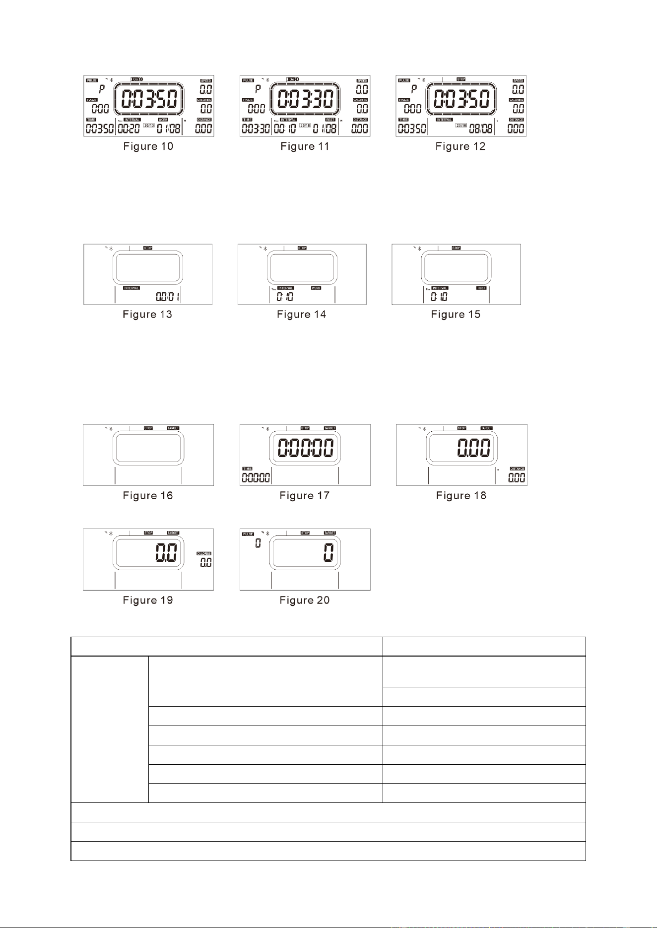
11
over, the end screen will be entered (Figure 12). At this time, press "START/STOP" key to
restart the movement in the current mode.
3.2.3 INTERVAL CUSTOM MODE
In INTERVALmode, select "CUSTOM" mode and press "START/STOP" key to set the
number of intermittent alternation (Figure 13). After setting, press "MODE" key to set
"WORK TIME" (Figure 14). Press the "MODE" key to set "REST TIME" (Figure 15), and
press the "START/STOP" key to start the movement.
3.3 TARGET MODE
On the standby screen, select "TARGET" MODE (Figure 16) and press "START/STOP"
key to confirm entering the function setting screen to set the target value of the
corresponding function (Figure 17-20); press "MODE" key to switch to select the function to
set the target value; press "UP" or "DOWN" key to set the corresponding target value.
Press the “START/STOP” key to start the movement.
4. COMPUTER PARAMETER:
Indication range
Setting range
Function
TIME
0:00:00~2:00:00
Target pattern
0:05:00~2:00:00(0:05:00)
INTERVAL 0:10~9:59 (0:01)
SPEED
0.0~99.9 Miles per hour
CALORIES
0.0~999.9 CAL
0.0-100.0 CAL
DISTANCE
0.00~999.99 Miles
1.00~100.00 Miles
PACE
0:00~99:59
PULSE
40-240 BPM
60-240 BPM (5BPM)
Battery Model
2 AA batteries
Operating Temperature
0°C ~ +40°C/32°F ~ 104°F
Storage Temperature
-10°C ~ +60°C/14°F ~ 140°F

12
APP CONNECTION:
Connect Smart Equipment to SunnyFit App:
1. Scan to download SunnyFit from the app store:
2. Ensure that the Bluetooth function is turned on from your mobile device.
3. If this is your first time using the SunnyFit app, follow the in-app instructions to register for
your free SunnyFit account and log in.
4. Begin any workout activity that matches your smart equipment, then follow the onscreen
prompts to search for and connect to your smart equipment.
5. When connected, your stats and records will be displayed at the end of your
course/session, and recorded in your account profile!
Troubleshooting:
⚫ If you are having trouble connecting your smart equipment, visit www.sunnyfit.com/guide or
scan the QR code below:
⚫ If you require additional support, please contact [email protected]

13
MAINTENANCE INSTRUCTIONS
This is general information for daily, monthly maintenance to be performed on your treadmill.
MONTHLY MAINTENANCE
Check all hardware is solid, such as: column, table frame, handrail;
Check the running belt for signs of wear;
Remove foreign matter accumulated on the running belt.
DAILY MAINTENANCE
After each workout, wipe all areas: running platform, handrails, console. Pay special attention
to running with protection.
Sweat is highly corrosive and may cause problems that need to be
replaced later.
All treadmills should be adjusted before leaving the factory and after installation, but after a
period of use, it may also run off. The reasons causing the running belt deviation phenomenon
are:
The host is not stable;
The user's feet are not in the center of the running belt when exercising;
The user's two feet are not using the same force. It artificially causes a runoff. One foot pedals
the empty belt for a few minutes to return to normal. For a runaway that cannot be
automatically restored, apply the Allen Wrench (No. 67) in the random belt # 64 S6 to
gradually adjust at 90° one grille.
14
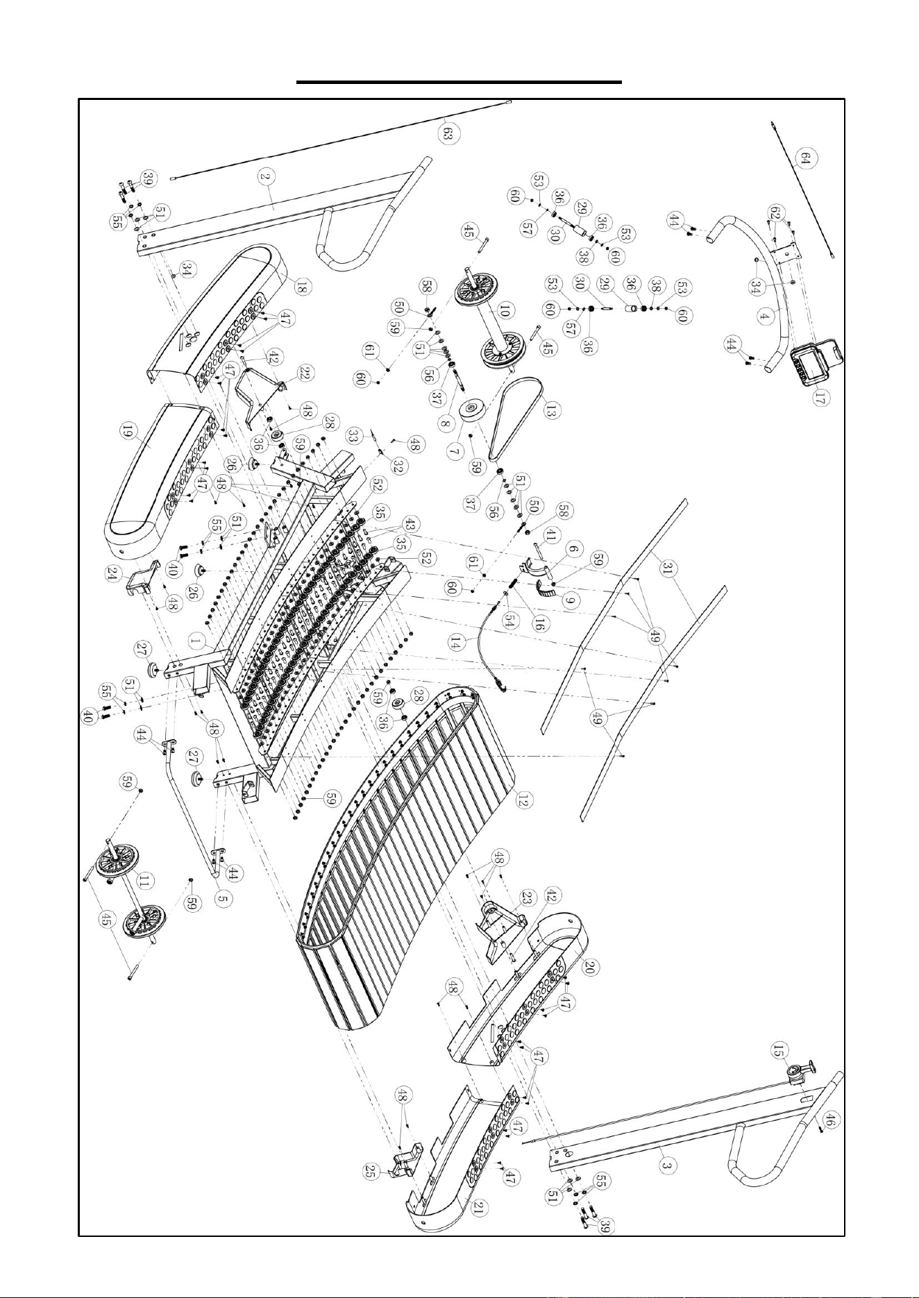
EXPLODED DIAGRAM

15
PARTS LIST
Version 1.0
No.
Description
Spec.
Qty.
1
Main Frame
1
2
Left Upright Tube
1
3
Right Upright Tube
1
4
Computer Holder Frame
1
5
Rear Handle
1
6
Magnetic Frame
1
7
Flywheel
1
8
Flywheel Axle
1
9
Magnet
24x9x4.5mm
15
10
Front Roller
1
11
Rear Roller
1
12
Track Assembly
1
13
V-belt
1
14
Tension Wire
1
15
Tension Control Knob
1
15a
Tension Control Wire
1
16
Spring
1
17
Computer
SF-L2402M
1
18
Left Front Guard
1
19
Left Rear Guard
1
20
Right Front Guard
1
21
Right Rear Guard
1
22
Left Front Lower Cover
1
23
Right Front Lower Cover
1
24
Left Rear Lower Cover
1
25
Right Rear Lower Cover
1
26
Suction Cup Pad
2
27
Foot Pads
2
28
Handling Wheels
2
29
Guide Belt Jacket
2
30
Guide Belt Inner Shaft
2
31
Shelter Bar
2
32
Sensor Mounting Seat
1
33
Sensor Wire
1
No.
Description
Spec.
Qty.
34
Protective Coil
3
35
Gummed Bearing
60
36
Deep Groove Ball Bearing
608
8
37
Deep Groove Ball Bearing
6000
2
38
Guide Wheel Washer
2
39
Bolt
M10x50
6
40
Bolt
M10x25
4
41
Bolt
M8x80
1
42
Bolt
M8x40
2
43
Bolt
M8x22
60
44
Bolt
M8x16
8
45
Bolt
M8x70
4
46
Bolt
M5x25
1
47
Screw
ST4.8x13
24
48
Screw
ST4.2x13
23
49
Screw
ST4.2x16
8
50
Lifting Bolt
M6x45
2
51
Flat Washer
Ф10
20
52
Flat Washer
Ф8
60
53
Flat Washer
Ф6
4
54
Large Fat Washer
Ф6
1
55
Spring Washer
Ф10
10
56
Elastic Retaining Ring
Ф10
2
57
Elastic Retaining Ring
Ф8
4
58
Nut
M10
2
59
Nut
M8
67
60
Nut
M6
6
61
Nut
M6
2
62
Bolt
M5x16
4
63
Middle Sensor Wire 1
1
64
Middle Sensor Wire 2
1
66
Allen Wrench
S5
1
67
Allen Wrench
S6
1