
1
IMPORTANT SAFETY INFORMATION
We thank you for choosing our product. To ensure your safety and health, please use this
equipment correctly. It is important to read this entire manual before assembling and using the
equipment. Safe and effective use can only be achieved if the equipment is assembled,
maintained, and used properly. It is your responsibility to ensure that all users of the equipment
are informed of all warnings and precautions.
1. Before starting any exercise program, you should consult your physician to determine if you
have any medical or physical conditions that could put your health and safety at risk or
prevent you from using the equipment properly. Your physician’s advice is essential if you are
taking medication that affects your heart rate, blood pressure, or cholesterol level.
2. Be aware of your body’s signals. Incorrect or excessive exercise can damage your health.
Stop exercising if you experience any of the following symptoms: pain, tightness in your
chest, irregular heartbeat, shortness of breath, lightheadedness, dizziness, or feelings of
nausea. If you do experience any of these conditions, you should consult your physician
before continuing with your exercise program.
3. Keep children and pets away from the equipment. The equipment is designed for adult use
only.
4. Use the equipment on a solid, flat level surface with a protective cover for your floor or carpet.
To ensure safety, the equipment should have at least 8 feet (240 cm) of free space all around
it.
5. Ensure that all nuts and bolts are securely tightened before using the equipment. The safety
of the equipment can only be maintained if it is regularly examined for damage and/or wear
and tear.
6. Always use the equipment as indicated. If you find any defective components while
assembling or checking the equipment, or if you hear any unusual noises coming from the
equipment during exercise, discontinue use of the equipment immediately and do not use
until the problem has been rectified.
7. Wear suitable clothing while using the equipment. Avoid wearing loose clothing that may
become entangled in the equipment.
8. Do not place fingers or objects into the moving parts of the equipment.
9. The maximum weight capacity of this unit is 300 lbs (135 kgs).
10. The equipment is not suitable for therapeutic use.
11. To avoid bodily injury and/or damage to the product or property, proper lifting and moving are
required.
12. Your product is intended for use in cool and dry conditions. You should avoid storage in
extreme cold, hot or damp areas as this may lead to corrosion and other related problems.
13. This equipment is designed for indoor and home use only, it is not intended for commercial
use.
2
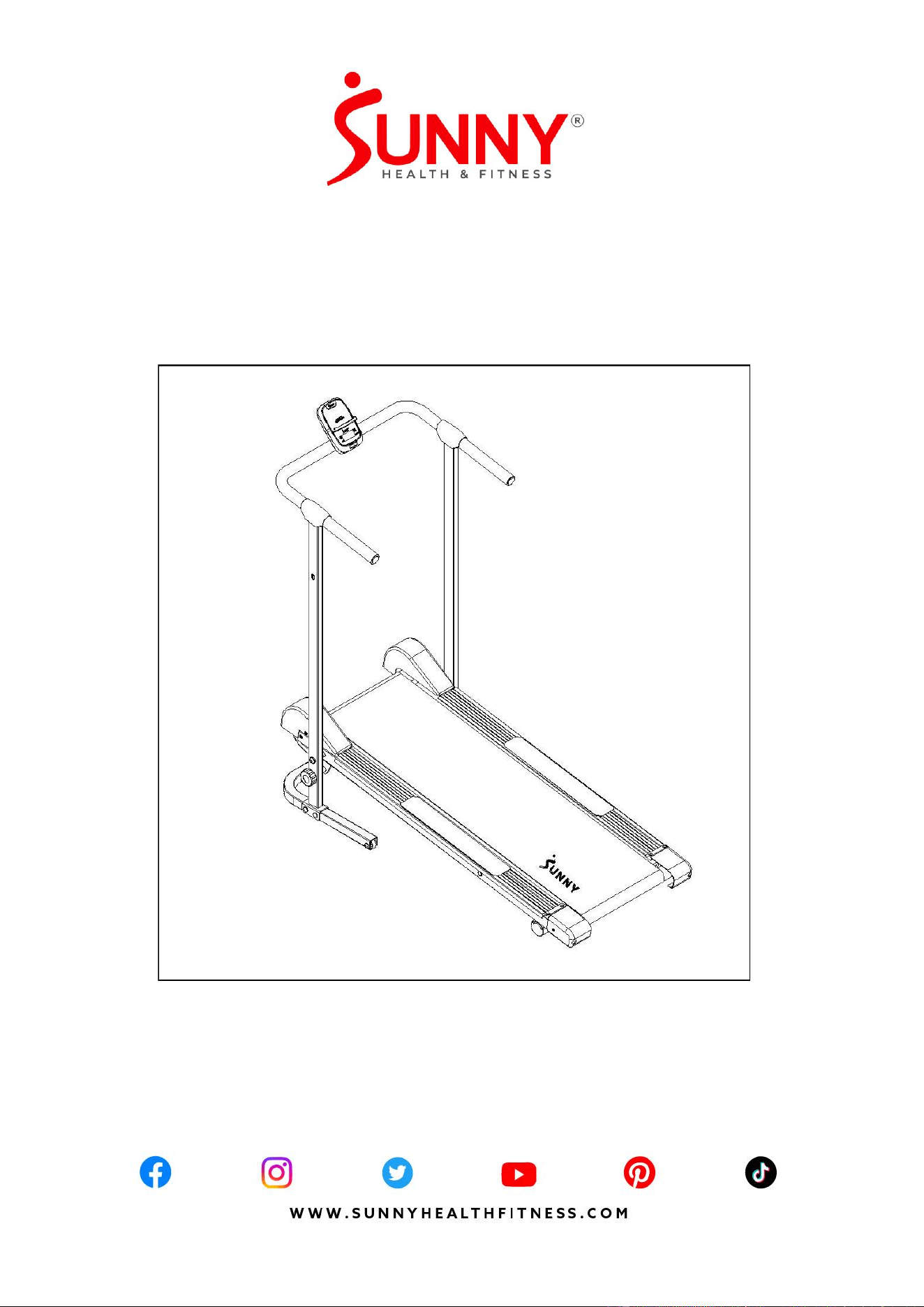
PRE-ASSEMBLY CHECK LIST
No.
Description
Spec.
Qty.
No.
Description
Spec.
Qty.
1
Main Frame
1
10
Lock Knob
1
3L
Left Flywheel Cover
1
23
Base Frame
1
3R
Right Flywheel Cover
1
A
Hardware Package
1
4
Right Upright Support
1
B
Battery
AAA
2
5
Left Upright Support
1
C
Thank You Card
1
6
Handlebar
1
D
User Manual
1
7
Decorative Cover
2
E
Oil Bottle
1
8
Computer
1
3
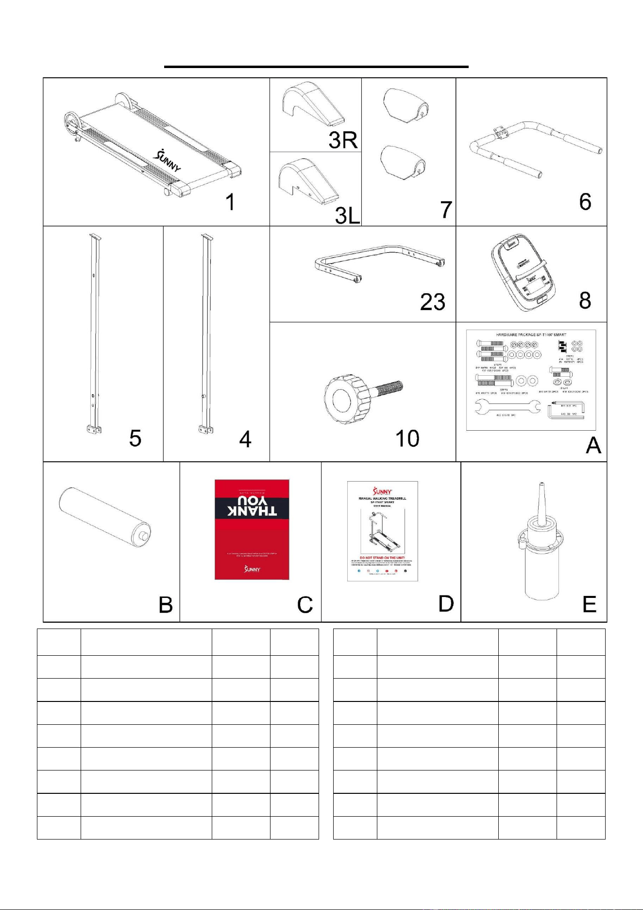
HARDWARE PACKAGE
Ordering Replacement Parts (U.S. and Canadian Customers only)
Please provide the following information in order for us to accurately identify the part(s) needed:
✓ The model number (found on cover of manual)
✓ The product name (found on cover of manual)
✓ The part number found on the “EXPLODED DIAGRAM” (page 13) and “PARTS LIST” (page
12).
4
ASSEMBLY INSTRUCTIONS
We value your experience using Sunny Health and Fitness products. For assistance with parts or
troubleshooting, please contact us at [email protected] or 1-877-90SUNNY (877-
907-8669).
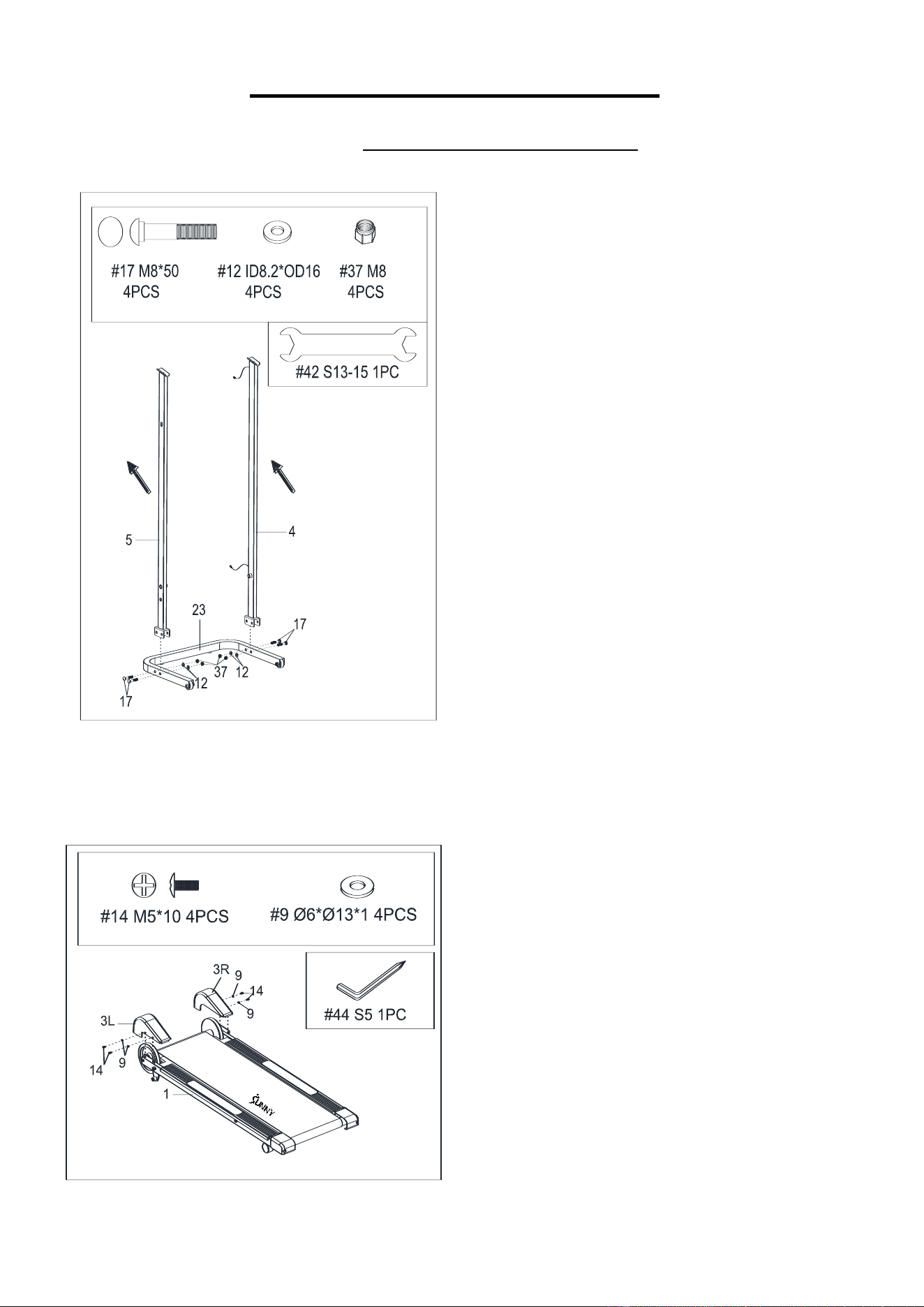
STEP 1:
Note: To complete steps that involve
assembling heavy components, have a second
person help with the assembly process. For
your safety, do NOT attempt to complete these
steps on your own.
CAUTION: Left Upright Support (No. 5) is
marked with “L” and Right Upright Support
(No. 4) is marked with “R”.
Please make sure that the arrow point on the
L/R labels should face forward before
assembling.
Secure the Right & Left Upright Supports
(No. 4 & No. 5) to the Base Frame (No. 23)
using 4 Carriage Bolts (No. 17), 4 Flat
Washers (No. 12), and 4 Nylon Nuts (No. 37).
Tighten and secure with Spanner (No. 42).
STEP 2:
Secure the Left & Right Flywheel Covers (No.
3L & No. 3R) to the Main Frame (No. 1) using
4 Phillips Head Screws (No. 14) and 4
Washers (No. 9). Tighten and secure with
Allen Wrench (No. 44).
5
We value your experience using Sunny Health and Fitness products. For assistance with parts or
troubleshooting, please contact us at [email protected] or 1-877-90SUNNY (877-
907-8669).
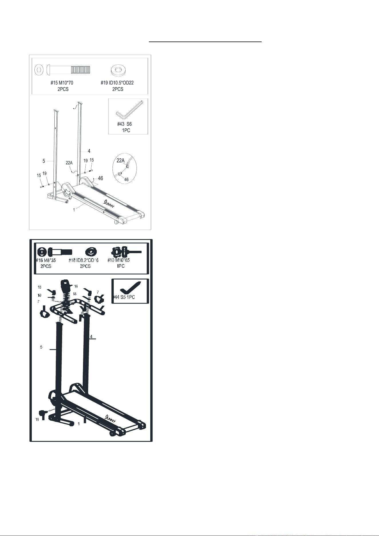
STEP 4:
Attach the Handlebar (No. 6) to the Right & Left
Upright Supports (No. 4 & No. 5) using 2 Arc
Washers (No. 18) and 2 Bolts (No. 16). Tighten and
secure with Allen Wrench (No. 44). Next, connect
the Lower Sensor Wire (No. 22A) to the Upper
Sensor Wire (No. 22B).
Open the battery cover of the Computer (No. 8),
insert 2 AAA batteries, and close the cover. Connect
the Upper Sensor Wire (No. 22B) to the link wire of
Computer (No. 8) Remove 4 Screws (No. 52) from
the Meter (No. 8) by using Allen Wrench (No. 44).
Attach the Meter (No. 8) on the Handlebar (No. 6)
using 4 Screws (No. 52), tighten with Allen Wrench
(No. 44).
Attach 2 Decorative Covers (No. 7) onto the
Handlebar (No. 6).
Screw the Lock Knob (No. 10) into the holes of the
Left Upright Support (No. 5) and Main Frame (No.
1).
Note: Make sure to tighten 2 Bolts (No. 16) to Main
Frame (No. 1) in Step 4 and make sure all other bolts
are tightened.
The assembly is complete!
STEP 3:
Attach the Main Frame (No. 1) to the Right & Left
Upright Supports (No. 4 & No. 5) using 2 Flat
Washers (No. 19) and 2 Bolts (No. 15).
Note: Do not tighten the 2 Bolts (No. 15) to the
Main Frame (No. 1) yet.
Connect the Lower Sensor Wire (No. 22A) to
Sensor Wire (No. 46).
6
LUBRICATING THE TREADMILL
IMPORTANT NOTE:
You will need to lubricate your treadmill before the first use!
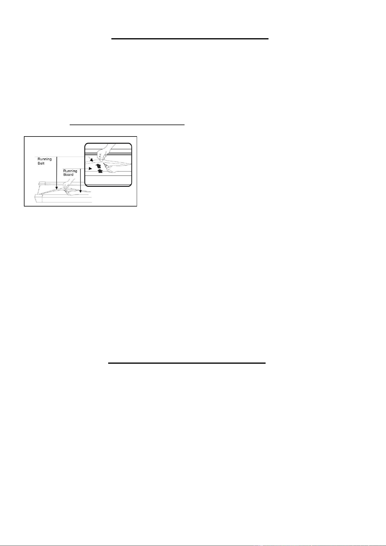
RUNNING BELT & TREADMILL LUBRICANT:
Lubricating the Running Board (No. 26) and Running Belt (No. 2) is essential as the friction
affects the life span and operations of the treadmill. Inspect the Running Board (No. 26) and
Running Belt (No. 2) regularly. If you find any wear on the Running Board (No. 26), please
contact us at [email protected].
The following time table is recommended:
Light user (less than 3 hours/ week) once a year
Medium user (3-5 hours/ week) every six months
Heavy user (more than 5 hours/ week) every three months
1. Raise the Running Belt (No. 2) up on one side, apply lubricant to the Running Board (No.
26). Using a rag, thoroughly wipe the lubricant over the Running Board (No. 26) and repeat
the same process for the other side.
2. The moving parts should turn freely and quietly. Abnormal moving parts will affect the safety
of the treadmill. Checking and tightening bolts in each part of the treadmill regularly is very
important.
3. To better maintain the treadmill and prolong its life, it is suggested that maintenance be done
on a regular and consistent basis.
4. DO NOT LOOSEN OR MAKE ANY ADJUSTMENTS TO THE RUNNING BELT WHILE
APPLYING LUBRICANT. A loose Running Belt (No. 2) will result in the runner sliding off
when in use, while too tight of a Running Belt (No. 2) will create more friction between the
roller and Running Belt (No. 2). The most suitable tightness for the Running Belt (No. 2) is
pulled out 50-75mm from the Running Board (No. 26).
MAINTENANCE INSTRUCTIONS
General cleaning will help to prolong the life and improve performance of your treadmill. Keep
the unit clean and maintained by dusting the components on a regular basis. Cleaning the two
exposed sides of the Running Belt (No. 2) will prevent dust from accumulating underneath.
Keep your running shoes clean so that dirt from the shoes does not wear the Running Board
(No. 26) and Running Belt (No. 2). Clean the surface of the Running Belt (No. 2) using a clean
damp cloth.
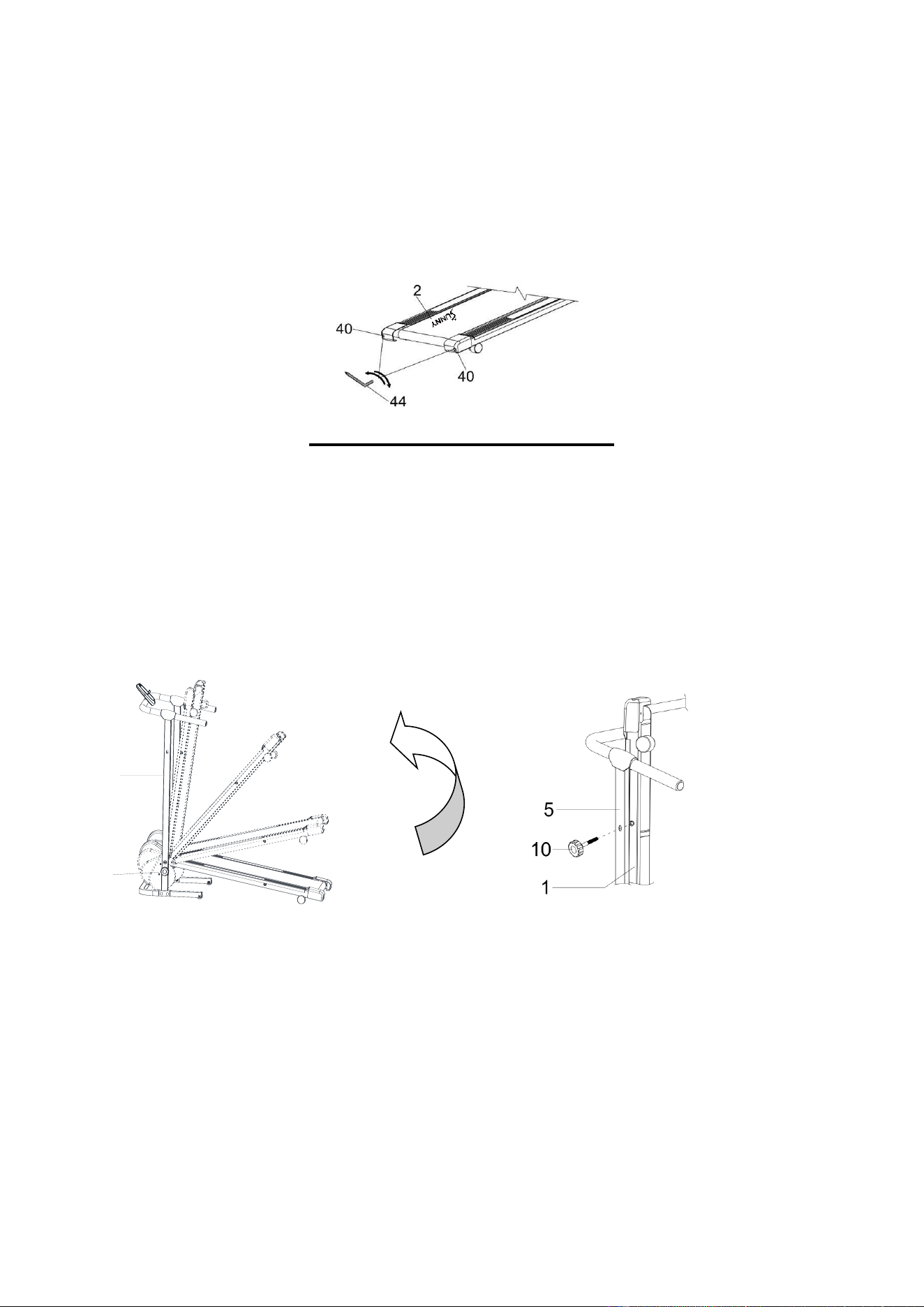
ADJUSTING THE RUNNING BELT:
1. If the Running Belt (No. 2) moves to the right, turn the Adjustable Bolt (No. 40) on the right
side ¼ turn clockwise, then turn the Adjustable Bolt (No. 40) on the left side ¼ turn
counter-clockwise. If the Running Belt (No. 2) does not move, repeat this step until it
centers.
2. If the Running Belt (No. 2) moves to the left, turn the Adjustable Bolt (No. 40) on the left
side ¼ of a circle counter-clockwise, then turn the Adjustable Bolt (No. 40) on the right
side ¼ turn clockwise. If the Running Belt (No. 2) does not move, repeat this step until it
centers.
7
3. Over time the Running Belt (No. 2) will loosen. To tighten the Running Belt (No. 2), turn
both the Adjustable Bolts (No. 40) on the left and right sides one full turn clockwise. Check
the tension of the Running Belt (No. 2). Continue this process until Running Belt (No. 2) is
at the correct tension. Make sure to adjust both sides equally to ensure even alignment.
During exercise, if the Running Belt (No. 2) feels loose, you can tighten the Running Belt (No. 2)
a little by rotating both Adjustable Bolts (No. 40) at the same time ¼ turn clockwise. If the
Running Belt (No. 2) feels too tight, you can loosen the Running Belt (No. 2) by rotating both
Adjustable Bolts (No. 40) at the same time ¼ turn counter-clockwise. You can repeat this
adjustment to obtain your desired belt tightness.
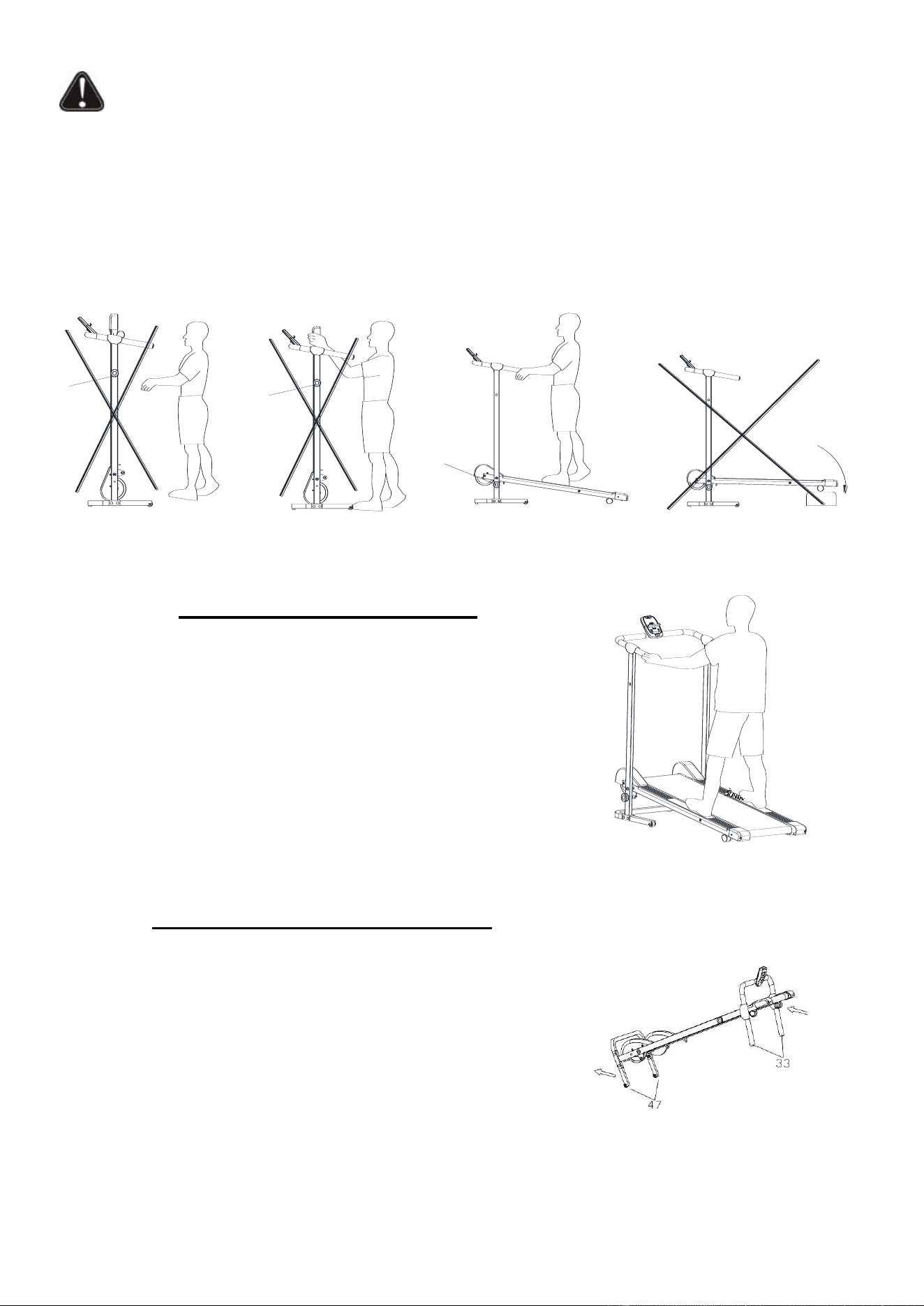
FOLDING INSTRUCTIONS
Folding: To fold the treadmill, turn the Lock Knob (No. 10) counter-clockwise and remove it
from the lower hole of the Left Upright Support (No. 5). Raise the rear end of the Main Frame
(No. 1) all the way up to a vertical position, then insert the Lock Knob (No. 10) to the upper hole
of Left Upright Support (No. 5) and turn clockwise to tighten it. (See figure below).
Unfolding: To unfold the treadmill, turn the Lock Knob (No. 10) counter-clockwise and remove
it from the upper hole of the Left Upright Support (No. 5). Hold the rear end of the Main Frame
(No. 1) and lower it all the way down to the ground, insert the Lock Knob (No. 10) into the lower
hole of the Left Upright Support (No. 5) and turn clockwise to tighten.
10
5
8
WARNING!
1. When folding or unfolding the treadmill, always ensure that the Lock Knob (No. 10) is inserted
correctly and properly tightened.
2. For their safety, children should be kept away from the equipment, even when folded.
3. A folded treadmill should not be operated.
4. Do not fold the treadmill until the running belt stops completely.
5. Before folding up or down, do not stand on the running board.
1.
2.
EMERGENCY DISMOUNT
Be aware of your body’s signals. Incorrect or excessive exercise
can damage your health. If you feel dizziness, nausea, chest
pain, back pain, or other health symptoms, stop the workout
immediately and consult your physician before continuing.
Stand feet on the staging platforms (as shown in the right figure)
and hold the handlebars tightly.
HOW TO MOVE THE TREADMILL
Before attempting to move the treadmill, please make sure that
it has been properly folded.
Moving: Hold the Handlebar Foams (No. 33) with your hands,
slowly tilt the treadmill back towards your body. Once the
Transportation Wheels (No. 47) touch the ground you can
safely move the treadmill to your desired location (see right
figure).
10
10
10

9
EXERCISE COMPUTER
BLUETOOTH :
1. The Bluetooth icon will flash when the computer is on or wakes from sleep mode. If no
Bluetooth connection is established within 1 minute, the Bluetooth icon will turn off.
2. The Bluetooth icon will stay on when it is connected.
3. Bluetooth will get disconnected by pressing MODE button for 6 seconds or stop exercising for
4 minutes.
WIRELESS HEART RATE :
1. The wireless heart rate icon will flash when the meter is on. If the heart rate monitor is not
connected within 1 minute, the wireless heart rate icon will turn off.
2. After exercise resumes, the wireless heart rate icon will flash. If the heart rate monitor is not
connected within 1 minute, the wireless heart rate icon will turn off.
3. When the meter wakes from sleep mode, the wireless heart rate icon will flash. If the heart
rate monitor is not connected within 1 minute, the wireless heart rate icon will turn off.
4. The wireless heart rate icon will flash when the MODE key is pressed. If the heart rate
monitor is not connected within 1 minute, the wireless heart rate icon will turn off.
5. The wireless heart rate icon will stay on when the heart rate monitor is connected.
NOTE: The heart rate monitor is not included. Wireless heart rate function works with SunnyFit
Heart Rate Monitor HR200. HR200 can only connect to the computer when the wireless heart
rate icon is flashing.
FUNCTION BUTTON
1. MODE: Press to switch display or automatically display through each function value in
sequence every 6 seconds.
2. Hold the MODE key for 2 seconds to reset all values except ODO when the Bluetooth is not
connected.
3. Press and hold the MODE key for 6 seconds to disconnect from both the SunnyFit APP and
the heart rate monitor; then, the meter will enter sleep mode.
OPERATION PROCEDURES:
Auto On/Off:
1. Computer with aumatically activated when in use for 10 seconds or MODE button is pressed.
2. Computer will display STOP for inactivity within 10 seconds.
3. Computer with shut off and without activity for 4 minutes and Bluetooh will get disconnected.
Reset: All functions will reset to zero if batteries are out of power or removed.
10
SPECIFICATIONS:
TIME---------------------------------------------------- 00:00-99:59 MIN: SEC
SPEED------------------------------------------------- 0.0-999.9 M (Miles) /H
CALORIE---------------------------------------------- 0.0-999.9 KCAL
ODOMETER------------------------------------------ 0.00-9999.9 M (Miles)
DISTANCE-------------------------------------------- 0.0-999.9 M (Miles)
PULSE------------------------------------------------- 30-240 (Beats)/Min
FUNCTIONS
SCAN: After power on or press the mode button, automatically scan through each function value in
sequence every 6 seconds. SCAN: TIME→SPD→CAL→ODO→DIST→PULSE→SCAN
TIME: Accumulates total training time
SPD: Display current training speed
CAL: Accumulates calories consumption during training
ODO: Accumulates training distance
DIST: Displays the current movement distance of the user
PULSE (Needs to pair with the Bluetooth device): When the heart rate is detected, the real-time
value of the heart rate is displayed, the heart rate icon flashes. When there is no heart rate, P is
displayed. The heart rate icon change from flashing to off.
Note: This data is a rough guide for comparison of different exercise sessions which can not
be used in medical treatment.
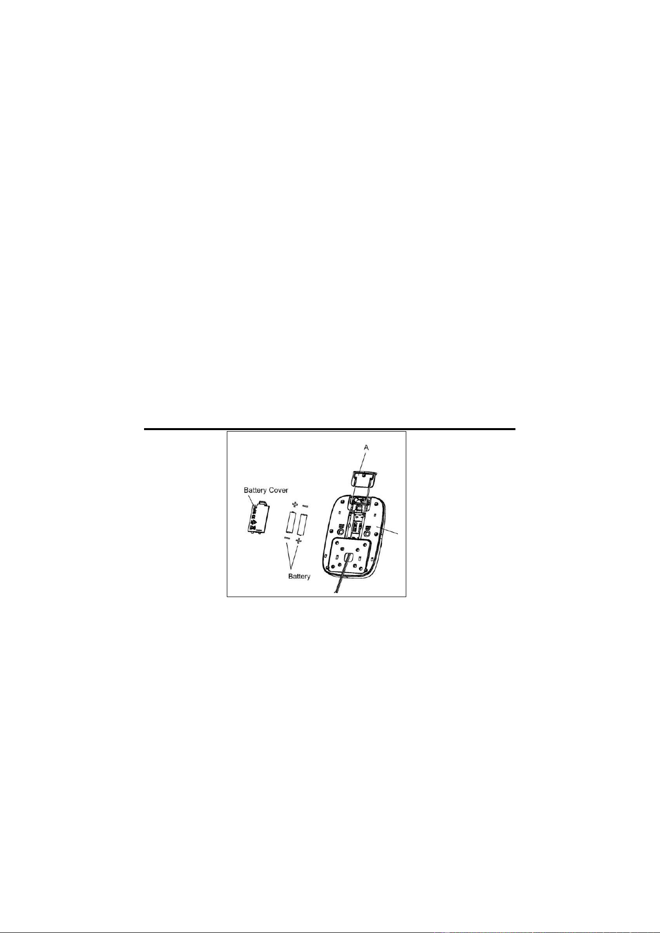
BATTERY INSTALLATION & REPLACEMENT
BATTERY INSTALLATION:
1. Take out 2 AAA batteries from computer box.
2. Pull out the SUNNY insert (No. A), press the buckle of battery cover on the back of the
Computer (No. 8), then remove battery cover.
3. Install 2 AAA batteries into the battery case on the back of the Computer (No. 8). Pay
attention to the battery + and – poles before installing.
4. Press the buckle of battery cover, then put the battery cover back to the back of the
Computer (No. 8).
The installation is complete!
BATTERY REPLACEMENT:
1. Press the buckle of battery cover on the back of the Computer (No. 8), then remove battery
cover.
2. Remove the 2 old AAA batteries in the battery case and install 2 new AAA batteries into the
battery case on the back of the Computer (No.8). Pay attention to the battery + and – poles

11
before installing.
3. Press the buckle of battery cover, then put the battery cover back to the back of the
Computer (No. 8).
The replacement is complete!
NOTE: Always change both batteries at the same time. Do not mix battery types and do not mix
old and new batteries. Dispose batteries according to your state and regional guidelines.
TROUBLESHOOTING
PROBLEM
POSSIBLE CAUSE
SUGGESTED ACTION
Base is unstable.
There is an object under the
main frame of the treadmill, or
the ground isn’t level.
Remove the object.
Move the treadmill to level
ground.
The lock knob is loose.
Tighten the lock knob.
Noise from moving
parts.
Hardware: nuts, bolts, or screws
are loose.
Inspect hardware and tighten.
Running belt and running board
are not lubricated.
Lubricate running belt and
running board (see Pg. 11).
Running belt is not
centered.
Running belt tension is not
accurate on the left or right
sides of the running board.
Adjust the adjustable bolts, refer
to Maintenance Instructions (see
Pg. 11).
The computer
screen does not
display clearly.
The batteries are low.
Replace with new batteries.
The computer does
not work at all.
One of the following sensor
wires is not connected correctly:
the Sensor Wire (No. 46),
Lower Sensor Wire (No. 22A),
or Upper Sensor Wire (No.
22B).
Check the connections of the
sensor wires, make sure they are
attached correctly.
The batteries are unresponsive.
Replace with new batteries.

12
APP CONNECTION:
CONNECT SMART EQUIPMENT TO SUNNYFIT APP:
1. Scan to download SunnyFit from the app store.
2. Ensure that the Bluetooth function is turned on from your mobile device.
3. If this is your first time using the SunnyFit app, follow the in-app instructions to register for
your free SunnyFit account and log in.
4. Begin any workout activity that matches your smart equipment, then follow the onscreen
prompts to search for and connect to your smart equipment.
5. When connected, your stats and records will be displayed at the end of your course/session,
and recorded in your account profile!
TROUBLESHOOTING:
•
If you are having trouble connecting your smart equipment, visit www.sunnyfit.com/guide or
scan the QR code below:
•
If you require additional support, please contact [email protected].

13
PARTS LIST
No.
Description
Spec.
Qty.
No.
Description
Spec.
Qty.
1
Main Frame
1
26
Running Board
1
2
Running Belt
1
27
Front Roller
1
3L
Left Flywheel Cover
1
28
Rear Roller
1
3R
Right Flywheel Cover
1
29
Side Rail
2
4
Right Upright Support
1
30
Anti-slip Cloth
2
5
Left Upright Support
1
31L
Left Side Rail Block
1
6
Handlebar
1
31
R
Right Side Rail Block
1
7
Decorative Cover
2
32
Foot Cover
2
8
Computer
TZ-1130
1
33
Handlebar Foam
2
9
Washer
Φ6*Φ13*1
4
34
End Cap
2
10
Lock Knob
M10*65
1
35
Bolt
M8*40
2
11
Foot Pad
2
36
Rear Axle
1
12
Flat Washer
ID8.2*OD16
4
37
Nylon Nut
M8
6
13
Phillips Head Screw
ST4.2*13
9
38
Inductor Fixing Seat
1
14
Phillips Head Screw
M5*10
4
39
Plastic Washer
D12.5*10
2
15
Bolt
M10*70
2
40
Adjustable Bolt
M6*75
2
16
Bolt
M8*35
2
41
Plastic Washer
D12.5*14
2
17
Carriage Bolt
M8*50
4
42
Spanner
S13-15
1
18
Arc Washer
ID8.2*OD16
2
43
Allen Wrench
S6
1
19
Flat Washer
ID10.5*OD2
2
2
44
Allen Wrench
S5
1
20
Bolt
M6*15
1
45
Cross Screw
ST5.5*25
8
21
Plug
4
46
Sensor Wire
1
22A
Lower Sensor Wire
1
47
Transportation Wheel
2
22B
Upper Sensor Wire
1
48
Plate for Rear Roller
2
23
Base Frame
1
49
Handlebar Foam
2
24L
Rear End Cover L
1
50
Nut
M10
1
24R
Rear End Cover R
1
51
Washer
D12.5
4
25
Front Axle
1
52
Screw
M6*12
4
13
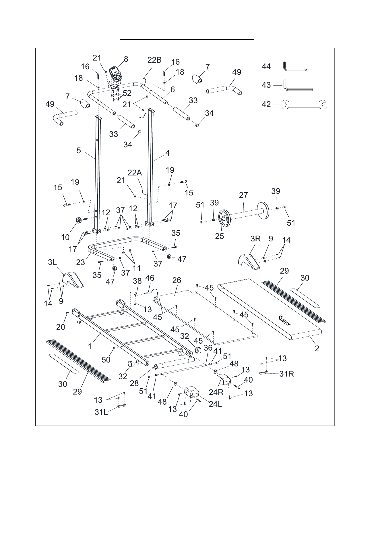
EXPLODED DIAGRAM
Version: 1.0