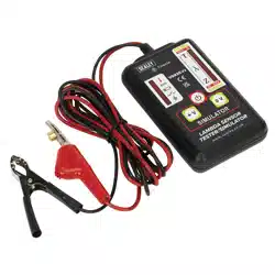
LAMBDA SENSOR TESTER/SIMULATOR
MODEL NO:VS925.V2
Thank you for purchasing a Sealey product. Manufactured to a high standard, this product will, if used according to these instructions,
and properly maintained, give you years of trouble free performance.
IMPORTANT: PLEASE READ THESE INSTRUCTIONS CAREFULLY. NOTE THE SAFE OPERATIONAL REQUIREMENTS, WARNINGS & CAUTIONS. USE
THE PRODUCT CORRECTLY AND WITH CARE FOR THE PURPOSE FOR WHICH IT IS INTENDED. FAILURE TO DO SO MAY CAUSE DAMAGE AND/OR
PERSONAL INJURY AND WILL INVALIDATE THE WARRANTY. KEEP THESE INSTRUCTIONS SAFE FOR FUTURE USE.
Refer to
instruction
manual
Original Language Version
© Jack Sealey Limited
1. SAFETY
WARNING! Ensure Health and Safety, local authority and general workshop practice regulations are adhered to when using tools.
8 DO NOT use tester if damaged.
9 Maintain tester in good and clean condition for best and safest performance.
9 Ensure that a vehicle which has been jacked up is adequately supported with axle stands.
9 Wear approved eye protection. A full range of personal safety equipment is available from your Sealey stockist.
9 Wear suitable clothing to avoid snagging. Do not wear jewellery and tie back long hair.
9 Account for all tools and parts being used and do not leave any on or near the engine.
9 Ensure the handbrake is applied on the vehicle under test and if the vehicle has automatic transmission, put it in the park position.
9 Always ensure there is adequate ventilation when working with engine running. Emissions of carbon monoxide (if inhaled) can cause
serious damage to health.
WARNING! Lambda/O2 sensors are located within the exhaust system, when working on them be well aware of extremes of heat.
2. INTRODUCTION
Tests Zirconia and Titania lambda sensors and ECU. Suitable for 1, 2, 3 and 4 wire sensors, heated and unheated. LED display
shows crossover signal from sensor. Simulates rich or lean mixture signals to check ECU response. Insulation-piercing clip for quick
andeasyconnectionplusdisplaytoconrmwireidentity.Featuresalowbatteryindicatorandpoweredby9Vbattery(supplied).
3. SPECIFICATION
Model No: .......................................................VS925.V2
Battery .......................................................................9V
Operating Temperature .............................10°Cto50°C
Storage Temperature ................................20°C to 60°C
Size (L x W x D) ......................................147x81x29mm
Wear eye
protection
VS926.V2Issue:2(H,F)31/05/23
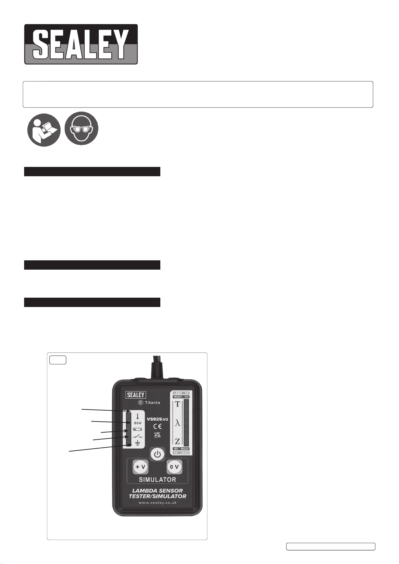
INDICATOR PANEL
The tester can indicate which wire on the Lambda sensor
the unit is connected. This tells the operator which is the
signal wire for measuring the Lambda output and also
identiesthepresenceoftheheatersupplyvoltage(where
applicable) and the sensor ground condition.
Heater voltage
supply
fig.1
ECU 5V Supply
(Titania sensor)
Low battery indicator
Open curcuit Led
Earth

© Jack Sealey Limited
Original Language Version
VS926.V2Issue:2(H,F)31/05/23
4. OPERATION
NOTE: DEFAULT SETTING IS ZIRCONIA SENSOR MODE. TITANIA SENSOR MUST BE MANUALLY SELECTED (see below) &
THE RICH & LEAN VALUES ARE REVERSED.
4.1. SELECTING TITANIA
4.2. To select Titania mode, press the “+V” button while holding the “+ V” button. When the tester turns on the Titania LED will illuminate.
(fig.1)
NOTE: Theenginemustbeatnormaloperatingtemperatureandrunningat1500-2000RPMtotesttheO
2
sensor.
The tester is fitted with a wire-piercing clip allowing it to pierce the sensor wires without damage, (the insulation reforms to its original
state after removal).
4.3. Switch on the tester by pressing the “ ” button. Connect the black ground clip to a good chassis ground, or the negative terminal of the
vehicle’s battery. Connect the wire-piercing clip to one of the sensor wires. The tester can test 1, 2, 3, and 4 sensor wires.
4.4. When testing 2, 3 or 4 wire sensors, the indicator panel (fig.1) will identify which wire you are connected to.
4.5. If the top LED illuminates it indicates the clip is connected to the heater supply voltage.
4.6. IfthesecondLEDilluminatesthisindicatesaconnectiontotheECU5Vsupply,(applicableinthecaseofTitaniasensor,wherefitted).
4.7. The open circuit LED will illuminate when the tester is switched on but not connected to any sensor wires, if a bad connection is made
to any if the sensor wires this LED will stay lit. Once a good connection is made the LED will go out, and one of the other LED’s will
illuminate to indicate which sensor wire is connected. When connection to the signal wire is made the lights on the vertical display will
goout,thenthedisplayLEDarrayIntheLambdawindowwillactivate.(g.1).
4.8. A healthy sensor will show movement across the light path and will illuminate the LEDs in the Lambda window. Once the Lambda
windowisilluminatedignoreanyickeringoftheLEDsintheindicatorpanel.
4.9. Ifconnectedindefault(ZIRCONIA)mode,andonlythetop2lightsontheLambdawindowareickering,thiscouldindicateaTitania
sensor. Leaving the unit connected tothesignalwire,switchtheunitoandfollowinstructionsforselectingTitaniasensor.Ifthe
lights then show movement across the Lambda window, this would then indicate a Titania sensor on the vehicle.
TITANIA SENSOR (RICH & LEAN SIGNALS ARE REVERSED).
4.10. When a Lambda sensor is working correctly in good conditions this will be shown in the Lambda Window with the LED array illuminating
continuously from lean to rich then back again (see fig.1). This pattern is repeated constantly. If the sensor is not working correctly or
there is a fault with the ECU this will not occur and the LED array will remain in the rich or lean sector of the display window, depending
on the type of fault.
4.11. To identify the source of the fault, use the simulation feature of the tester to introduce a rich or lean signal and observe whether this
producesachangeintheLEDactivityontheLambdawindow.Press+V(Titania, press 0V) on the tester it will transmit a RICH
signal to the ECU.
4.11.1. If the circuit is functioning correctly the mixture will be weakened and the result should be apparent by a decrease in the engine
speed occurring. Ideally, a four-gas analyser should be used to verify that the mixture strength varies in response to the false signals
introduced.
4.11.2. Ifthereisnoreactionitwouldsuggestawiring/connectionproblemorfaultyECU.Faultyfuelling,faultyignitionorfaultymanagement
sensors (located on the engine) could also produce the same effect.
4.11.3. If there is a response to the simulated signal the Lambda sensor should be checked, cleaned and tested, and replace or substitute if
necessary.
4.12. In some car management systems, putting in a simulated signal may appear as a fault code in the ECU memory when checked with a
code reader.
4.13. Some management systems have a “limp home device” this is activated when the Lambda sensor fails. The ECU will input a firm value
signalofapprox.500mVtothesensortoallowthevehicletobedrivenatlowspeeds.
5. MAINTENANCE
5.1. The Lambda tester is a sensitive electronic instrument and should be treated as such. Avoid high temperatures, mechanical shock
and damp environments. Check cables for damage and/or loose connections together with battery replacement is the only required
maintenance.
5.2. BATTERY REPLACEMENT
5.3. When the battery voltage is low the LED in the indicator panel will illuminate.
4.2.1 Ensure the two clips are removed from the sensor wires and the ground point.
4.2.2 Remove the battery cover on the rear of the tester by sliding in the direction of the arrow.
4.2.3 Unplug the battery connector and replace with a battery of the same type and rating, replace the battery cover ensuring it snaps into
place.
Sealey Group, Kempson Way, Suffolk Business Park, Bury St Edmunds, Suffolk. IP32 7AR
01284 757500 sales@sealey.co.uk www.sealey.co.uk
Note: It is our policy to continually improve products and as such we reserve the right to alter data, specifications and component parts without prior
notice. Pleasenotethatotherversionsofthisproductareavailable.Ifyourequiredocumentationforalternativeversions,pleaseemailorcall
ourtechnicalteamontechnical@sealey.co.ukor01284757505.
Important: No Liability is accepted for incorrect use of this product.
Warranty: Guarantee is 12 months from purchase date, proof of which is required for any claim.
ENVIRONMENT PROTECTION
Recycle unwanted materials instead of disposing of them as waste. All tools, accessories and packaging should be sorted,
taken to a recycling centre and disposed of in a manner which is compatible with the environment. When the product
becomes completely unserviceable and requires disposal, drain any fluids (if applicable) into approved containers and
dispose of the product and fluids according to local regulations.
REGISTER YOUR
PURCHASE HERE
WEEE REGULATIONS
Dispose of this product at the end of its working life in compliance with the EU Directive on Waste Electrical and Electronic Equipment
(WEEE). When the product is no longer required, it must be disposed of in an environmentally protective way. Contact your local solid
waste authority for recycling information.
BATTERY INFORMATION
UndertheWasteBatteriesandAccumulatorsRegulations2009,JackSealeyLtdwouldliketoinformtheuserthatthisproductcontains
one or more batteries.
VS926.V2Issue:2(H,F)31/05/23
Original Language Version
© Jack Sealey Limited
