INSTRUCTIONS FOR:
BUSH REMOVAL TOOL (PEUGEOT/
CITROEN)
MODEL NO: VSE4785
1. SAFETY
3. SPECIFICATION
4. CONTENTS
2. INTRODUCTION
VSE4785 Issue: 1 - 16/11/15
Original Language Version
© Jack Sealey Limited
IMPORTANT: PLEASE READ THESE INSTRUCTIONS CAREFULLY. NOTE THE SAFE OPERATIONAL REQUIREMENTS, WARNINGS & CAUTIONS. USE THE
PRODUCT CORRECTLY AND WITH CARE FOR THE PURPOSE FOR WHICH IT IS INTENDED. FAILURE TO DO SO MAY CAUSE DAMAGE AND/OR
PERSONAL INJURY AND WILL INVALIDATE THE WARRANTY. KEEP THESE INSTRUCTIONS SAFE FOR FUTURE USE.
Thank you for purchasing a Sealey product. Manufactured to a high standard, this product will, if used according to these
instructions, and properly maintained, give you years of trouble free performance.
Model No: ..................VSE4785
Applications-: ........ Citroen C5 (04-15)
. . . . . . . . . . . . . . . . . . . Citroen C6 (05-15)
. . . . . . . . . . . . . . . . . .Peugeot 407 (04-15)
. . . . . . . . . . . . . . . . . .Peugeot 508 (10-15)
WARNING! Ensure Health and Safety, local authority and general workshop practice regulations are adhered to when using tools.
DO NOT use tools if damaged.
Maintain tools in good and clean condition for best and safest performance.
Ensure that a vehicle which has been jacked up is adequately supported with axle stands and that the wheels are chocked, refer to
the vehicle manufacturer’s service instructions, or a proprietary manual.
Wear approved eye protection. A full range of personal safety equipment is available from your Sealey dealer.
Wear suitable clothing and tie back long hair to avoid snagging. DO NOT wear jewellery.
DO NOT use air tools to operate the force screw.
IMPORTANT: The force screw must be kept well lubricated. A copper based grease lubricant is recommended.
IMPORTANT: This manual is provided as a guide only, refer to the vehicle manufacturer’s service instructions, or a proprietary
manual, to establish the current procedure and data. Pictures shown are with the housing removed from the vehicle.
WARNING! Failure to heed safety and warning instructions may result in damage and/or personal injury and will invalidate
the warranty.
WARNING! The warnings, cautions and instructions referred to in this manual cannot cover all possible conditions and
situations that may occur. It must be understood that common sense and caution are factors which cannot be built into this
product, but must be applied by the operator.
Refer to the instruction
manual.
Wear eye protection
Wear protective gloves
ALWAYS KEEP FORCE SCREW
WELL LUBRICATED.
DO NOT USE AIR TOOLS
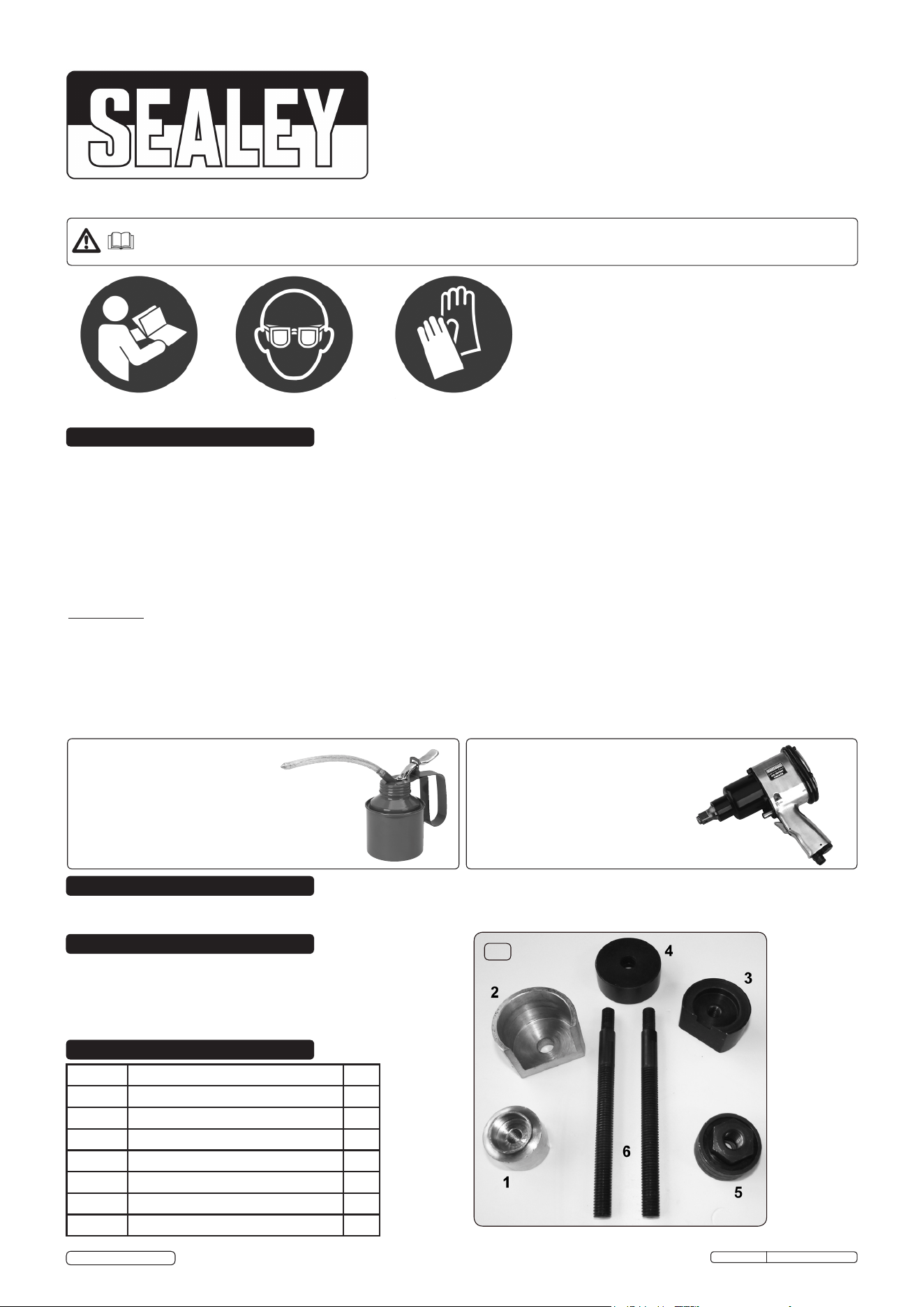
g.1
Item No Description Qty
1 Extract Mandrel (Zinc Plated) 1
2 Thrust Cup (Zinc Plated) 1
3 Insertion Mandrel (Blackened) 1
4 Thrust Ring (Blackened) 1
5 Thrust Race Assembly 1
6 Force Screw (M12 X 2) 2
7 Carry Case (not shown) 1
Suitable for the removal/installation of the front lower suspension pivot arm bush. It can be used in situ without removing the aluminium alloy
hub carrier from the vehicle.
X
Environmental Protection
Recycle unwanted materials instead of disposing of them as waste. All tools, accessories and packaging should be
sorted, taken to a recycling centre and disposed of in a manner which is compatible with the environment.
When the
product becomes completely unserviceable and requires disposal, dispose of the product according to local regulations
Parts support is available for this product. To obtain a parts listing and/or diagram,
please log on to www.sealey.co.uk, email sales@sealey.co.uk or telephone 01284 757500.
5. OPERATION
6. MAINTENANCE
VSE4785 Issue: 1 - 16/11/15
NOTE: It is our policy to continually improve products and as such we reserve the right to alter data, specifications and component parts without prior notice.
IMPORTANT: No liability is accepted for incorrect use of this product.
WARRANTY: Guarantee is 12 months from purchase date, proof of which will be required for any claim.
01284 757500
01284 703534
sales@sealey.co.uk
Sole UK Distributor, Sealey Group,
Kempson Way, Suffolk Business Park,
Bury St. Edmunds, Suffolk,
IP32 7AR
www.sealey.co.uk
Original Language Version
© Jack Sealey Limited
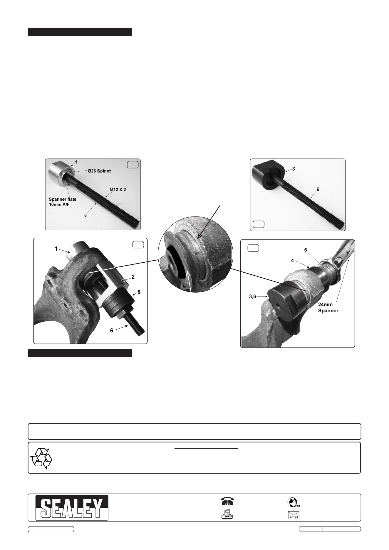
5.1. Oldbushextraction(g.4)
5.1.1. Assembletheforcescrewwiththezincplatedmandrelasing.2.
5.1.2. Pass the force screw through the bush bore, centralising the Ø26 spigot about the bush.
5.1.3. Offer the zinc plated thrust cup over the force screw and register with the bush housing.
5.1.4. Wind the lubricated thrust race assembly down the lubricated force screw to the thrust cup face.
5.1.5. Check alignment and concentricity of the arrangement prior to introducing a 24mm spanner to extract the bush from the housing.
5.1.6. The bush will extract at a rate of 2mm per complete turn of the spanner.
Important! Do not use excessive force which could lead to the tool being damaged.
5.2. Insertionofthenewbush(g.5)
5.2.1. Clean the housing bore and faces thoroughly. DO NOT lubricate the bore.
5.2.2. Assembletheforcescrewwiththeblackenedmandrelasing.3.Themandrelisrecessedtoregisterwiththebushange.
5.2.3. Offerthenewbushontotheforcescrewandregisterthebushangeintotherecess;presenttheitemstothehousingbore.
5.2.4. Slide the blackened thrust ring down the force screw to the housing bore face and wind the thrust race assembly down to the thrust ring.
5.2.5. Check alignment and concentricity of the arrangement prior to introducing a 24mm spanner to insert the bush into the housing.
5.2.6. The bush will insert at a rate of 2mm per complete turn of the spanner. Observe the depth of insertion, stopping immediately the bush
angeisushwiththehousingface.Thiswillalsobeapparentbyanincreaseinresistance.
g.2
g.3
g.4
g.5
Ø45.5 Bush Flange
Housing Face
6.1 Inspect all components for damage. DO NOT use damaged components. Please note that an Impact Socket must NOT be used
with this tool. Stripped threads and bent thrust cups/rings are not accepted warranty claims on this tool.
6.2. After use, clean all components with a lightly oiled cloth and return to the carry case. Store in a dry location away from children.