FRONT SUSPENSION BUSH TOOL - VAG
MODEL NO: VSE4781
Thank you for purchasing a Sealey product. Manufactured to a high standard, this product will, if used according to these instructions,
and properly maintained, give you years of trouble free performance.
IMPORTANT: PLEASE READ THESE INSTRUCTIONS CAREFULLY. NOTE THE SAFE OPERATIONAL REQUIREMENTS, WARNINGS & CAUTIONS. USE
THE PRODUCT CORRECTLY AND WITH CARE FOR THE PURPOSE FOR WHICH IT IS INTENDED. FAILURE TO DO SO MAY CAUSE DAMAGE AND/OR
PERSONAL INJURY AND WILL INVALIDATE THE WARRANTY. KEEP THESE INSTRUCTIONS SAFE FOR FUTURE USE.
1. SAFETY
WARNING! Ensure Health and Safety, local authority and general workshop practice regulations are adhered to when using tools.
8 DO NOT use tools if damaged.
9 Maintain tools in good and clean condition for best and safest performance.
9 Ensure that a vehicle which has been jacked up is adequately supported with axle stands and that the wheels are chocked, refer to the
vehicle manufacturer’s service instructions, or a proprietary manual.
9 Wear approved eye protection. A full range of personal safety equipment is available from your Sealey stockist.
9 Wear suitable clothing to avoid snagging. DO NOT wear jewellery and tie back long hair.
8 DO NOT use air tools to operate the force screw.
IMPORTANT: The force screw must be kept well lubricated.
IMPORTANT: This manual is provided as a guide only, refer to the vehicle manufacturer’s service instructions, or a proprietary manual, to
establish the current procedure and data.
WARNING! Failure to heed safety and warning instructions may result in damage and/or personal injury and will invalidate the
warranty.
WARNING! The warnings, cautions and instructions referred to in this manual cannot cover all possible conditions and
situations that may occur. It must be understood that common sense and caution are factors which cannot be built into this product,
but must be applied by the operator.
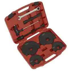
2. INTRODUCTION
Suitable for the removal/installation of the rear mounting bush on the front lower wishbone. Can be used in situ without removing the aluminium
housing. Use with 24mm spanner only. Supplied in storage case.
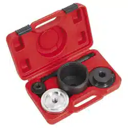
3. CONTENTS
Refer to
instruction
manual
Wear eye
protection
VSE4781 Issue:3 (H,F) 17/06/24
Original Language Version
© Jack Sealey Limited
ALWAYS KEEP FORCE SCREW
WELL LUBRICATED.
DO NOT USE AIR TOOLS
X
Letter Part No. Description
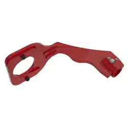
A VSE4781-04 Adaptor silver
B VSE4781-03 Large adaptor
C VSE4781-06 Installation adaptor
D VSE4781-05 Adaptor
E VSE4781-01 Screw nut
F VSE4781-02 Threaded bar
4. APPLICATIONS
Seat: Cordoba III (03on), Skoda: Fabia (00on), VW: Polo IV (02on)
5. OPERATION
NOTE! Pictures taken with the wish-bone removed from it’s housing for clarity. Refer to the vehicle manufacturer’s service
instructions, or a proprietary manual to carry this out.
Thepicturesareofano-sidebushbeingreplaced.
NOTE! This tool will insert the bush to the correct depth, but before installing the new bush, refer to the vehicle
manufacturer’s service instructions, or a proprietary manual, to establish the correct horizontal alignment/positioning of the
bush.
IMPORTANT: This tool is designed to aid removal of the bush. We suggest that the area around the bush is thoroughly cleaned.
The threads of the tool should also be thoroughly lubricated in use.
An Impact Socket must NOT be used with this tool. Stripped threads and bent thrust cups are not accepted warranty claims
on this tool.
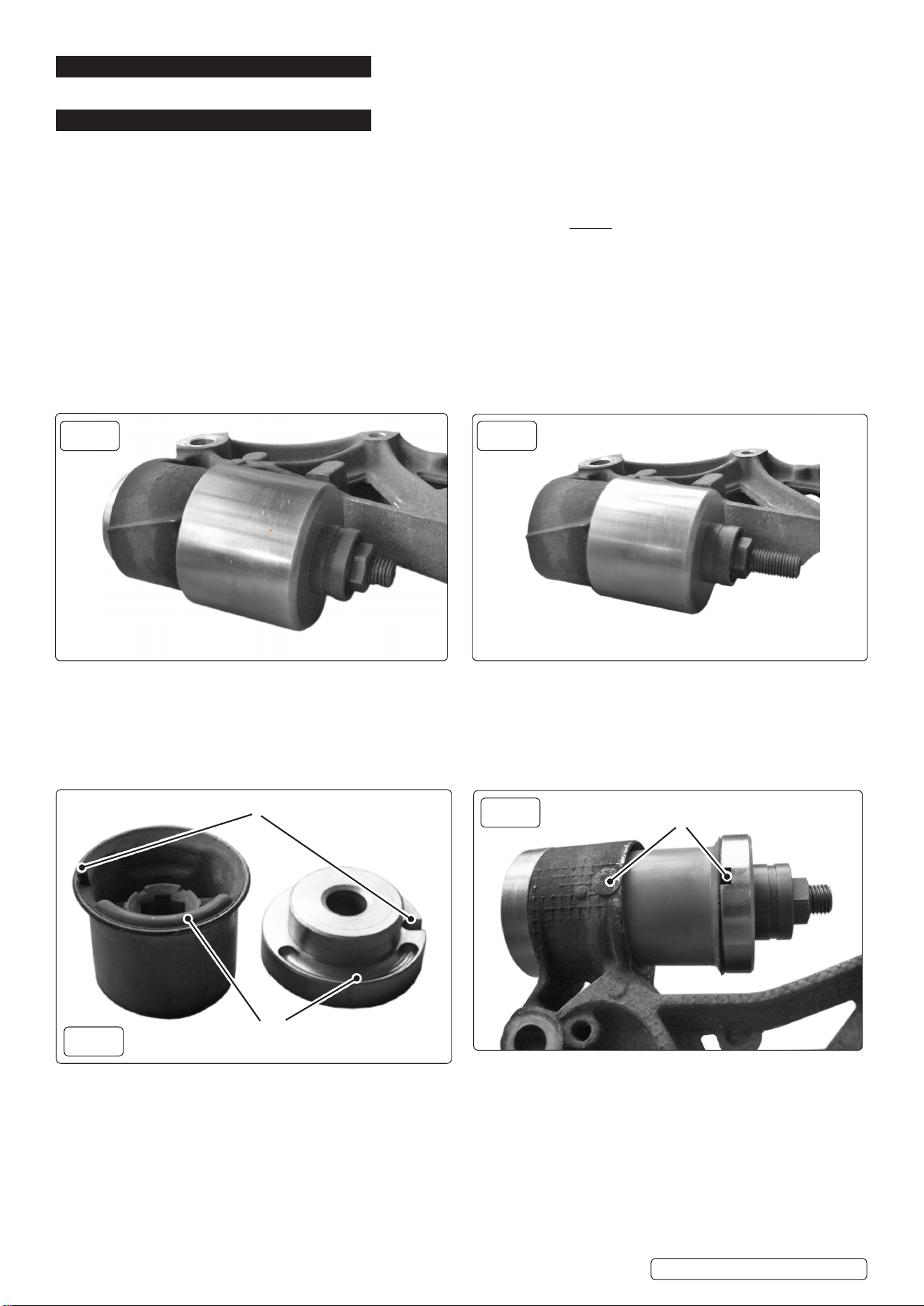
5.1. REMOVING BUSH
5.1.1. Assemble the removal (silver) set as in Fig.1. Thread the Adaptor (A) onto the short threaded end of the bolt (F) with the ridged side
facing forwards.
5.1.2. PasstheboltthroughthebushfromtherearandthenpositionthelargeAdaptor(B)overthebolt,ttingitagainstthehousingwith
thecut-outfacinginwardsandthesmallrecessttedovertherubberlocatoronthebush.
5.1.3. Thread the nut (E) onto the bolt and wind it up to the adaptor. Double check to make sure that everything is aligned.
5.1.4. Using a 24mm spanner, turn the nut clockwise. The extractor will start to extract the bush through the housing (Fig.2).
5.1.5. Keep turning until the bush has been extracted all the way out of the housing. Take care as the bush and assembly will fall away when
the bush is fully removed.
NOTE! If any undue resistance is felt, remove the assembly and check everything is correctly aligned. The bush will only push out in
one direction.
5.2. INSTALLING NEW BUSH
5.2.1. Before installing a new bush, clean the inside of the housing.
5.3.
5.4.
5.5.
5.6.
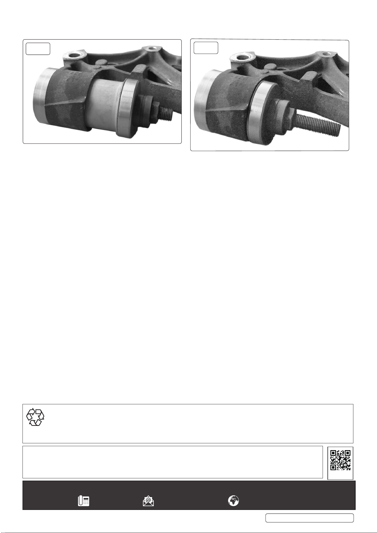
5.6.1. Assemble the installation (gold) set on the housing as in Fig.4 - viewed from below, and Fig.5. Adaptor (D) is threaded onto the short
threaded end of the bolt (F) with the ridged side facing inwards. Pass the bolt through the housing from the rear and then through the
bushandthenpositiontheAdaptor(C)overthebolt,ttingitagainstthebush.
5.6.2. To facilitate correct positioning of the bush, the installation adaptor (C) has 2 recesses that align with the face of the new bush (Fig.3). The
bush should then be aligned in the housing so that the rubber locator on the bush is facing directly downwards (Fig.4). Thread the nut
(E) onto the bolt and wind it up to the adaptor.
5.6.3. Double check to make sure that everything is aligned and that the bush is sitting squarely against the housing.
5.6.4. Using a 24mm spanner, turn the nut clockwise. The bush will start to be pushed into the housing.
NOTE! If any undue resistance is felt, remove the assembly and check that everything is correctly aligned.
5.6.5. Continue to turn the nut to install the bush, when the bush reaches the housing, resistance will be felt and the bush is fully installed
(Fig.6).
Original Language Version
© Jack Sealey Limited
VSE4781 Issue:3 (H,F) 17/06/24
fig.
1
Rear of vehicle
Front of vehicle
fig.
2
Position locator on new bush into recess in installation adaptor.
Ridgeonnewbushtsintogrooveinadaptor
fig.
3
Line up the rubber locator on the new
bush with the bottom of the housing
fig.
4
Sealey Group, Kempson Way, Suffolk Business Park, Bury St Edmunds, Suffolk. IP32 7AR
01284 757500 sales@sealey.co.uk www.sealey.co.uk
ENVIRONMENT PROTECTION
Recycle unwanted materials instead of disposing of them as waste. All tools, accessories and packaging should be sorted, taken to
a recycling centre and disposed of in a manner which is compatible with the environment. When the product becomes completely
unserviceable and requires disposal, drain any fluids (if applicable) into approved containers and dispose of the product and fluids
according to local regulations.
Note: It is our policy to continually improve products and as such we reserve the right to alter data, specifications and component parts
without prior notice.
Important: No Liability is accepted for incorrect use of this product.
Warranty: Guarantee is 12 months from purchase date, proof of which is required for any claim.
5.6.6. Disassemble the tool, clean and lubricate before returning the parts to the storage case.
5.6.7. Re-tthewish-boneasperthe vehicle manufacturer’s service instructions or a proprietary manual.
.
Original Language Version
© Jack Sealey Limited
REGISTER YOUR
PURCHASE HERE
VSE4781 Issue:3 (H,F) 17/06/24
fig.
5
fig.
6