Loading ...
Loading ...
Loading ...
GDS-3000 Series User Manual
190
The calibration for Channel1 starts and ends
automatically, in less than 5 minutes. A
message is displayed when the calibration
procedure has ended.
9. Repeat the above step for Channel 2, 3* and 4*
when prompted.
*4 channel models.
10. When the calibration for all channels has
completed, the display goes back to the default
state.
Probe Compensation
Panel Operation
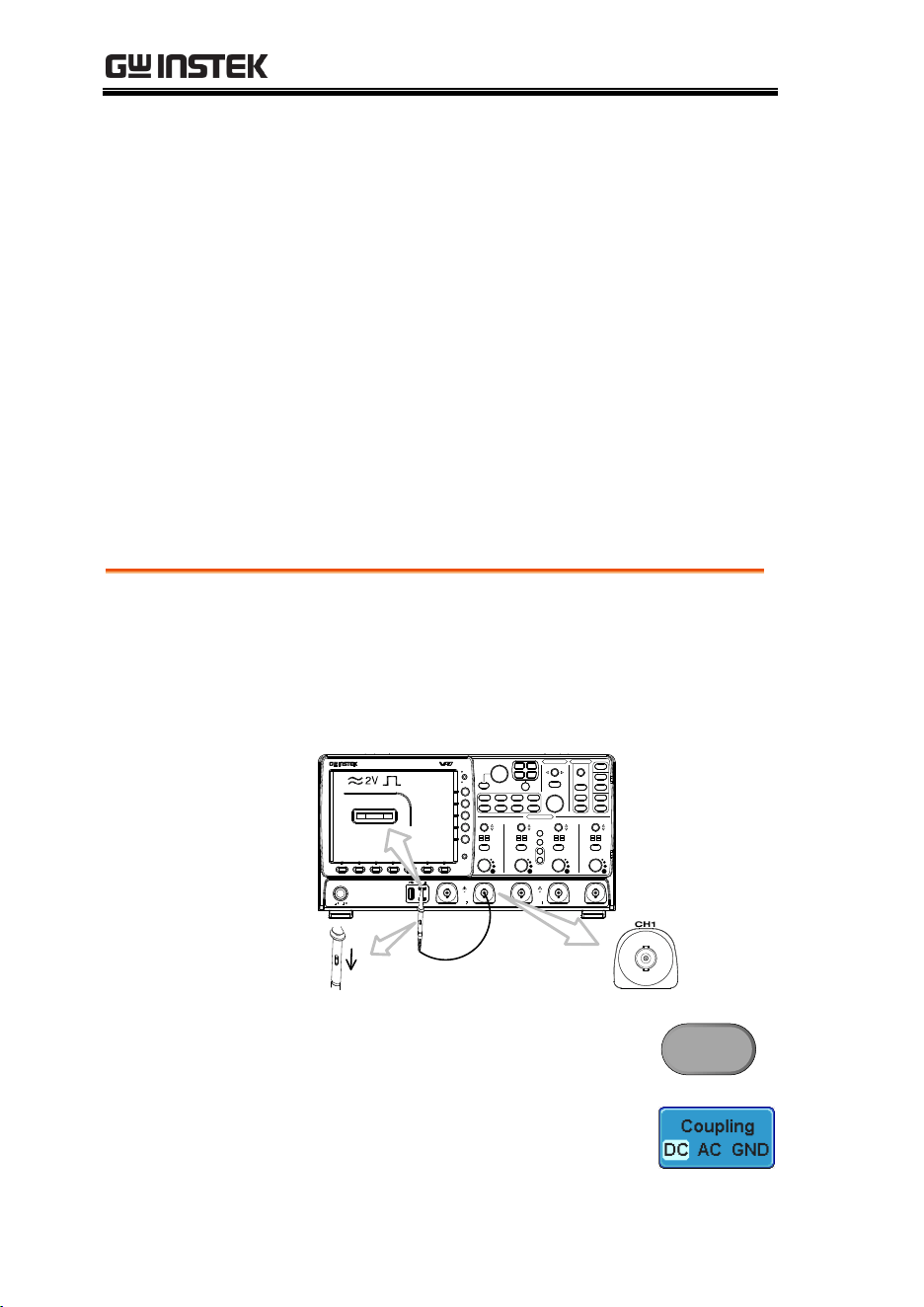
1. Connect the probe between the Channel1 input
and the probe compensation output (2Vp-p,
1kHz square wave) on the front panel. Set the
probe attenuation to x10 (GDP probes are fixed
at x10).
VOLTS/DIV VOLTS/DIV VOLTS/DIV VOLTS/DIV
POSITION
POSITION POSITION
TIME/DIV
POSITION
HORIZONTAL
VARIABLE
W
AC
BW
50
W
75
VERTICAL
LEVEL
POSITION
TRIGGER
W
AC
BW
50
W
75
W
AC
BW
50
W
75
W
AC
BW
50
W
75
CH4CH3CH2CH1EXT TRIG
POWER
2V
Window
Split
Select
Zoom
CH1 CH2 CH3 CH4
R
B1
Measure Cursor
Display Help
Test
Save/Recall Utility
Menu
50 %
Force - Trig
Autoset
Single
Run/Stop
Setup
Auto-Range
Default
Acquire
CAT
M
W
15pF
300Vpk MAX.
1
5 Vrms MAX.
W
50
W
75&
CAT
M
W
15pF
300Vpk MAX.
1
5 Vrms MAX.
W
50
W
75&
M
B2
MATH
REF
BUS
Off
Menu
Print
Save
Digital Storage Oscilloscope
GDS-3354
350 MHz 5 GS/s
Visual Persistence Oscilloscope
x1
x10
X10
X1
2. Press the CH1 key to activate CH1.
CH1
3. Set the Coupling to DC from the
bottom menu.
Loading ...
Loading ...
Loading ...